US10451683B2 - Secondary battery state detection device and secondary battery state detection method - Google Patents
Secondary battery state detection device and secondary battery state detection method Download PDFInfo
- Publication number
- US10451683B2 US10451683B2 US14/449,641 US201414449641A US10451683B2 US 10451683 B2 US10451683 B2 US 10451683B2 US 201414449641 A US201414449641 A US 201414449641A US 10451683 B2 US10451683 B2 US 10451683B2
- Authority
- US
- United States
- Prior art keywords
- secondary battery
- value
- starting
- engine
- diffusion resistance
- Prior art date
- Legal status (The legal status is an assumption and is not a legal conclusion. Google has not performed a legal analysis and makes no representation as to the accuracy of the status listed.)
- Active, expires
Links
Images


Classifications
-
- G—PHYSICS
- G01—MEASURING; TESTING
- G01R—MEASURING ELECTRIC VARIABLES; MEASURING MAGNETIC VARIABLES
- G01R31/00—Arrangements for testing electric properties; Arrangements for locating electric faults; Arrangements for electrical testing characterised by what is being tested not provided for elsewhere
- G01R31/36—Arrangements for testing, measuring or monitoring the electrical condition of accumulators or electric batteries, e.g. capacity or state of charge [SoC]
- G01R31/392—Determining battery ageing or deterioration, e.g. state of health
-
- B—PERFORMING OPERATIONS; TRANSPORTING
- B60—VEHICLES IN GENERAL
- B60R—VEHICLES, VEHICLE FITTINGS, OR VEHICLE PARTS, NOT OTHERWISE PROVIDED FOR
- B60R16/00—Electric or fluid circuits specially adapted for vehicles and not otherwise provided for; Arrangement of elements of electric or fluid circuits specially adapted for vehicles and not otherwise provided for
- B60R16/02—Electric or fluid circuits specially adapted for vehicles and not otherwise provided for; Arrangement of elements of electric or fluid circuits specially adapted for vehicles and not otherwise provided for electric constitutive elements
- B60R16/04—Arrangement of batteries
-
- F—MECHANICAL ENGINEERING; LIGHTING; HEATING; WEAPONS; BLASTING
- F02—COMBUSTION ENGINES; HOT-GAS OR COMBUSTION-PRODUCT ENGINE PLANTS
- F02N—STARTING OF COMBUSTION ENGINES; STARTING AIDS FOR SUCH ENGINES, NOT OTHERWISE PROVIDED FOR
- F02N11/00—Starting of engines by means of electric motors
- F02N11/08—Circuits specially adapted for starting of engines
- F02N11/0862—Circuits specially adapted for starting of engines characterised by the electrical power supply means, e.g. battery
-
- G—PHYSICS
- G01—MEASURING; TESTING
- G01R—MEASURING ELECTRIC VARIABLES; MEASURING MAGNETIC VARIABLES
- G01R19/00—Arrangements for measuring currents or voltages or for indicating presence or sign thereof
- G01R19/165—Indicating that current or voltage is either above or below a predetermined value or within or outside a predetermined range of values
-
- G—PHYSICS
- G01—MEASURING; TESTING
- G01R—MEASURING ELECTRIC VARIABLES; MEASURING MAGNETIC VARIABLES
- G01R27/00—Arrangements for measuring resistance, reactance, impedance, or electric characteristics derived therefrom
- G01R27/02—Measuring real or complex resistance, reactance, impedance, or other two-pole characteristics derived therefrom, e.g. time constant
- G01R27/08—Measuring resistance by measuring both voltage and current
-
- G—PHYSICS
- G01—MEASURING; TESTING
- G01R—MEASURING ELECTRIC VARIABLES; MEASURING MAGNETIC VARIABLES
- G01R31/00—Arrangements for testing electric properties; Arrangements for locating electric faults; Arrangements for electrical testing characterised by what is being tested not provided for elsewhere
- G01R31/36—Arrangements for testing, measuring or monitoring the electrical condition of accumulators or electric batteries, e.g. capacity or state of charge [SoC]
- G01R31/3644—Constructional arrangements
- G01R31/3647—Constructional arrangements for determining the ability of a battery to perform a critical function, e.g. cranking
-
- G—PHYSICS
- G01—MEASURING; TESTING
- G01R—MEASURING ELECTRIC VARIABLES; MEASURING MAGNETIC VARIABLES
- G01R31/00—Arrangements for testing electric properties; Arrangements for locating electric faults; Arrangements for electrical testing characterised by what is being tested not provided for elsewhere
- G01R31/36—Arrangements for testing, measuring or monitoring the electrical condition of accumulators or electric batteries, e.g. capacity or state of charge [SoC]
- G01R31/374—Arrangements for testing, measuring or monitoring the electrical condition of accumulators or electric batteries, e.g. capacity or state of charge [SoC] with means for correcting the measurement for temperature or ageing
-
- G—PHYSICS
- G01—MEASURING; TESTING
- G01R—MEASURING ELECTRIC VARIABLES; MEASURING MAGNETIC VARIABLES
- G01R31/00—Arrangements for testing electric properties; Arrangements for locating electric faults; Arrangements for electrical testing characterised by what is being tested not provided for elsewhere
- G01R31/36—Arrangements for testing, measuring or monitoring the electrical condition of accumulators or electric batteries, e.g. capacity or state of charge [SoC]
- G01R31/385—Arrangements for measuring battery or accumulator variables
- G01R31/387—Determining ampere-hour charge capacity or SoC
-
- G—PHYSICS
- G01—MEASURING; TESTING
- G01R—MEASURING ELECTRIC VARIABLES; MEASURING MAGNETIC VARIABLES
- G01R31/00—Arrangements for testing electric properties; Arrangements for locating electric faults; Arrangements for electrical testing characterised by what is being tested not provided for elsewhere
- G01R31/36—Arrangements for testing, measuring or monitoring the electrical condition of accumulators or electric batteries, e.g. capacity or state of charge [SoC]
- G01R31/389—Measuring internal impedance, internal conductance or related variables
-
- H—ELECTRICITY
- H01—ELECTRIC ELEMENTS
- H01M—PROCESSES OR MEANS, e.g. BATTERIES, FOR THE DIRECT CONVERSION OF CHEMICAL ENERGY INTO ELECTRICAL ENERGY
- H01M10/00—Secondary cells; Manufacture thereof
- H01M10/42—Methods or arrangements for servicing or maintenance of secondary cells or secondary half-cells
- H01M10/48—Accumulators combined with arrangements for measuring, testing or indicating the condition of cells, e.g. the level or density of the electrolyte
-
- H—ELECTRICITY
- H02—GENERATION; CONVERSION OR DISTRIBUTION OF ELECTRIC POWER
- H02J—ELECTRIC POWER NETWORKS; CIRCUIT ARRANGEMENTS OR SYSTEMS FOR SUPPLYING OR DISTRIBUTING ELECTRIC POWER; SYSTEMS FOR STORING ELECTRIC ENERGY
- H02J4/00—Circuit arrangements for mains or distribution networks not specified as AC or DC; Circuit arrangements for mains or distribution networks combining AC and DC sections or sub-networks
- H02J4/20—Networks integrating separated AC and DC power sections
- H02J4/25—Networks integrating separated AC and DC power sections for transfer of electric power between AC and DC networks, e.g. for supplying the DC section within a load from an AC mains system
-
- H02J7/0021—
-
- H—ELECTRICITY
- H02—GENERATION; CONVERSION OR DISTRIBUTION OF ELECTRIC POWER
- H02J—ELECTRIC POWER NETWORKS; CIRCUIT ARRANGEMENTS OR SYSTEMS FOR SUPPLYING OR DISTRIBUTING ELECTRIC POWER; SYSTEMS FOR STORING ELECTRIC ENERGY
- H02J7/00—Circuit arrangements for charging or discharging batteries or for supplying loads from batteries
- H02J7/80—Circuit arrangements for charging or discharging batteries or for supplying loads from batteries including monitoring or indicating arrangements
- H02J7/82—Control of state of charge [SOC]
-
- H—ELECTRICITY
- H02—GENERATION; CONVERSION OR DISTRIBUTION OF ELECTRIC POWER
- H02J—ELECTRIC POWER NETWORKS; CIRCUIT ARRANGEMENTS OR SYSTEMS FOR SUPPLYING OR DISTRIBUTING ELECTRIC POWER; SYSTEMS FOR STORING ELECTRIC ENERGY
- H02J7/00—Circuit arrangements for charging or discharging batteries or for supplying loads from batteries
- H02J7/80—Circuit arrangements for charging or discharging batteries or for supplying loads from batteries including monitoring or indicating arrangements
- H02J7/84—Control of state of health [SOH]
-
- H—ELECTRICITY
- H01—ELECTRIC ELEMENTS
- H01M—PROCESSES OR MEANS, e.g. BATTERIES, FOR THE DIRECT CONVERSION OF CHEMICAL ENERGY INTO ELECTRICAL ENERGY
- H01M2220/00—Batteries for particular applications
- H01M2220/20—Batteries in motive systems, e.g. vehicle, ship, plane
-
- Y—GENERAL TAGGING OF NEW TECHNOLOGICAL DEVELOPMENTS; GENERAL TAGGING OF CROSS-SECTIONAL TECHNOLOGIES SPANNING OVER SEVERAL SECTIONS OF THE IPC; TECHNICAL SUBJECTS COVERED BY FORMER USPC CROSS-REFERENCE ART COLLECTIONS [XRACs] AND DIGESTS
- Y02—TECHNOLOGIES OR APPLICATIONS FOR MITIGATION OR ADAPTATION AGAINST CLIMATE CHANGE
- Y02E—REDUCTION OF GREENHOUSE GAS [GHG] EMISSIONS, RELATED TO ENERGY GENERATION, TRANSMISSION OR DISTRIBUTION
- Y02E60/00—Enabling technologies; Technologies with a potential or indirect contribution to GHG emissions mitigation
- Y02E60/10—Energy storage using batteries
Definitions
- the present invention relates to a secondary battery state detecting device and a secondary battery state detecting method.
- Patent Document 1 an art making a secondary battery perform pulse-discharge in an approximately rectangular shape, sampling a response voltage at that time to expand to a rectangular wave components perpendicular mutually, calculating a pseudo impedance of the secondary battery from an obtained coefficient and current value, and determining deterioration of a secondary battery based on the pseudo impedance, is disclosed.
- Patent Document 1 Japanese Patent Application Laid-open No. 2006-284537
- Patent Document 1 a charge level of the secondary battery is lowered if the pulse-discharge is continued for a long time. Besides, it is necessary to use a resistance element whose capacitance is large to enable the discharge for a long time, and therefore, a size of a device becomes large. Therefore, a time for the pulse-discharge is limited for a short period of time because of these reasons.
- the resistances of the secondary battery there are kinds of resistances as illustrated in FIG. 6 in the resistances of the secondary battery. Namely, there are a conductor resistance, a positive/negative electrode reaction resistance, and a diffusion resistance.
- the conductor resistance and the positive/negative electrode reaction resistance increase in accordance with deterioration of the secondary battery.
- the diffusion resistance is not affected by the deterioration of the secondary battery.
- a most important object to measure an internal resistance of the secondary battery is to detect a degree of deterioration of the secondary battery.
- a discharge time when the internal resistance is measured is set at a range suitable for a deterioration determination illustrated in FIG. 6 , and thereby, a highly accurate detection of degree of deterioration is enabled.
- the discharge time continues for a longer period of time than the case when the internal resistance is measured (the discharge time at the engine start time illustrated in FIG. 6 ), and therefore, the internal resistance increases for an extent of the diffusion resistance as illustrated in FIG. 6 .
- An object of the present invention is to provide a secondary battery state detecting device and a secondary battery state detecting method capable of accurately determining whether or not it is possible to start the engine while accurately detecting the degree of deterioration of the secondary battery.
- the present invention is characterized in that: a measurement unit measuring a value of an internal resistance of a secondary battery at an engine stop time; an estimation unit estimating a value of a diffusion resistance resulting from diffusion of an ion generated at an electrolytic solution of the secondary battery by supplying electric power to a starter motor at a starting time of the engine; and a calculation unit calculating a starting voltage being a voltage required for the starting of the engine from a resistance value obtained by adding the value of the diffusion resistance estimated by the estimation unit to the value of the internal resistance measured by the measurement unit, a starting current flowing when the engine is started, and a voltage before starting of the secondary battery, are included in a secondary battery state detecting device detecting a state of the secondary battery mounted on a vehicle.
- Another invention is characterized in that: the estimation unit estimates the value of the diffusion resistance based on a discharge current, a discharge time at the starting time of the engine, and a temperature of the secondary battery in addition to the above-stated invention.
- Still another invention is characterized in that: the estimation unit estimates the value of the diffusion resistance by setting at least one of the discharge current, the discharge time, and the temperature of the secondary battery as a fixed value, and setting the others as variable values, and an obtained value of the diffusion resistance is corrected based on a parameter which is set as the fixed value in addition to the above-stated invention.
- Still another invention is characterized in that: the estimation unit sets the temperature as the fixed value, the discharge current and the discharge time as the variable values, estimates the value of the diffusion resistance based on the discharge current and the discharge time at a predetermined temperature, and corrects the value of the estimated diffusion resistance based on an actually measured temperature of the secondary battery in addition to the above-stated invention.
- the present invention is characterized in that: a measurement step measuring a value of an internal resistance of a secondary battery at an engine stop time; an estimation step estimating a value of a diffusion resistance resulting from diffusion of an ion generated at an electrolytic solution of the secondary battery by supplying electric power to a starter motor at a starting time of the engine; and a calculation step calculating a starting voltage being a voltage required for the starting of the engine from a resistance value obtained by adding the value of the diffusion resistance estimated at the estimation step to the value of the internal resistance measured at the measurement step, a starting current flowing when the engine is started, and a voltage before starting of the secondary battery, are included in a secondary battery state detecting method detecting a state of the secondary battery mounted on a vehicle.
- a secondary battery state detecting device and a secondary battery state detecting device method capable of accurately determining whether or not it is possible to start an engine while accurately detecting a degree of deterioration of a secondary battery.
- FIG. 1 is a view illustrating a configuration example of a secondary battery state detecting device according to an embodiment of the present invention
- FIG. 2 is a block diagram illustrating a detailed configuration example of a control part illustrated in FIG. 1 ;
- FIG. 3 is a view to explain Fick's first law representing a relationship in a steady diffusion
- FIG. 4 is a view illustrating a relationship among a discharge current, a discharge time, and a diffusion resistance
- FIG. 5 is a flowchart explaining an example of a process executed in the embodiment illustrated in FIG. 1 ;
- FIG. 6 is a view illustrating a change of various kinds of internal resistances depending on the discharge time.
- FIG. 1 is a view illustrating a power supply system of a vehicle having a secondary battery state detecting device according to an embodiment of the present invention.
- a secondary battery state detecting device 1 includes a control part 10 , a voltage sensor 11 , a current sensor 12 , a temperature sensor 13 , and a discharge circuit 15 as major components, and detects a state of a secondary battery 14 .
- the control part 10 refers to outputs from the voltage sensor 11 , the current sensor 12 , and the temperature sensor 13 to detect the state of the secondary battery 14 .
- the voltage sensor 11 detects a terminal voltage of the secondary battery 14 , and notifies the control part 10 .
- the current sensor 12 detects a current flowing in the secondary battery 14 , and notifies the control part 10 .
- the temperature sensor 13 detects an environmental temperature of the secondary battery 14 in itself or a periphery thereof, and notifies the control part 10 .
- the discharge circuit 15 is made up of, for example, a semiconductor switch, a resistance element, and so on which are connected in series, and it makes the secondary battery 14 perform intermittent discharge by an on/off control of the semiconductor switch by the control part 10 .
- the control part 10 finds an internal resistance of the secondary battery 14 from the voltage and the current when the intermittent discharge is performed.
- the secondary battery 14 is made up of, for example, a flooded lead-acid battery and so on using lead dioxide for a positive electrode (positive plate), spongy lead for a negative electrode (negative plate), and dilute sulfuric acid as an electrolytic solution, is charged by an alternator 16 , drives a starter motor 18 to start an engine 17 and supplies electric power to a load 19 .
- the alternator 16 is driven by the engine 17 , generates an alternating-current power, converts into a direct-current power by a rectifying circuit, and charges the secondary battery 14 .
- the engine 17 is made up of, for example, a reciprocal engine such as a gasoline engine and a diesel engine, or a rotary engine, and so on, started by the starter motor 18 , drives a driving wheel via a transmission to provide a vehicle with a propulsive force, and generates electric power by driving the alternator 16 .
- the starter motor 18 is made up of, for example, a direct current motor, generates a rotational force by the electric power supplied from the secondary battery 14 , and starts the engine 17 .
- the load 19 is made up of, for example, an electric steering motor, a defogger, an ignition coil, a car audio, a car navigation, and so on, and operated by the electric power from the secondary battery 14 .
- FIG. 2 is a view illustrating a detailed configuration example of the control part 10 illustrated in FIG. 1 .
- the control part 10 includes a CPU (Central Processing Unit) 10 a , a ROM (Read Only Memory) 10 b , a RAM (Random Access Memory) 10 c , a timer 10 d , a communication part 10 e , and an I/F (Interface) 10 f .
- the CPU 10 a controls each part based on programs 10 ba stored at the ROM 10 b .
- the ROM 10 b is made up of a semiconductor memory, and so on, and stores the programs 10 ba , and so on.
- the RAM 10 c is made up of a semiconductor memory, and so on, and stores parameters 10 ca generated when the programs 10 ba are executed.
- the timer 10 d clocks and outputs a time.
- the communication part 10 e is connected to the other devices (for example, a not-illustrated ECU (Engine Control Unit)) and so on via a communication line, and gives and receives information between the other devices.
- the I/F 10 f converts signals supplied from the voltage sensor 11 , the current sensor 12 , and the temperature sensor 13 into digital signals, downloads them, and supplies a drive current to the discharge circuit 15 to control it.
- a starting voltage being a voltage of the secondary battery 14 capable of starting the engine 17 is found.
- the starting voltage can be found by the following expression (1).
- Starting voltage Voltage before starting+Starting current ⁇ Internal resistance (1)
- the voltage before starting is a voltage of the secondary battery 14 before electricity to the starter motor 18 is turned on
- the starting current is a current flowing during the starter motor 18 is rotating
- the internal resistance is an internal resistance component of the secondary battery 14 .
- the internal resistance can be obtained by, for example, adding a value measured based on a voltage and a current while making the secondary battery 14 intermittently pulse-discharged by the discharge circuit 15 during the engine 17 's stop, to a diffusion resistance found by the later-described method.
- a point when the voltage becomes the lowest other than an inrush current during cranking of the engine 17 namely a point when a torque of the starter motor 18 becomes the maximum (hereinafter it is called as a “maximum torque point”) is used as the starting current.
- the maximum torque point can be found by, for example, detecting a minimum value of the current.
- the conductor resistance is a resistance relating to an electron conduction of an electrode plate.
- the positive/negative reaction resistance is a moving resistance of an electric charge between an electrolytic solution and an active-material interface.
- the diffusion resistance relates to a charge and discharge reaction of an ion (a sulfate ion in case of a lead-acid storage battery) in the electrolytic solution of the secondary battery, the ion is consumed by an active material and an electrolytic solution concentration is lowered at a discharge time, the ion is released and the electrolytic solution concentration increases at a charge time.
- a concentration gradient of the ion occurs in a vicinity of the electrode, and the diffusion resistance is generated resulting from this concentration gradient.
- the diffusion resistance increases at the starting time of the engine 17 , and therefore, an internal resistance value increases for a degree of the diffusion resistance compared to the internal resistance measured by the pulse-discharge. Accordingly, a voltage drop caused by the internal resistance becomes large for the degree of the diffusion resistance when the diffusion resistance is not considered, and there is a case when the engine 17 cannot be started even though it is judged that the starting of the engine 17 is possible by a determination based on a starting voltage Vs.
- the diffusion resistance is therefore estimated to be added to the internal resistance, and the starting voltage is found based on the obtained value. It is thereby possible to obtain an accurate starting voltage, and therefore, it is possible to accurately determine the starting capability.
- FIG. 3 is a view to explain Fick's first law representing a relationship in a steady diffusion.
- a horizontal axis represents a position
- a vertical axis represents a concentration.
- J represents a diffusion flux or a flux, and it is defined as an amount of a certain characteristic passing through a unit area per unit time. For example, when the mass passes, a dimension is given by [ML ⁇ 2 T ⁇ 1 ].
- D represents a diffusion coefficient in dimensions of [L 2 T ⁇ 1 ]
- c represents a concentration in dimensions of [ML ⁇ 3 ]
- x represents a position in dimensions of [L].
- the diffusion coefficient D is defined by a temperature
- a concentration gradient dc/dx is defined by a discharge time and a discharge current. Accordingly, in the present embodiment, the diffusion resistance is found based on the discharge current, the discharge time, and the temperature of the secondary battery 14 at the starting time of the engine 17 .
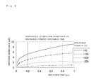
- FIG. 4 is a view illustrating a relationship among the discharge time, the discharge current, and the diffusion resistance at a predetermined temperature.
- the diffusion resistance becomes large as the discharge time becomes long, and becomes large as the current becomes small.
- the diffusion resistance at the predetermined temperature for example, 25° C.
- this found diffusion resistance is corrected in accordance with the temperature of the secondary battery 14 , a value of the diffusion resistance obtained by the correction is added to a value of the internal resistance found by the pulse-discharge by the discharge circuit 15 at the stop time of the engine 17 , the obtained value is substituted to the above-stated expression (1), and thereby, an accurate starting voltage is found.
- FIG. 5 is a flowchart to explain an example of a process executed in the embodiment illustrated in FIG. 1 .
- the flowchart illustrated in FIG. 5 is executed at a predetermined cycle (for example, every several hours or every several days) when the engine 17 stops.
- a predetermined cycle for example, every several hours or every several days
- step S 1 the CPU 10 a makes the secondary battery 14 perform pulse-discharge by on/off controlling the discharge circuit 15 via the I/F 10 f .
- the secondary battery 14 is discharged by a rectangular pulse having a pulse width of millisecond order. It goes without saying that the pulse width may be ones other than the above.
- step S 2 the CPU 10 a acquires a voltage V and a current I at the pulse-discharge time by the voltage sensor 11 and the current sensor 12 .
- step S 3 the CPU 10 a determines whether or not the pulse-discharge is performed for a predetermined number of times, when it is determined that the predetermined number of times of pulse-discharges are performed (step S 3 : Yes), the process goes to step S 4 , and in other cases (step S 3 : No), the process returns to the step S 1 to repeat the similar processes as the case as stated above. For example, when the pulse-discharges are repeated for several dozen times, the process goes to the step S 4 . It goes without saying that the number of times may be ones other than the above.
- the pulse-discharges of the secondary battery 14 are performed for the predetermined number of times by the discharge circuit 15 by the processes of the above-stated steps S 1 to S 3 , and the voltages V and the currents I at that times are measured by the voltage sensor 11 and the current sensor 12 .
- the CPU 10 a finds an internal resistance R of the secondary battery 14 based on the voltages V and the currents I of the secondary battery 14 at the pulse-discharge times measured in the repeating processes of the steps S 1 to S 3 .
- the internal resistance R found as stated above corresponds to the conductor resistance and the positive/negative reaction resistance illustrated in FIG. 6 .
- step S 5 the CPU 10 a acquires a starting time discharge current Id.
- the starting time discharge current is, for example, an average value of the currents supplied from the secondary battery 14 to the starter motor 18 at the starting time of the engine 17 .
- the CPU 10 a measures the starting time discharge current by the current sensor 12 at the starting time of the engine 17 , and stores it as the parameter 10 ca of the RAM 10 c .
- the CPU 10 a acquires the starting time discharge current Id stored at the RAM 10 c . Note that an average value of the discharge currents at plural starting times may be used as the starting time discharge current Id.
- step S 6 the CPU 10 a acquires a starting time discharge time Td.
- the starting time discharge time is a time for which, for example, the current is supplied from the secondary battery 14 to the starter motor 18 at the starting time of the engine 17 .
- the CPU 10 a measures the starting time discharge time by the timer 10 d at the starting time of the engine 17 , and stores it as the parameter 10 ca of the RAM 10 c .
- the CPU 10 a acquires the starting time discharge time Td stored at the RAM 10 c . Note that an average value of starting times at the plural number of starting times may be used as the starting time discharge time Td.
- step S 7 the CPU 10 a calculates a diffusion resistance Rd based on the starting time discharge current Id and the starting time discharge time Td acquired at the steps S 5 , S 6 .
- the CPU 10 a stores a table or a relational expression representing the relationship among the discharge current, the discharge time and the diffusion resistance at the predetermined temperature (for example, 25° C.) illustrated in FIG. 4 , as the parameter 10 ca of the RAM 10 c , and acquires a value of the diffusion resistance Rd corresponding to the starting time discharge current Id and the starting time discharge time Td acquired at the steps S 5 , S 6 from the table or the relational expression.
- step S 8 the CPU 10 a acquires a temperature Tc of the secondary battery 14 in itself or the peripheral temperature thereof by the temperature sensor 13 .
- step S 9 the CPU 10 a corrects the value of the diffusion resistance Rd calculated at the step S 7 based on the temperature Tc acquired at the step S 8 .
- a table or a relational expression representing a relationship between the temperature Tc and the diffusion resistance Rd is stored as the parameter 10 ca of the RAM 10 c to correct the value of the diffusion resistance Rd found at the step S 7 based on the temperature Tc acquired at the step S 8 .
- step S 10 the CPU 10 a adds the value of the diffusion resistance Rd which is temperature corrected at the step S 9 to the value of the internal resistance R found at the step S 4 , and newly stores the obtained value as the internal resistance R.
- the internal resistance R thereby becomes a value in which the diffusion resistance Rd is added.
- step S 11 the CPU 10 a acquires a voltage before starting Vb.
- the voltage before starting is a voltage of the secondary battery 14 before the engine 17 is started.
- the CPU 10 a measures the voltage before the engine 17 is started by the voltage sensor 11 , and stores as the parameter 10 ca of the RAM 10 c .
- the CPU 10 a acquires the voltage before starting Vb stored at the RAM 10 c . Note that, for example, a voltage at a timing when a most recent discharge current is approximately “0” (zero) A, or a stable voltage estimated value may be used as the voltage before starting.
- the starting voltage Vs is found based on the value of the internal resistance R obtained by adding the diffusion resistance Rd generated resulting from the current flowing in the starter motor 18 at the starting time to the internal resistance R by the above-stated processes, and therefore, it is possible to accurately find the starting voltage Vs.
- the temperature whose variation is relatively large is set as a fixed value, and the diffusion resistance is found based on the starting time discharge current and the starting time discharge time whose variations are small, and the found diffusion resistance is corrected based on an actually measured temperature, and therefore, it is possible to speed-up the process by simplifying the calculation.
- the internal resistance R excluding the diffusion resistance Rd which is not affected by deterioration of the secondary battery 14 illustrated in FIG. 6 is found, and based on the internal resistance R, the internal resistance suitable for the estimation of the starting voltage is calculated based on a sum with the diffusion resistance (R+Rd) based on the internal resistance R. It is thereby possible to enable both an accurate deterioration detection of the secondary battery 14 by using the former internal resistance R and an accurate estimation of the starting voltage by using the latter internal resistance (R+Rd) in which the diffusion resistance Rd is taken into account.
- the internal resistance R is found by the pulse-discharge, but it may be found by a method other than the above. Specifically, for example, it is also possible to make the alternating current flow in the secondary battery 14 , and find the internal resistance based on a voltage at that time.
- the temperature Tc is fixed at the predetermined value
- the diffusion resistance Rd is found based on the acquired starting time discharge current Id and the starting time discharge time Td.
- one of the starting time discharge current Id and the starting time discharge time Td may be fixed at a predetermined value
- the diffusion resistance Rd is found based on a table or a relational expression representing a relationship between the other one and the temperature Tc, and thereafter, a correction is performed based on a parameter to be the fixed value.
- the starting time discharge current Id is fixed at a predetermined value
- the diffusion resistance Rd is found based on a table or a relational expression representing a relationship between the starting time discharge time Td and the temperature Tc, and a found value is corrected based on a measurement value of the starting time discharge current Id.
- the diffusion resistance Rd is found based on a table or a relational expression representing a relationship between the starting time discharge current Id and the temperature Tc, and a found value is corrected based on a measurement value of the starting time discharge time Td.
- one parameter is fixed, but for example, the diffusion resistance Rd is found by fixing two parameters at predetermined values, and the diffusion resistance Rd may be corrected based on actually measured values of the fixed parameters.
- a maximum current and time estimated in each vehicle may be used as the starting time discharge current and the starting time discharge time. In such a case, it is possible to further simplify the processes.
Landscapes
- Physics & Mathematics (AREA)
- General Physics & Mathematics (AREA)
- Engineering & Computer Science (AREA)
- Power Engineering (AREA)
- Chemical & Material Sciences (AREA)
- Chemical Kinetics & Catalysis (AREA)
- Manufacturing & Machinery (AREA)
- Electrochemistry (AREA)
- General Chemical & Material Sciences (AREA)
- Mechanical Engineering (AREA)
- General Engineering & Computer Science (AREA)
- Combustion & Propulsion (AREA)
- Secondary Cells (AREA)
- Tests Of Electric Status Of Batteries (AREA)
- Charge And Discharge Circuits For Batteries Or The Like (AREA)
Abstract
Description
Starting voltage=Voltage before starting+Starting current×Internal resistance (1)
Claims (13)
Applications Claiming Priority (3)
| Application Number | Priority Date | Filing Date | Title |
|---|---|---|---|
| JP2012047442A JP5684172B2 (en) | 2012-03-03 | 2012-03-03 | Secondary battery state detection device and secondary battery state detection method |
| JP2012-047442 | 2012-03-03 | ||
| PCT/JP2013/055741 WO2013133184A1 (en) | 2012-03-03 | 2013-03-01 | Secondary battery state detection device and secondary battery state detection method |
Related Parent Applications (1)
| Application Number | Title | Priority Date | Filing Date |
|---|---|---|---|
| PCT/JP2013/055741 Continuation WO2013133184A1 (en) | 2012-03-03 | 2013-03-01 | Secondary battery state detection device and secondary battery state detection method |
Publications (2)
| Publication Number | Publication Date |
|---|---|
| US20140347059A1 US20140347059A1 (en) | 2014-11-27 |
| US10451683B2 true US10451683B2 (en) | 2019-10-22 |
Family
ID=49116664
Family Applications (1)
| Application Number | Title | Priority Date | Filing Date |
|---|---|---|---|
| US14/449,641 Active 2035-07-21 US10451683B2 (en) | 2012-03-03 | 2014-08-01 | Secondary battery state detection device and secondary battery state detection method |
Country Status (6)
| Country | Link |
|---|---|
| US (1) | US10451683B2 (en) |
| EP (1) | EP2778701B1 (en) |
| JP (1) | JP5684172B2 (en) |
| KR (1) | KR101563178B1 (en) |
| CN (1) | CN103917885B (en) |
| WO (1) | WO2013133184A1 (en) |
Families Citing this family (11)
| Publication number | Priority date | Publication date | Assignee | Title |
|---|---|---|---|---|
| US20160023567A1 (en) * | 2014-07-28 | 2016-01-28 | Ford Global Technologies, Llc | Temperature dependent electrochemical battery model for vehicle control |
| CN107533108B (en) * | 2015-03-27 | 2020-03-06 | 松下知识产权经营株式会社 | State estimation device and state estimation method for secondary battery |
| KR102181918B1 (en) * | 2015-08-06 | 2020-11-23 | 가부시키가이샤 무라타 세이사쿠쇼 | Secondary battery charging method, charge control device, and secondary battery |
| US10137797B2 (en) * | 2015-09-28 | 2018-11-27 | Ford Global Technologies, Llc | Battery state of charge estimation based on current pulse duration |
| JP6883742B2 (en) * | 2016-09-16 | 2021-06-09 | パナソニックIpマネジメント株式会社 | Battery diagnostic methods, battery diagnostic programs, battery management devices, and power storage systems |
| TWI618330B (en) * | 2016-10-28 | 2018-03-11 | 財團法人工業技術研究院 | Electronic device, battery module and charging and discharging method |
| KR102805832B1 (en) | 2017-01-18 | 2025-05-12 | 삼성전자주식회사 | Method and apparatus for managing battery |
| JP6548699B2 (en) * | 2017-08-03 | 2019-07-24 | 本田技研工業株式会社 | Power supply system |
| JP7606290B2 (en) * | 2020-08-19 | 2024-12-25 | 株式会社Subaru | Vehicle control device |
| KR20220060707A (en) * | 2020-11-05 | 2022-05-12 | 현대자동차주식회사 | Vehicle and control method thereof |
| CN114200309B (en) * | 2021-12-08 | 2024-01-09 | 广州小鹏汽车科技有限公司 | Simulation test methods, devices, vehicles and storage media for vehicle batteries |
Citations (8)
| Publication number | Priority date | Publication date | Assignee | Title |
|---|---|---|---|---|
| US6646419B1 (en) * | 2002-05-15 | 2003-11-11 | General Motors Corporation | State of charge algorithm for lead-acid battery in a hybrid electric vehicle |
| JP2006284537A (en) | 2005-04-05 | 2006-10-19 | Furukawa Electric Co Ltd:The | Battery deterioration state determination method, deterioration determination device, and power supply system |
| JP2007179968A (en) | 2005-12-28 | 2007-07-12 | Auto Network Gijutsu Kenkyusho:Kk | Battery state management device |
| US20090217897A1 (en) * | 2004-06-29 | 2009-09-03 | Sven Hartmann | Motor vehicle energy management having a supplementary starter diagnostic function |
| JP2009244179A (en) | 2008-03-31 | 2009-10-22 | Furukawa Electric Co Ltd:The | Battery discharge duration prediction method, battery status detection method, battery status detection system, and battery power source system |
| US20100250038A1 (en) * | 2009-03-30 | 2010-09-30 | Tomokazu Morita | Battery measuring device, battery control system and vehicle |
| JP2011015520A (en) * | 2009-07-01 | 2011-01-20 | Toyota Motor Corp | Control device of vehicle |
| US20120290234A1 (en) * | 2011-05-13 | 2012-11-15 | Gm Global Technology Operations, Llc. | Systems and methods for determining cell capacity values in a multi-cell battery |
Family Cites Families (6)
| Publication number | Priority date | Publication date | Assignee | Title |
|---|---|---|---|---|
| EP1298444A1 (en) * | 2001-09-28 | 2003-04-02 | Johnson Controls Batterien GmbH & Co. KG | Procedure for determining state variables of an accumulator |
| US7081755B2 (en) * | 2002-09-05 | 2006-07-25 | Midtronics, Inc. | Battery tester capable of predicting a discharge voltage/discharge current of a battery |
| JP4807000B2 (en) * | 2005-08-09 | 2011-11-02 | トヨタ自動車株式会社 | Performance degradation determination apparatus and method |
| JP2008058278A (en) * | 2006-09-04 | 2008-03-13 | Toyota Motor Corp | Secondary battery internal state estimation device, secondary battery internal state estimation method, program, and recording medium |
| JP2010270747A (en) * | 2009-04-23 | 2010-12-02 | Denso Corp | Engine automatic control device |
| JP5558941B2 (en) * | 2010-06-30 | 2014-07-23 | 三洋電機株式会社 | How to detect battery internal resistance |
-
2012
- 2012-03-03 JP JP2012047442A patent/JP5684172B2/en active Active
-
2013
- 2013-03-01 EP EP13757320.0A patent/EP2778701B1/en active Active
- 2013-03-01 CN CN201380003751.2A patent/CN103917885B/en active Active
- 2013-03-01 WO PCT/JP2013/055741 patent/WO2013133184A1/en not_active Ceased
- 2013-03-01 KR KR1020147000985A patent/KR101563178B1/en active Active
-
2014
- 2014-08-01 US US14/449,641 patent/US10451683B2/en active Active
Patent Citations (9)
| Publication number | Priority date | Publication date | Assignee | Title |
|---|---|---|---|---|
| US6646419B1 (en) * | 2002-05-15 | 2003-11-11 | General Motors Corporation | State of charge algorithm for lead-acid battery in a hybrid electric vehicle |
| US20090217897A1 (en) * | 2004-06-29 | 2009-09-03 | Sven Hartmann | Motor vehicle energy management having a supplementary starter diagnostic function |
| JP2006284537A (en) | 2005-04-05 | 2006-10-19 | Furukawa Electric Co Ltd:The | Battery deterioration state determination method, deterioration determination device, and power supply system |
| JP2007179968A (en) | 2005-12-28 | 2007-07-12 | Auto Network Gijutsu Kenkyusho:Kk | Battery state management device |
| JP2009244179A (en) | 2008-03-31 | 2009-10-22 | Furukawa Electric Co Ltd:The | Battery discharge duration prediction method, battery status detection method, battery status detection system, and battery power source system |
| US20100250038A1 (en) * | 2009-03-30 | 2010-09-30 | Tomokazu Morita | Battery measuring device, battery control system and vehicle |
| JP2011015520A (en) * | 2009-07-01 | 2011-01-20 | Toyota Motor Corp | Control device of vehicle |
| US20120109443A1 (en) * | 2009-07-01 | 2012-05-03 | Toyota Jidosha Kabushiki Kaisha | Control system of vehicle |
| US20120290234A1 (en) * | 2011-05-13 | 2012-11-15 | Gm Global Technology Operations, Llc. | Systems and methods for determining cell capacity values in a multi-cell battery |
Non-Patent Citations (1)
| Title |
|---|
| International Search Report for PCT Application No. PCT/JP2013/055741, dated May 14, 2013, 2 pages. |
Also Published As
| Publication number | Publication date |
|---|---|
| JP2013181928A (en) | 2013-09-12 |
| CN103917885A (en) | 2014-07-09 |
| CN103917885B (en) | 2016-05-25 |
| WO2013133184A1 (en) | 2013-09-12 |
| US20140347059A1 (en) | 2014-11-27 |
| KR101563178B1 (en) | 2015-10-26 |
| JP5684172B2 (en) | 2015-03-11 |
| EP2778701A4 (en) | 2015-10-21 |
| KR20140053097A (en) | 2014-05-07 |
| EP2778701B1 (en) | 2019-07-24 |
| EP2778701A1 (en) | 2014-09-17 |
Similar Documents
| Publication | Publication Date | Title |
|---|---|---|
| US10451683B2 (en) | Secondary battery state detection device and secondary battery state detection method | |
| US10656210B2 (en) | Secondary battery state detection device and secondary battery state detection method | |
| US11796600B2 (en) | Chargeable battery abnormality detection apparatus and chargeable battery abnormality detection method | |
| CN108885242B (en) | Secondary battery degradation estimation device and secondary battery degradation estimation method | |
| US11022653B2 (en) | Deterioration degree estimation device and deterioration degree estimation method | |
| JP5598869B2 (en) | Secondary battery state detection device and secondary battery state detection method | |
| US20170012327A1 (en) | Secondary battery internal temperature estimation device and secondary battery internal temperature estimation method | |
| CN103238081B (en) | Secondary cell condition checkout gear and secondary cell condition detection method | |
| JP2014105995A (en) | Secondary battery state estimation apparatus and method | |
| EP3518376A1 (en) | Secondary battery state detection device and secondary battery state detection method | |
| US8949007B2 (en) | Start-up possibility determining apparatus and start-up possibility determining method | |
| JP2015215272A (en) | Secondary battery state detection device and secondary battery state detection method | |
| US10481212B2 (en) | Secondary battery status estimation device and status estimation method | |
| JP2019117711A (en) | Rechargeable battery liquid reduction detecting device and rechargeable battery liquid reduction detecting method | |
| JP2014238379A (en) | Secondary battery state detector | |
| JP6210552B2 (en) | Secondary battery state detection device and secondary battery state detection method | |
| US9116213B2 (en) | Secondary battery state detecting device and secondary battery state detecting method | |
| JP2013101076A (en) | Internal resistance measuring apparatus and internal resistance measurement method | |
| JP2019138673A (en) | Rechargeable battery state detector and rechargeable battery state detection method | |
| US20160103182A1 (en) | Secondary battery status detection device and secondary battery status detection method |
Legal Events
| Date | Code | Title | Description |
|---|---|---|---|
| AS | Assignment |
Owner name: FURUKAWA ELECTRIC CO., LTD., JAPAN Free format text: ASSIGNMENT OF ASSIGNORS INTEREST;ASSIGNORS:SATO, ETSUZO;SUGIMURA, TAKEZO;WATANABE, YUICHI;SIGNING DATES FROM 20140530 TO 20140603;REEL/FRAME:033446/0219 Owner name: FURUKAWA AUTOMOTIVE SYSTEMS INC., JAPAN Free format text: ASSIGNMENT OF ASSIGNORS INTEREST;ASSIGNORS:SATO, ETSUZO;SUGIMURA, TAKEZO;WATANABE, YUICHI;SIGNING DATES FROM 20140530 TO 20140603;REEL/FRAME:033446/0219 |
|
| STPP | Information on status: patent application and granting procedure in general |
Free format text: FINAL REJECTION MAILED |
|
| STPP | Information on status: patent application and granting procedure in general |
Free format text: RESPONSE AFTER FINAL ACTION FORWARDED TO EXAMINER |
|
| STPP | Information on status: patent application and granting procedure in general |
Free format text: DOCKETED NEW CASE - READY FOR EXAMINATION |
|
| STPP | Information on status: patent application and granting procedure in general |
Free format text: NOTICE OF ALLOWANCE MAILED -- APPLICATION RECEIVED IN OFFICE OF PUBLICATIONS |
|
| STPP | Information on status: patent application and granting procedure in general |
Free format text: PUBLICATIONS -- ISSUE FEE PAYMENT RECEIVED |
|
| STCF | Information on status: patent grant |
Free format text: PATENTED CASE |
|
| MAFP | Maintenance fee payment |
Free format text: PAYMENT OF MAINTENANCE FEE, 4TH YEAR, LARGE ENTITY (ORIGINAL EVENT CODE: M1551); ENTITY STATUS OF PATENT OWNER: LARGE ENTITY Year of fee payment: 4 |