US10451269B2 - System and method for supporting a boiler load - Google Patents
System and method for supporting a boiler load Download PDFInfo
- Publication number
- US10451269B2 US10451269B2 US15/075,710 US201615075710A US10451269B2 US 10451269 B2 US10451269 B2 US 10451269B2 US 201615075710 A US201615075710 A US 201615075710A US 10451269 B2 US10451269 B2 US 10451269B2
- Authority
- US
- United States
- Prior art keywords
- support
- boiler
- support leg
- mounting block
- spring
- Prior art date
- Legal status (The legal status is an assumption and is not a legal conclusion. Google has not performed a legal analysis and makes no representation as to the accuracy of the status listed.)
- Active, expires
Links
Images


Classifications
-
- F—MECHANICAL ENGINEERING; LIGHTING; HEATING; WEAPONS; BLASTING
- F22—STEAM GENERATION
- F22B—METHODS OF STEAM GENERATION; STEAM BOILERS
- F22B37/00—Component parts or details of steam boilers
- F22B37/02—Component parts or details of steam boilers applicable to more than one kind or type of steam boiler
- F22B37/10—Water tubes; Accessories therefor
- F22B37/20—Supporting arrangements, e.g. for securing water-tube sets
- F22B37/208—Backstay arrangements
-
- F—MECHANICAL ENGINEERING; LIGHTING; HEATING; WEAPONS; BLASTING
- F22—STEAM GENERATION
- F22B—METHODS OF STEAM GENERATION; STEAM BOILERS
- F22B37/00—Component parts or details of steam boilers
- F22B37/02—Component parts or details of steam boilers applicable to more than one kind or type of steam boiler
- F22B37/24—Supporting, suspending or setting arrangements, e.g. heat shielding
- F22B37/244—Supporting, suspending or setting arrangements, e.g. heat shielding for water-tube steam generators suspended from the top
Definitions
- Embodiments of the invention relate generally to power generation systems and, more particularly, to a system and method for supporting a boiler load.
- Steam boiler plants generally have large furnaces which are commonly constructed of a number of water-cooled tubes welded in side-by-side arrangement to form gas tight tube banks forming the walls of the furnace. Boilers may be supported from the bottom, middle, or top depending on, for example, the particular application and the size of the boiler. Typically, package boilers, pre-engineered oil- and gas-fired boilers, and solid fuel-fired boilers up to about 60 tph can be bottom-supported. In a bottom-support design, a supporting structure is utilized to support the weight of the boiler from below, and expansion of the boiler pressure parts and hot structural parts occurs upward.
- top-support designs are typically employed.
- Top-support designs can be likened to a church bell, whereby all pressure parts and other components are suspended from structural members (e.g., girders) of the steam generating plant.
- structural members e.g., girders
- these buckstays are disposed in bands around the perimeter of the furnace walls at vertically spaced intervals throughout the height of the furnace.
- the buckstays on opposite walls of the furnace are interconnected through buckstay ties so that the reactions of one buckstay are resisted by the reactions of the buckstay on the opposing wall so as to counteract the pressure forces acting on the furnace walls.
- vertical support members to interconnect each buckstay to its upper and lower neighbors with a connection that permits a sliding action which is required due to relative movement between the furnace tube walls to which each buckstay is connected and the buckstays themselves.
- a support system for a boiler includes a plurality of support assemblies arranged intermediate a ground surface and the boiler.
- Each of the support assemblies include a first support leg having a lower end operatively connected to the ground surface and an upper end operatively connected to the boiler, a second support leg having a lower end operatively connected to the ground surface and an upper end operatively connected to the boiler, and at least one spring operatively connected to the first support leg and the second support leg and extending horizontally between the first support leg and the second support leg.
- a support assembly for a boiler in another embodiment, includes a first support member extending vertically between a ground surface and the boiler, a second support member extending vertically between the ground surface and the boiler and spaced from the first support member, and at least one spring extending intermediate the first support member and the second support member.
- a method for supporting a boiler load includes the steps of arranging a first support leg between a ground surface and the boiler, arranging a second support leg between the ground surface and the boiler, and interconnecting the first and second support leg with a variable spring.
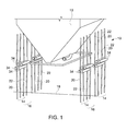
- FIG. 1 is a perspective view of a support system for a boiler, according to an embodiment of the invention.
- FIG. 2 is a simplified, schematic illustration of a single support assembly of the support system of FIG. 1 .
- FIG. 3 is a perspective view of a mounting block of the support assembly of FIG. 1 .
- FIG. 4 is a top plan view of the mounting block of FIG. 3 .
- FIG. 5 is a partial cross-sectional view of the mounting block, taken along line A-A of FIG. 4 .
- FIG. 6 is a partial cross-sectional view of the mounting block, taken along line B-B of FIG. 4 .
- FIG. 7 is a cross-sectional illustration of a spring of the support assembly of FIG. 1 .
- FIG. 8 is a detail, perspective view of a portion of the support system of FIG. 1 , illustrating nesting of various support assemblies.
- FIG. 9 is a simplified, side elevational view of the support system of FIG. 1 , illustrating the system in unloaded and loaded conditions.
- FIG. 10 is a schematic illustration of a first type of horizontal supporting tie of the support system of FIG. 1 .
- FIG. 11 is a schematic illustration of a second type of a horizontal supporting tie of the support system of FIG. 1 .
- FIG. 12 is a perspective view of a support system for a boiler, according to another embodiment of the invention.
- top-supported refers to a component(s), assembly or apparatus that is supported from the top (e.g., suspended from a support located above).
- middle- or girdle-supported refers to such component(s), assembly or apparatus that is supported at some mid point of such component(s), assembly or apparatus.
- bottom-supported refers to such component(s), assembly or apparatus that is supported from below.
- Embodiments of the invention relate to a system and method for supporting a boiler load from below.
- a support system 10 for a boiler 12 according to an exemplary embodiment is illustrated. While the boiler 12 supported by the system 10 is described herein as being a top-supported boiler (i.e., it is suspended from a support means located thereabove and permitted to expand downwardly under weighted or thermal load), the support system 10 may also be used in connection with a middle-support and even bottom-supported boiler without departing from the broader aspects of the present invention.
- the system 10 includes a plurality of support assemblies 14 , 16 arranged beneath the boiler 12 in nested pairs, as discussed in detail hereinafter.
- the support assemblies 14 , 16 extend from a ground surface 18 to the boiler 12 or other component attached to the boiler 12 , such as a buckstay.
- the support assemblies 14 , 16 may be arranged in opposing rows beneath the boiler 12 , as illustrated in FIG. 1 .
- Each support assembly 14 includes a first support leg/member 20 and a second support leg/member 22 spaced from the first support leg 20 .
- Each support leg 20 , 22 has a lower end 24 operatively connected to the ground surface 18 and an upper end 26 operatively connected to the boiler 12 .
- the legs 20 , 22 may be connected to the ground surface 18 and boiler 12 via any means known in the art that allows slight pivotal movement of the legs 20 , 22 at the connection point.
- each support leg 20 , 22 is actually a two-piece part, having an upper strut 28 and a lower strut 30 that are pivotally coupled to one another at their respective distal ends (a midpoint along each leg 20 , 22 ) by a mounting block or bracket 32 .
- the upper and lower struts 28 , 30 are substantially equal in length, although in some embodiments the struts 28 , 30 may differ in length.
- the struts 28 , 30 are each approximately 9,014 inches in length and are formed from a length of 8-inch diameter metal pipe. As further shown in FIG.
- a pair of springs 34 extend between the mounting blocks 32 of each leg 20 , 22 and effectively tether the support legs 20 , 22 of the support assembly 14 to one another.
- the springs 34 are coupled to opposed ends of the mounting block 32 and extend substantially horizontally between the blocks 32 of the respective support legs 20 , 22 .
- the mounting block 32 is an elongated member having an open central portion 36 configured to receive the opposed distal ends of the upper and lower struts 28 , 30 of one of the support legs (such as support leg 20 ) therein.
- Opposed lateral sides of the central portion 36 have apertures 38 configured to receive a threaded bolt or like fastener therethrough to pivotally secure the upper and lower struts 28 , 30 to the mounting block 32 .
- the distal ends of the upper and lower struts 28 , 30 may be formed as a flat plate having an aperture therethrough.
- the apertures in the ends of the struts 28 , 30 may be aligned with the apertures 38 in the central portion 36 of the mounting block 32 , and a suitable fastener (e.g., a threaded fastener or pin) may be passed through the apertures in order to secure the mounting block 32 and struts 28 , 30 to one another.
- a suitable fastener e.g., a threaded fastener or pin
- the upper and lower struts 28 , 30 are permitted to pivot relative to one another about the pin (not shown).
- the mounting block 32 has a pair of opposed apertures 40 in a front face 42 thereof which are utilized to secure the springs 34 to the mounting block 32 .
- the apertures 40 are threaded apertures configured to receive a corresponding threaded portion of the springs 34 , as discussed in detail hereinafter.
- the spring 34 is a variable spring that may have any configuration generally known in the art.
- the spring 34 includes a cylindrical body 44 having end plates 46 fastened to the body 44 at opposed ends thereof.
- a rod 48 extends through an aperture formed in one of the end plates 46 and into the cylindrical body 44 , and terminates just short of the opposing end plate 46 .
- the end of the rod 48 includes a threaded portions 50 configured to be received by the corresponding threaded apertures 40 in the mounting block 32 , as discussed above.
- An opposite end of the spring 34 includes a second rod 51 attached to the end plate 46 with another threaded portion 53 likewise configured to be received by the threaded apertures 40 in the mounting block 32 , enabling mounting of the spring 34 .
- the interior of the pipe 44 is divided into a plurality of distinct sections by interior plates or baffles 52 . Within each section is arranged a coil spring 54 .
- the cylindrical body 44 is a 24-inch (610 mm) diameter metal pipe having a length of approximately 211 inches (5360 mm), and the rod is a 2-inch (50 mm) metal rod.
- the coil springs 54 are approximately 60 inches in height, when uncompressed.
- a nut 55 is provided that allows the springs 54 within the compartments to be selectively compressed.
- the nested configuration of the support assemblies 14 , 16 is shown.
- the support assemblies 14 , 16 overlap one another such that, for example, the first support leg 20 of the second support assembly 16 is received between the springs 34 of the first support assembly 14 (i.e., between the first and second legs 20 , 22 of the first support assembly 14 ).
- the second support leg 22 of the first support assembly 14 is likewise received between the springs 34 of the second support assembly 16 (i.e., between the first and second legs 20 , 22 of the second support assembly 16 ).
- the springs 34 of the second support assembly 16 may be positioned at a vertical height that is different from the vertical height of the springs 34 of the first support assembly 14 , as shown in FIGS. 1 and 8 .
- This nested arrangement permits double the number of support assemblies to be positioned beneath the boiler 12 than would otherwise be possible utilizing a non-nested arrangement, thereby providing twice the support than such non-nested arrangement.
- the support system 10 is arranged between the ground surface 18 and the boiler and is operatively connected to the boiler such as, for example, to a buckstay 60 of the boiler.
- the support system 10 functions to provide auxiliary or bolstering support from below, while the top supports provide support for the weight of the boiler from above (or middle supports wherein the boiler is a middle-supported boiler).
- the struts 28 , 30 of each support leg 20 , 22 provide support to the boiler through the buckstay 60 , which may be needed to support added weight due to, for example, the accumulation of bottom ash in the bottom of the boiler.
- the support system 10 may be retrofit onto existing top- or middle-supported boilers to provide bolstering support where it is desired to store more bottom ash within the boiler (which increases the weight/load that must be carried).
- reference numerals 20 and 22 represent the position of the legs in an unloaded condition
- reference numerals 20 ′ and 22 ′ represent the position of the legs in a loaded position resulting from downward thermal expansion of the boiler 12 and/or additional weighted load due to the accumulation of bottom ash.
- the springs 34 resist such movement, providing a constant supporting load (as downward movement of the boiler increases, the spring load correspondingly increases).
- the support assembly 10 may also include a plurality of horizontal ties between each support assembly 14 , 16 and the main boiler support structure (not shown). These ties are configured to ensure that the buckling length of each strut is equal to the length of the strut, rather than the full distance from the ground surface 18 to the buckstay 60 .
- the ties are configured to provide horizontal, out of plane stability for each of the support assemblies 14 , 16 .
- “out of plane” means at an angle to a plane extending through the first and second support legs 20 , 22 of each support assembly 14 , 16 (e.g., perpendicular to the spring axis). As illustrated in FIGS.
- a first tie 62 is utilized to provide out of plane stability for non-nested portions of the springs 34
- a second tie 64 is utilized to provide out of plane stability for the nested portions of the springs 34
- FIG. 10 more particularly illustrates the configuration of tie 62 as attached to the main boiler support structure 66
- FIG. 11 more particularly illustrates the configuration of tie 64 as attached to the main boiler support structure 66 .
- FIG. 12 a support system 100 according to another embodiment of the invention is illustrated.
- the support system 100 is similar to support system 10 , where like reference numerals designate like parts.
- Support system 100 does not, however, utilized nested support assemblies, but rather utilized spaced-apart support assemblies 14 having a configuration identical to support assemblies 14 discussed above.
- ties 110 connected to variable springs 34 and building steel e.g., main boiler support structure
- building steel e.g., main boiler support structure
- the support system 10 , 100 of the present invention therefore provides bottom bolstering support for a top-supported boiler, which maintains allowance for downward thermal expansion of the boiler and/or components thereof. This may be particularly desirable where a significant amount of bottom ash storage capacity is desired in top-supported boilers.
- the support system 10 of the invention may therefore serve to reduce the cost of buckstay systems, pressure part support straps, pressure part hangers, and building steel (which heretofore had to be redesigned to accommodate additional load due to bottom ash storage). In connection with this, a reduction in pressure part hanging straps provides more flexibility for installing observation ports, burners, over-fire wind boxes, sootblowers and the like.
- a support system for a boiler includes a plurality of support assemblies arranged intermediate a ground surface and the boiler.
- Each of the support assemblies include a first support leg having a lower end operatively connected to the ground surface and an upper end operatively connected to the boiler, a second support leg having a lower end operatively connected to the ground surface and an upper end operatively connected to the boiler, and at least one spring operatively connected to the first support leg and the second support leg and extending generally horizontally between the first support leg and the second support leg.
- the first and second support legs each include a lower strut having the lower end and an upper strut having the upper end. The upper and lower struts of each support leg are pivotally connected to one another.
- each support assembly further includes a first mounting block connecting the lower strut of the first leg to the upper strut of the first leg, and a second mounting block connecting the lower strut of the second leg to the upper strut of the second leg.
- the spring extends between the first mounting block and the second mounting block.
- the spring is a pair of springs.
- the springs are laterally offset from a plane extending through the first and second support legs.
- the spring is a variable spring.
- at least one of the plurality of support assemblies is nested with at least another of the plurality of support assemblies.
- the upper ends of the first and second support legs are connected to a buckstay of the boiler.
- the boiler is a top-supported boiler having a plurality of pressure parts suspended from a structural member located above the pressure parts.
- the support system may include at least one tie operatively connected to the spring and to a support, the at least one tie providing horizontal, out-of-plane stability for the support assemblies.
- a support assembly for a boiler includes a first support member extending generally vertically between a ground surface and the boiler, a second support member extending generally vertically between the ground surface and the boiler and spaced from the first support member, and at least one spring extending intermediate the first support member and the second support member.
- the boiler is a top-supported boiler.
- the first and second support members each include a lower strut having a lower end connected to the ground surface and an upper strut having an upper end connected to the boiler, wherein the upper and lower struts of each support member are pivotally connected to one another.
- the support assembly may also include a first mounting block connecting the lower strut of the first member to the upper strut of the first member, and a second mounting block connecting the lower strut of the second member to the upper strut of the second member, wherein spring extends between the first mounting block and the second mounting block.
- the spring is a pair of springs, and the springs may be variable springs.
- the upper ends of the upper struts are connected to a buckstay of the boiler.
- a method for supporting a boiler load includes the steps of arranging a first support leg between a ground surface and the boiler, arranging a second support leg between the ground surface and the boiler, and interconnecting the first and second support leg with a variable spring.
- the first and second support legs each include a lower strut having a lower end connected to the ground surface and an upper strut having an upper end connected to the boiler, wherein the upper and lower struts of each support leg are pivotally connected to one another.
- the method may further include the step of placing the variable spring in compression.
- the variable spring is a pair of variable springs.
- the boiler is a top-supported boiler, and the boiler load results from at least one of bottom ash accumulation in the boiler and downward thermal expansion of the boiler.
Landscapes
- Engineering & Computer Science (AREA)
- Physics & Mathematics (AREA)
- Thermal Sciences (AREA)
- Mechanical Engineering (AREA)
- General Engineering & Computer Science (AREA)
- Fluidized-Bed Combustion And Resonant Combustion (AREA)
- Vibration Prevention Devices (AREA)
- Solid-Fuel Combustion (AREA)
- Conveying And Assembling Of Building Elements In Situ (AREA)
Abstract
Description
Claims (17)
Priority Applications (5)
| Application Number | Priority Date | Filing Date | Title |
|---|---|---|---|
| US15/075,710 US10451269B2 (en) | 2016-03-21 | 2016-03-21 | System and method for supporting a boiler load |
| PCT/EP2017/056288 WO2017162523A1 (en) | 2016-03-21 | 2017-03-16 | System and method for supporting a boiler load |
| CN201780018583.2A CN108884990B (en) | 2016-03-21 | 2017-03-16 | System and method for supporting boiler loads |
| DE112017001433.6T DE112017001433T5 (en) | 2016-03-21 | 2017-03-16 | SYSTEM AND METHOD FOR SUPPORTING A BOILER LOAD |
| TW106108858A TWI706110B (en) | 2016-03-21 | 2017-03-17 | System and method for supporting a boiler load |
Applications Claiming Priority (1)
| Application Number | Priority Date | Filing Date | Title |
|---|---|---|---|
| US15/075,710 US10451269B2 (en) | 2016-03-21 | 2016-03-21 | System and method for supporting a boiler load |
Publications (2)
| Publication Number | Publication Date |
|---|---|
| US20170268767A1 US20170268767A1 (en) | 2017-09-21 |
| US10451269B2 true US10451269B2 (en) | 2019-10-22 |
Family
ID=58358599
Family Applications (1)
| Application Number | Title | Priority Date | Filing Date |
|---|---|---|---|
| US15/075,710 Active 2036-07-21 US10451269B2 (en) | 2016-03-21 | 2016-03-21 | System and method for supporting a boiler load |
Country Status (5)
| Country | Link |
|---|---|
| US (1) | US10451269B2 (en) |
| CN (1) | CN108884990B (en) |
| DE (1) | DE112017001433T5 (en) |
| TW (1) | TWI706110B (en) |
| WO (1) | WO2017162523A1 (en) |
Families Citing this family (1)
| Publication number | Priority date | Publication date | Assignee | Title |
|---|---|---|---|---|
| CN108844057A (en) * | 2018-09-03 | 2018-11-20 | 浙江杭兴锅炉有限公司 | Boiler supports seat easy to carry |
Citations (15)
| Publication number | Priority date | Publication date | Assignee | Title |
|---|---|---|---|---|
| US1893295A (en) * | 1931-03-07 | 1933-01-03 | Sargent & Lundy | Spring support |
| US2786106A (en) * | 1954-03-10 | 1957-03-19 | Koppers Co Inc | Means for determining the correct positioning of the operating machines of coke oven batteries |
| US3118643A (en) * | 1960-08-09 | 1964-01-21 | Leonard S Suozzo | Spring support |
| US3814063A (en) * | 1973-07-13 | 1974-06-04 | Babcock & Wilcox Ltd | Support of tube walls |
| US4055329A (en) * | 1976-07-19 | 1977-10-25 | Leisure Manufacturing Co., Inc. | Scissors jack |
| US4059075A (en) | 1976-11-08 | 1977-11-22 | Combustion Engineering, Inc. | Buckstay arrangement |
| US4286549A (en) * | 1979-12-03 | 1981-09-01 | Foster Wheeler Energy Corporation | Steam generator support system |
| GB2098707A (en) | 1981-05-14 | 1982-11-24 | Foster Wheeler Energy Corp | Steam generator support system |
| US4589621A (en) * | 1984-01-03 | 1986-05-20 | International Business Machines Corporation | Ergonomic monitor stand |
| US4940025A (en) * | 1989-03-06 | 1990-07-10 | Westinghouse Electric Corp. | Steam generator upper support having thermal displacement compensation |
| US5557901A (en) | 1994-11-15 | 1996-09-24 | The Babcock & Wilcox Company | Boiler buckstay system |
| WO1998028573A1 (en) | 1996-12-23 | 1998-07-02 | Combustion Engineering, Inc. | Field adjustable boltless stirrup |
| US20080271686A1 (en) * | 2007-05-03 | 2008-11-06 | Radke Edward F | Link Type Seismic Tie For Boilers |
| CN201558738U (en) | 2009-11-24 | 2010-08-25 | 鞍钢集团矿业公司 | Vibrating Coal Feeder for Power Plant Boiler Pulverizing System with Vibration Reduction Device |
| CN202054586U (en) | 2011-05-02 | 2011-11-30 | 郭宏鹤 | Multifunctional boiler furnace overhauling platform |
Family Cites Families (4)
| Publication number | Priority date | Publication date | Assignee | Title |
|---|---|---|---|---|
| SE525265C2 (en) * | 2003-10-06 | 2005-01-18 | Anders Bjoerklund | Construction, inspection and repair device for e.g. recovery boiler, comprises platform suspended on cables from vessel roof and assembled from beams and trusses |
| CN1828112A (en) * | 2006-03-27 | 2006-09-06 | 毛学军 | Double-spring balancing type combined vibration damping support-hanger |
| CN201103921Y (en) * | 2007-10-10 | 2008-08-20 | 大连弹簧有限公司 | Non-standard spring support hanging rack |
| CN204165027U (en) * | 2014-11-03 | 2015-02-18 | 上海锅炉厂有限公司 | Crane system is propped up in a kind of boiler wall of variable cross-section tower boiler |
-
2016
- 2016-03-21 US US15/075,710 patent/US10451269B2/en active Active
-
2017
- 2017-03-16 DE DE112017001433.6T patent/DE112017001433T5/en not_active Withdrawn
- 2017-03-16 CN CN201780018583.2A patent/CN108884990B/en active Active
- 2017-03-16 WO PCT/EP2017/056288 patent/WO2017162523A1/en not_active Ceased
- 2017-03-17 TW TW106108858A patent/TWI706110B/en not_active IP Right Cessation
Patent Citations (15)
| Publication number | Priority date | Publication date | Assignee | Title |
|---|---|---|---|---|
| US1893295A (en) * | 1931-03-07 | 1933-01-03 | Sargent & Lundy | Spring support |
| US2786106A (en) * | 1954-03-10 | 1957-03-19 | Koppers Co Inc | Means for determining the correct positioning of the operating machines of coke oven batteries |
| US3118643A (en) * | 1960-08-09 | 1964-01-21 | Leonard S Suozzo | Spring support |
| US3814063A (en) * | 1973-07-13 | 1974-06-04 | Babcock & Wilcox Ltd | Support of tube walls |
| US4055329A (en) * | 1976-07-19 | 1977-10-25 | Leisure Manufacturing Co., Inc. | Scissors jack |
| US4059075A (en) | 1976-11-08 | 1977-11-22 | Combustion Engineering, Inc. | Buckstay arrangement |
| US4286549A (en) * | 1979-12-03 | 1981-09-01 | Foster Wheeler Energy Corporation | Steam generator support system |
| GB2098707A (en) | 1981-05-14 | 1982-11-24 | Foster Wheeler Energy Corp | Steam generator support system |
| US4589621A (en) * | 1984-01-03 | 1986-05-20 | International Business Machines Corporation | Ergonomic monitor stand |
| US4940025A (en) * | 1989-03-06 | 1990-07-10 | Westinghouse Electric Corp. | Steam generator upper support having thermal displacement compensation |
| US5557901A (en) | 1994-11-15 | 1996-09-24 | The Babcock & Wilcox Company | Boiler buckstay system |
| WO1998028573A1 (en) | 1996-12-23 | 1998-07-02 | Combustion Engineering, Inc. | Field adjustable boltless stirrup |
| US20080271686A1 (en) * | 2007-05-03 | 2008-11-06 | Radke Edward F | Link Type Seismic Tie For Boilers |
| CN201558738U (en) | 2009-11-24 | 2010-08-25 | 鞍钢集团矿业公司 | Vibrating Coal Feeder for Power Plant Boiler Pulverizing System with Vibration Reduction Device |
| CN202054586U (en) | 2011-05-02 | 2011-11-30 | 郭宏鹤 | Multifunctional boiler furnace overhauling platform |
Non-Patent Citations (2)
| Title |
|---|
| International Search Report and Written Opinion issued in connection with corresponding PCT Application No. PCT/EP2017/056288 dated Jun. 26, 2017. |
| Moo-Zung Lee, "A Primer on Pipe supports", http://www.machinedesign.com/hydraulics/primer-pipe-supports, Aug. 28, 2013. * |
Also Published As
| Publication number | Publication date |
|---|---|
| US20170268767A1 (en) | 2017-09-21 |
| CN108884990B (en) | 2020-08-11 |
| TWI706110B (en) | 2020-10-01 |
| CN108884990A (en) | 2018-11-23 |
| TW201740057A (en) | 2017-11-16 |
| DE112017001433T5 (en) | 2019-01-03 |
| WO2017162523A1 (en) | 2017-09-28 |
Similar Documents
| Publication | Publication Date | Title |
|---|---|---|
| US3814063A (en) | Support of tube walls | |
| AU2010233625B2 (en) | Thermal power plant | |
| US8393304B2 (en) | Method of and apparatus for supporting walls of a power boiler | |
| US10451269B2 (en) | System and method for supporting a boiler load | |
| US20140227073A1 (en) | Catalyst loading and unloading device and methods therefor | |
| EP3982043B1 (en) | Middle-supported boiler construction | |
| CN111316039B (en) | Boiler system with support structure | |
| EP3311073B1 (en) | Circulating fluidized bed apparatus | |
| DK3130849T3 (en) | Circulating fluid bed furnace | |
| US20180010714A1 (en) | Stacked duct assemblies | |
| BR112020007857B1 (en) | BOILER SYSTEM WITH A SUPPORT CONSTRUCTION |
Legal Events
| Date | Code | Title | Description |
|---|---|---|---|
| AS | Assignment |
Owner name: GENERAL ELECTRIC TECHNOLOGY GMBH, SWITZERLAND Free format text: ASSIGNMENT OF ASSIGNORS INTEREST;ASSIGNOR:BOWIN, DENNIS IRVIN;REEL/FRAME:038049/0816 Effective date: 20160229 |
|
| STPP | Information on status: patent application and granting procedure in general |
Free format text: NOTICE OF ALLOWANCE MAILED -- APPLICATION RECEIVED IN OFFICE OF PUBLICATIONS |
|
| STPP | Information on status: patent application and granting procedure in general |
Free format text: AWAITING TC RESP., ISSUE FEE NOT PAID |
|
| STPP | Information on status: patent application and granting procedure in general |
Free format text: NOTICE OF ALLOWANCE MAILED -- APPLICATION RECEIVED IN OFFICE OF PUBLICATIONS |
|
| STPP | Information on status: patent application and granting procedure in general |
Free format text: PUBLICATIONS -- ISSUE FEE PAYMENT VERIFIED |
|
| STCF | Information on status: patent grant |
Free format text: PATENTED CASE |
|
| AS | Assignment |
Owner name: GENERAL ELECTRIC TECHNOLOGY GMBH, SWITZERLAND Free format text: CHANGE OF ADDRESS;ASSIGNOR:GENERAL ELECTRIC TECHNOLOGY GMBH;REEL/FRAME:057177/0410 Effective date: 20201222 |
|
| MAFP | Maintenance fee payment |
Free format text: PAYMENT OF MAINTENANCE FEE, 4TH YEAR, LARGE ENTITY (ORIGINAL EVENT CODE: M1551); ENTITY STATUS OF PATENT OWNER: LARGE ENTITY Year of fee payment: 4 |