US1045102A - Mechanical movement. - Google Patents
Mechanical movement. Download PDFInfo
- Publication number
- US1045102A US1045102A US61603111A US1911616031A US1045102A US 1045102 A US1045102 A US 1045102A US 61603111 A US61603111 A US 61603111A US 1911616031 A US1911616031 A US 1911616031A US 1045102 A US1045102 A US 1045102A
- Authority
- US
- United States
- Prior art keywords
- shaft
- track
- tracks
- gear wheel
- pause
- Prior art date
- Legal status (The legal status is an assumption and is not a legal conclusion. Google has not performed a legal analysis and makes no representation as to the accuracy of the status listed.)
- Expired - Lifetime
Links
- 230000033001 locomotion Effects 0.000 title description 23
- 241001131688 Coracias garrulus Species 0.000 description 12
- 238000013459 approach Methods 0.000 description 1
- 230000005540 biological transmission Effects 0.000 description 1
- 210000001217 buttock Anatomy 0.000 description 1
- 230000003247 decreasing effect Effects 0.000 description 1
- 230000000694 effects Effects 0.000 description 1
- 239000002783 friction material Substances 0.000 description 1
- 230000008520 organization Effects 0.000 description 1
- 230000035939 shock Effects 0.000 description 1
Images
Classifications
-
- F—MECHANICAL ENGINEERING; LIGHTING; HEATING; WEAPONS; BLASTING
- F16—ENGINEERING ELEMENTS AND UNITS; GENERAL MEASURES FOR PRODUCING AND MAINTAINING EFFECTIVE FUNCTIONING OF MACHINES OR INSTALLATIONS; THERMAL INSULATION IN GENERAL
- F16H—GEARING
- F16H27/00—Step-by-step mechanisms without freewheel members, e.g. Geneva drives
- F16H27/04—Step-by-step mechanisms without freewheel members, e.g. Geneva drives for converting continuous rotation into a step-by-step rotary movement
- F16H27/06—Mechanisms with driving pins in driven slots, e.g. Geneva drives
-
- Y—GENERAL TAGGING OF NEW TECHNOLOGICAL DEVELOPMENTS; GENERAL TAGGING OF CROSS-SECTIONAL TECHNOLOGIES SPANNING OVER SEVERAL SECTIONS OF THE IPC; TECHNICAL SUBJECTS COVERED BY FORMER USPC CROSS-REFERENCE ART COLLECTIONS [XRACs] AND DIGESTS
- Y10—TECHNICAL SUBJECTS COVERED BY FORMER USPC
- Y10T—TECHNICAL SUBJECTS COVERED BY FORMER US CLASSIFICATION
- Y10T74/00—Machine element or mechanism
- Y10T74/19—Gearing
- Y10T74/1987—Rotary bodies
- Y10T74/19879—Geneva
Definitions
- v.the ⁇ intermittently driven' ⁇ element which vhas the form of a shaft that 1s mounted in bearings inthe member 11, and whlch may be connected to any suitable mechanism that is designed to be operated by an intermittent rotary motion.
- - 15 designates a gear wheel which is keyed or otherwise non frotatively secured to the 70 shaft 10.
- Said gear wheel 15 meshes with a second gear wheel 16 which, as herein shown, is keyed to a stub shaft 17 that is' rotatablymounted in-the Vmember 11.
- v v18 designates a disk which is mounted on the shaft 14 and is provided with a hub 19; said disk being secured to the shaft by 'means of a pin 20 extending through the huband shaft.
- @21 'desi nates a track member that -isgse4 'cured to t e innerface of the disk 185 as by lmeans of thev screw bolts'22.
- 'Said track' -lnember is provided with a' plurality of radial channeled'tracks or grooves 235 there. being six of such tracks ⁇ or grooves shown.
- Saidchanneled tracks or grooves are open at their outer ends andare bounded attheir sides by parallel flangesor ribs 24.
- the gear wheel 16 l is provided near. its periphery with astud 27 which carries a loosely mounted roller 28 vthat extends toward and is adapted to travel in said channeled tracks 23.
- the disk 18 is provided with a V-shaped groove 2 91 in Whicha like shaped tWo-part-brake'ele- '-100 Y ment 30, 30 j made of rubber. or other sui t" able -fyielding friction material.
- the brake consisting of the members 30, 30 and the jaws 31, 31 is provided to avoid ⁇ all likelihood of the parts overrunning when the parts are to be brought to rest.
- a mechanical movement comprising a driven element, a series of radial tracks thereon with adjacent tracks connected with each other at their inner ends, a rotary,driv ing element arranged with its axis radially within the periphery of the driven element and a bearing stud arranged eccentrically on the driving 'element to travel through said tracks.
- Mechanism for translating the continuous rotary motion of a driving element into an intermittent rotary motion of p a driven element, with a pause or dwell' between'such intermittent motions comprising a primary shaft with means for rotating the 'j shaft, a secondary shaft, a member thereon having a plurality .of radial tracks which are connected at their inner ends by curved portions, a bearing member rotatinU with and eccentric to the primary sha; and to travel inwardly through one track, around said curved connecting portion and ⁇ outwardly through an adjacent" track, the curved connecting portion between adjacent tracks beingrconcentric to the driven shaft while the bearing roller is passing ardund the same.
- Mechanism for translating the continuous rotary motion of a driving element into an intermittent rotary motion of adriven element, with a pause or dwell between such intermittent motions comprising a primary rotative shaft with means for rotating the shaft, a secondary shaft, a member thereon having a plurality of radial' channeled tracks with side flanges, the ianges of adjacent tracks being joined by a curved co'nnecting flange and a bearing member rotating with and eccentric to the primary shaft and adapted to travel inwardly through o1"ie"'t rackaroundl said curved connecting rib and outwardly through an ad jacent track.
- V Mechanism for translating the continuous rotary motion of a driving element into an intermittent .rotary motion of a driven element, with aopause or dwell between such intermittent motions comprising a driving shaft, a gear wheel thereon, a second shaft, j a gear wheel thereon meshing with the rstj" gear wheel, a third shaft, a member thereon?" ⁇ having a plurality ef radial tracks which are united 'at their inner enlds by curved connecting portions, a bearing member car- 1 ried by the second gear wheel and ecl centric thereto 'and adapted, during each rotation of the said second gear wheel, to
Landscapes
- Engineering & Computer Science (AREA)
- General Engineering & Computer Science (AREA)
- Mechanical Engineering (AREA)
- Transmission Devices (AREA)
Description
comm 'o "am .i @@9111 'hharaetersggof reference 4"fmarked thereon,
Whihfbg'm ofthis specification. gTbilsingenton-relate's "toa novel mechani calfmovemeht for-trans ting the continurt l motion of a second- `rranged to provide dwell aaneen ,the 'intermittent l' Secondary' or 'drivenelen '"ntonadaptable for use in a Wiyf. lllihilles Where Such combined inv mentnmgvemengt and pause or. dwell of laifdliven' 'element required, and 1 have :2 5 intention, practicallyapplied in wappingmaohnejforwrappmg chewmy cfr-pending application for .'agflaled 91# the-24th day 0f' Octo= 9115" the application of the meinovement-tofthfSaid mQhDe., 1t, if edto `give 'intermittent rotation and 1 f iatepauses orldwells to the mecha-v operates fthe folding'- heads 7.1135" 'chf'reeeqft'he f n other article to-be filmed 11118D9911; and- 5tocarry Y the par- 4folded. articles;y ltrom andl dellyer to. another mechanism for completing tflfillslllg. o-the; wra'pp'er about the article, "movement beingdesignedto give the Probier {pause-"01" Welk $1.161. Wrarpleg head when the latter is.x ini-position vto receive 'iii- 01.1 dischargefa, gumfforg' like 'article' and a mm '.Pervf i. 1
i T e inwntion .xconsistaepinY the matters 'j'. after. set forth. andy more articularlyI n l i harem' I i I I? two-part' brake element 1s confined. 1n said out -i'n' .ther appended claims.
' ebein taken Qll--lllheiline-1f1of1`igt 2. 2 issectionalgyiew takenon thellne AS Sheen-.fletes rj, LOUISVILLE, KENTUCKY; A eonPonATIoNor t A i 'l Specication'of Letters'ateiit. :if: pplication filed-March 21, 1 911. ASerial-1to1 gs,v and l tothe 'Lettera Batent, Serial Num.
space. 25 of the; track member. 'Theribs or apped, 'together wthmthe Wrapper pardrawing; .cileszignatea 0F ELGINQ ILLINOIS; ASSIGOR To enmscrnonewnrme maar" 'a shaft which, in the present instance, constitutes, the driven or -prime moving element. It' has the form of a shaft that is mounted mbearings in a suitable support or member 11. 1t may be provided with a belt pulley or other transmission device 12 whereby to rotate the same.
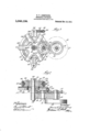
14 designates v.the `intermittently driven' `element, which vhas the form of a shaft that 1s mounted in bearings inthe member 11, and whlch may be connected to any suitable mechanism that is designed to be operated by an intermittent rotary motion.
- 15 designates a gear wheel which is keyed or otherwise non frotatively secured to the 70 shaft 10.' Said gear wheel 15 meshes with a second gear wheel 16 which, as herein shown, is keyed to a stub shaft 17 that is' rotatablymounted in-the Vmember 11.
v v18 designates a disk which is mounted on the shaft 14 and is provided with a hub 19; said disk being secured to the shaft by 'means of a pin 20 extending through the huband shaft.
@21 'desi nates a track member that -isgse4 'cured to t e innerface of the disk 185 as by lmeans of thev screw bolts'22. 'Said track' -lnember is provided with a' plurality of radial channeled'tracks or grooves 235 there. being six of such tracks `or grooves shown. Saidchanneled tracks or grooves are open at their outer ends andare bounded attheir sides by parallel flangesor ribs 24. They vopen 'at their inner ends into a-central open l anges- 240i adjacent radial tracks are connected at their inner ends by Athe curved portions l2 6, constituting continuations of said flanges or' ribs. The gear wheel 16 lis provided near. its periphery with astud 27 which carries a loosely mounted roller 28 vthat extends toward and is adapted to travel in said channeled tracks 23. The disk 18 is provided with a V-shaped groove 2 91 in Whicha like shaped tWo-part-brake'ele- '-100 Y ment 30, 30 j made of rubber. or other sui t" able -fyielding friction material. The sald groovegby'means of the jaws 31, 31 which are pivoted to eachother by means of the pivotf` lin1 .32 whichextends through the hinge" lugs 33 of said jaws. Saidjaws` are` provided `diametrcally- 'opposite the hinge With parallel lugs-341, 34 to one of which 1s latlixed'va' screw-threaded bolt 35 which ex 110 stantially one-half of its revolution said bearing roller. 27 passes from a point at the outer end of one track (the position shown in Fig. 1) to the inner end of the track to impartto saidv track member and the disk 18 and shaft'14 associated therewith a partial rotationin the direction indicated bythe arrow, and during the. latter half of the revolution of said bearing roller v28 lit travels outwardly through the next adja cent lor rear track 23, relatively to the direction of rotation of the track member 21. The speed ofthe driven part, to wit, the shaft 111, is greatest while the bearing roller 28 is traveling through the outer ends of' the tracks, such speed gradually decreasing as the bearing roller approaches the inner ends of the tracks and inallybeing brought to a rest to effect the proper'pause or dwell as the bearing roller passes from one track to an adjacent track. During such time as the bearing roller 28 is `engaged with the curved connecting rib or 'ange 26, the said latter iian e is substantially concentric with the axis 0% rotation of the gear wheel 16 so that, as a result, said bearing roller 28 imarts no movement to the track member. uring this period therefore the movement of said track member and the shaft .14 con nected vtherewith is arrested-to give theI proper pause or dwell to said parts, notwithstanding the continuous movement of the bearing roller 28. in a circular path. As soon 4as the said bearing roller leaves the concentric V'portion of the 'curved connecting rib 26 and moves outwardly into the 51)lneXt rearward channeled track, rotary movement of said track Vmember and, the parts connected therewithy begins and centinues while the bearing roller 1s traveling .outwardly through said track to the outer end thereof and inwardly to the inner end of the latter track. It will thus be seen that the track member and the parts connected to rotate'therewith are brought to a fvery gradual stop or pause and that the movement of said track member is gradually resumed after such pause and gradually accelerated. By reason ofthe fact that the said track member is traveling at its slowest speed just before it is brought to a full stop, there is less likelihood of sa1d adapted track member and the parts rotating therewith overrunning the desired stopping point when brought to rest. Also by reason of`the fact that the parts are brought into motion very gradually after the ,pause or dwell thereof,'there is occasioned no shock or jar when said parts are thus brought into motion, so that the'said secondary or intermittently rotated part may be connected to and operate delicate mechanism without danger of injuring the same.
The brake consisting of the members 30, 30 and the jaws 31, 31 is provided to avoid `all likelihood of the parts overrunning when the parts are to be brought to rest.
In the organization of the mechanism here shown, and which is substantially the arrangement of the mechanism employed in the wrapping machine hereinbefore referred to, it becomes convenient to apply 'the power to the shaft 10. In some instances, however, the shaft 17 may become the primary driven element, with the same results in operation.
'I claim as my invention 1. A mechanical movement comprising a driven element, a series of radial tracks thereon with adjacent tracks connected with each other at their inner ends, a rotary,driv ing element arranged with its axis radially within the periphery of the driven element and a bearing stud arranged eccentrically on the driving 'element to travel through said tracks.
2. Mechanism for translating the continuous rotary motion of a driving element into an intermittent rotary motion of p a driven element, with a pause or dwell' between'such intermittent motions, comprising a primary shaft with means for rotating the 'j shaft, a secondary shaft, a member thereon having a plurality .of radial tracks which are connected at their inner ends by curved portions, a bearing member rotatinU with and eccentric to the primary sha; and to travel inwardly through one track, around said curved connecting portion and `outwardly through an adjacent" track, the curved connecting portion between adjacent tracks beingrconcentric to the driven shaft while the bearing roller is passing ardund the same.
3. Mechanism for translating the continuous rotary motion of a driving element into an intermittent rotary motion of adriven element, with a pause or dwell between such intermittent motions, comprising a primary rotative shaft with means for rotating the shaft, a secondary shaft, a member thereon having a plurality of radial' channeled tracks with side flanges, the ianges of adjacent tracks being joined by a curved co'nnecting flange and a bearing member rotating with and eccentric to the primary shaft and adapted to travel inwardly through o1"ie"'t rackaroundl said curved connecting rib and outwardly through an ad jacent track.
4. Mechanism for'translating the continuous rotary motion of a driving element into 'an intermittent rotary motion of a driven element, with a pause or dwell between such .intermittent 4mot-ions, lcomprising a driving Ftation of the said -second gear wheel, to pass inwardly through one track, around said connecting portion and outwardly through 20v an adjacent track.
5.V Mechanism for translating the continuous rotary motion of a driving element into an intermittent .rotary motion of a driven element, with aopause or dwell between such intermittent motions, comprising a driving shaft, a gear wheel thereon, a second shaft, j a gear wheel thereon meshing with the rstj" gear wheel, a third shaft, a member thereon?"` having a plurality ef radial tracks which are united 'at their inner enlds by curved connecting portions, a bearing member car- 1 ried by the second gear wheel and ecl centric thereto 'and adapted, during each rotation of the said second gear wheel, to
pass inwardly through one track, around said connecting portion and outwardly through an adjacent track, and a brake device associated wi'th the driven shaft to prevent the overrunning of said shaft.
In testimony, that I claim the foregoing as my invention I4 aiix my signature in the vpresence of two witnesses, this 16th day of February A. D. 1911.
' HARRY Y. ARMSTRONG. l
Witnesses:
` WILLIAM L. HALL,
WMAM GOLDBERGER.
Priority Applications (1)
| Application Number | Priority Date | Filing Date | Title |
|---|---|---|---|
| US61603111A US1045102A (en) | 1911-03-21 | 1911-03-21 | Mechanical movement. |
Applications Claiming Priority (1)
| Application Number | Priority Date | Filing Date | Title |
|---|---|---|---|
| US61603111A US1045102A (en) | 1911-03-21 | 1911-03-21 | Mechanical movement. |
Publications (1)
| Publication Number | Publication Date |
|---|---|
| US1045102A true US1045102A (en) | 1912-11-19 |
Family
ID=3113376
Family Applications (1)
| Application Number | Title | Priority Date | Filing Date |
|---|---|---|---|
| US61603111A Expired - Lifetime US1045102A (en) | 1911-03-21 | 1911-03-21 | Mechanical movement. |
Country Status (1)
| Country | Link |
|---|---|
| US (1) | US1045102A (en) |
Cited By (3)
| Publication number | Priority date | Publication date | Assignee | Title |
|---|---|---|---|---|
| US2477105A (en) * | 1947-12-18 | 1949-07-26 | Gleason Works | Index mechanism |
| US2560897A (en) * | 1944-12-11 | 1951-07-17 | Parker Appliance Co | Valve operating means |
| US2851779A (en) * | 1955-05-16 | 1958-09-16 | Joseph B Cox | Angle adjusting means |
-
1911
- 1911-03-21 US US61603111A patent/US1045102A/en not_active Expired - Lifetime
Cited By (3)
| Publication number | Priority date | Publication date | Assignee | Title |
|---|---|---|---|---|
| US2560897A (en) * | 1944-12-11 | 1951-07-17 | Parker Appliance Co | Valve operating means |
| US2477105A (en) * | 1947-12-18 | 1949-07-26 | Gleason Works | Index mechanism |
| US2851779A (en) * | 1955-05-16 | 1958-09-16 | Joseph B Cox | Angle adjusting means |
Similar Documents
| Publication | Publication Date | Title |
|---|---|---|
| US4788882A (en) | Flywheel | |
| US2449852A (en) | Gear drive for printing and other machines | |
| GB1313984A (en) | Imbalanced braking device | |
| US1175300A (en) | Differential mechanism. | |
| US502890A (en) | Rotary blower | |
| GB1418898A (en) | Pulley drive systems lamp cap construction | |
| US1156055A (en) | Gearing. | |
| US952383A (en) | Mechanical movement. | |
| US1162233A (en) | Mechanism for transmitting rotary motion. | |
| US1308614A (en) | Power transmission | |
| US422356A (en) | Mechanical movement | |
| US1506961A (en) | Conveying apparatus | |
| US2000834A (en) | Power transmission wheel | |
| US520626A (en) | Mechanical movement | |
| US535034A (en) | Expansible pulley | |
| US850905A (en) | Briquet-press. | |
| US1310967A (en) | Drive | |
| US256066A (en) | Feedeeio stansfield | |
| US903222A (en) | Reversing mechanism. | |
| US1643693A (en) | Mechanical movement | |
| US401018A (en) | Frictional gearing | |
| US95057A (en) | Improvement in rotary mechanical power | |
| US1387550A (en) | Friction transmission mechanism | |
| US702793A (en) | Differential gearing. | |
| US2034193A (en) | Moving lens cinematograph machine |