US10445555B2 - Systems and methods for ridge-based fingerprint analysis - Google Patents
Systems and methods for ridge-based fingerprint analysis Download PDFInfo
- Publication number
- US10445555B2 US10445555B2 US13/367,153 US201213367153A US10445555B2 US 10445555 B2 US10445555 B2 US 10445555B2 US 201213367153 A US201213367153 A US 201213367153A US 10445555 B2 US10445555 B2 US 10445555B2
- Authority
- US
- United States
- Prior art keywords
- bezier
- ridge
- latent
- fingerprint
- digital
- Prior art date
- Legal status (The legal status is an assumption and is not a legal conclusion. Google has not performed a legal analysis and makes no representation as to the accuracy of the status listed.)
- Active, expires
Links
Images


Classifications
-
- G06K9/00093—
-
- G—PHYSICS
- G06—COMPUTING OR CALCULATING; COUNTING
- G06V—IMAGE OR VIDEO RECOGNITION OR UNDERSTANDING
- G06V40/00—Recognition of biometric, human-related or animal-related patterns in image or video data
- G06V40/10—Human or animal bodies, e.g. vehicle occupants or pedestrians; Body parts, e.g. hands
- G06V40/12—Fingerprints or palmprints
- G06V40/1347—Preprocessing; Feature extraction
- G06V40/1359—Extracting features related to ridge properties; Determining the fingerprint type, e.g. whorl or loop
-
- G06K9/0008—
-
- G06K9/001—
-
- G—PHYSICS
- G06—COMPUTING OR CALCULATING; COUNTING
- G06V—IMAGE OR VIDEO RECOGNITION OR UNDERSTANDING
- G06V40/00—Recognition of biometric, human-related or animal-related patterns in image or video data
- G06V40/10—Human or animal bodies, e.g. vehicle occupants or pedestrians; Body parts, e.g. hands
- G06V40/12—Fingerprints or palmprints
- G06V40/1365—Matching; Classification
- G06V40/1371—Matching features related to minutiae or pores
-
- G—PHYSICS
- G06—COMPUTING OR CALCULATING; COUNTING
- G06V—IMAGE OR VIDEO RECOGNITION OR UNDERSTANDING
- G06V40/00—Recognition of biometric, human-related or animal-related patterns in image or video data
- G06V40/10—Human or animal bodies, e.g. vehicle occupants or pedestrians; Body parts, e.g. hands
- G06V40/12—Fingerprints or palmprints
- G06V40/1365—Matching; Classification
- G06V40/1376—Matching features related to ridge properties or fingerprint texture
-
- G06K2209/01—
-
- G—PHYSICS
- G06—COMPUTING OR CALCULATING; COUNTING
- G06V—IMAGE OR VIDEO RECOGNITION OR UNDERSTANDING
- G06V30/00—Character recognition; Recognising digital ink; Document-oriented image-based pattern recognition
- G06V30/10—Character recognition
Definitions
- the present invention is directed generally to the field of identifying persons using fingerprints and/or other biometrics.
- Latent prints are prints that remain after an individual has left the scene where the prints are found.
- Tenprint is a term of art describing a complete set of prints that are intentionally captured using ink on fingerprint cards, a live scanner or similar methods where the individual is present as the prints are obtained.
- the term tenprint is used herein to refer generally to a reference prints or prints, whether or not it comprises a complete print or set of prints, and the term latent print is used to refer generally to a print that is to be compared to a reference print or prints.
- fingerprint images are processed to identify friction ridges, and the contours of these ridges are encoded, for example, by fitting Bezier curves to the ridges and storing data defining the curves.
- the ridge data is then used in automated extraction of information from latent prints, performing a function similar to the function of traditionally defined minutiae in conducting an identification process.
- the disclosed embodiments enable useful processing of multiple latent fingerprint samples from a single or multiple sources by extracting available information from the poor quality images.
- the methods disclosed make it possible to gain information from prints that are currently not useable due to poor inking or other process failures when taking the print.
- FIG. 1 is an example image of Latent Print Remnants and Tenprint portions
- FIG. 2 is an example image of a tenprint for multiple fingers where the images are not useable because of poor ink quality
- FIG. 3 a is an example fingerprint from a tenprint with over-inked zones
- FIG. 3 b shows the image of FIG. 3 a where portions of the print that do not contribute identification information have been masked
- FIG. 4 is an example of a simple Bezier curve and polygon defined by control and end points
- FIG. 5 is a block schematic diagram of an exemplary computer hardware system used in some example embodiments to implement the processes disclosed herein;
- FIGS. 6 a through 6 c show Bezier polygons identified in ridge zones for a first example finger
- FIGS. 6 d through 6 f show Bezier polygons in ridge zones for a second example finger
- FIGS. 7 a and 7 b illustrate a comparison of multiple Bezier-based features across prints
- FIG. 8 a through 8 c are examples of graphs constructed from Ridge Specific Markers according to an example embodiment
- FIG. 9 a illustrates a latent print and FIG. 9 b is a full reference print corresponding to the latent print of FIG. 9 a;
- FIG. 10 shows an example of four latent fragments identified as matching a tenprint, according to an example embodiment
- FIGS. 11 a and 11 b together constitute a flow chart for an example embodiment of an overall process for comparing latent fingerprint images to reference prints;
- FIG. 12 is a flow chart showing an example embodiment of image processing steps used in the processes shown in FIGS. 11 a and 11 b;
- FIG. 13 is an example of a fingerprint specimen
- FIG. 14 is an example of a high-contrast representation of the fingerprint of FIG. 13
- FIG. 15 a is a fingerprint image and FIG. 15 b is example of skeleton output corresponding to a portion of FIG. 15 a;
- FIG. 16 illustrates an example of curve selection from a single ridge incorporating staggered starting points and overlap
- FIG. 17 is a diagram showing a sample distribution of a full roll fingerprint sampled for Bezier curves as a latent fingerprint
- FIG. 18 is a sample distribution of a full roll fingerprint that has been sampled for Bezier curves as a latent fingerprint
- FIG. 19 is a graph showing the calculation of relative similarity between two Beziers
- FIG. 20 is a graph illustrating sampling to determine absolute similarity between two Bezier curves
- FIG. 21 is a graph illustrating determination of relative similarity between two Bezier curve sets
- FIG. 22 a shows a reference print with a latent Bezier curve and FIG. 22 b shows ten Bezier curve clusters associated with the reference print;
- FIG. 23 is a depiction of the best-fitting Bezier curves relative to the clusters of FIG. 22 b;
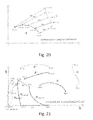
- FIG. 24 illustrates a close-matching 3-tuple
- FIG. 25 illustrates a poorly-matched 3-tuple
- FIG. 26 is an illustration of a triangle-tessellated grid used for analysis in the example embodiment.
- FIG. 27 illustrates a latent print overlaid onto a reference print.
- Embodiments of the invention may be implemented in hardware, firmware, software, or any combination thereof, or may be implemented without automated computing equipment. Embodiments of the invention may also be implemented as instructions stored on a machine-readable medium, which may be read and executed by one or more processors.
- a machine-readable medium may include any mechanism for storing or transmitting information in a form readable by a machine (e.g. a computing device).
- a machine-readable medium may include read only memory (ROM); random access memory (RAM); hardware memory in handheld computers, PDAs, mobile telephones, and other portable devices; magnetic disk storage media; optical storage media; thumb drives and other flash memory devices; electrical, optical, acoustical, or other forms of propagated signals (e.g.
- firmware, software, routines, instructions may be described herein as performing certain actions. However, it should be appreciated that such descriptions are merely for convenience and that such actions in fact result from computing devices, processors, controllers or other devices executing the firmware, software, routines, instructions, etc.
- the term “identification” is sometimes used to mean a process where an individual identity is determined by a one-to-many database search.
- the term “verification” is sometimes used to refer to a process of one-to-one matching.
- each of the terms “identification” and “verification” are intended to encompass both possibilities.
- identity when used, it should be understood that this term may refer to identification and/or verification, and when the term “verification” is used, it should be understood that identification may be included within the scope of verification.
- Advantages of certain embodiments of the novel methods and processes described herein include, among other things, the ability to extract identity information from prints typically classified as having “no identification value” because of sparse or missing minutiae by capturing ridge information, the ability to fuse several individual latent print remnants into a single descriptor of identity, and the ability to render poor quality tenprints useable for reference purposes.
- FIG. 1 a shows examples of latent fingerprint remnants from the same thumb.
- FIG. 1 b is a complete fingerprint image of the subject thumb.
- minutiae-based methods it is impossible to match the latent print remnants of FIG. 1 a against the image stored from a tenprint in FIG. 1 b .
- the inventor has discovered that these latent prints become valuable sources of identity when a ridge-centric identification method is applied.
- FIG. 3 a shows a fingerprint from a tenprint with over-inked zones that have no useful information. The remainder of the print, however, can provide a basis for identification in the context of the current invention.
- the image in FIG. 3 b shows masking applied to the portions of the print that are over-inked and thus invalid for identification purposes.
- Bezier curves are a method of representing geometric paths, named after Pierre Bezier, a French mathematician and engineer who developed this method of drawing in the late 1960s while working for the automobile manufacturer Renault.
- Bezier curves are the cornerstone of Computer Aided Design methods used for architectural and engineering design as well for scalable fonts used in desktop publishing.
- the most basic Bezier curve consists of two end points and two control points.
- FIG. 4 shows a simple Bezier curve and its four related points. Manipulating these defining points can alter the curve.
- Bezier values offer a way of describing curves that is both compact and accurate.
- the four “Bezier points” (two end points and two control points”) replace the entire set of Cartesian plot points that would otherwise be necessary for curve representation.
- FIG. 4 also shows the Bezier-based polygon (quadrilateral) associated with the Bezier curve.
- the angles and distances define a unique representation of the polygon. This, the polygon becomes a unique marker for a particular curve segment. As will be seen, in disclosed embodiments the Bezier curves are applied to provide a means of imputing “minutiae” where traditional minutiae do not exist.
- DSP digital signal processor
- ASIC application specific integrated circuit
- FPGA field programmable gate array
- a general-purpose processor can be a microprocessor, but in the alternative, the processor can be any processor, controller, microcontroller, or state machine.
- a processor can also be implemented as a combination of computing devices, for example, a combination of a DSP and a microprocessor, a plurality of microprocessors, one or more microprocessors in conjunction with a DSP core, or any other such configuration.
- a software module can reside in RAM memory, flash memory, ROM memory, EPROM memory, EEPROM memory, registers, hard disk, a removable disk, a CD-ROM, or any other form of machine or computer readable storage medium.
- An exemplary storage medium can be coupled to the processor such that the processor can read information from, and write information to, the storage medium. In the alternative, the storage medium can be integral to the processor.
- the processor and the storage medium can reside in an ASIC.
- FIG. 5 is a block schematic diagram of an example embodiment of a computing system on which the disclosed analysis can be performed.
- the example embodiment shows a general-purpose computer system 700 , such as a PC system.
- the methods disclosed herein can be performed manually, implemented in hardware, or implemented as a combination of software and hardware. Consequently, desired features of the invention may be implemented in the environment of a computer system or other processing system.
- the computer system 700 includes one or more processors, such as processor 704 .
- Processor 704 can be a special purpose or a general-purpose digital signal processor.
- the processor 704 is connected to a communication infrastructure 706 (for example, a bus or network).
- a communication infrastructure 706 for example, a bus or network.
- Computer system 700 also includes a main memory 705 , preferably random access memory (RAM), and may also include a secondary memory 710 .
- the secondary memory 710 may include, for example, a hard disk drive 712 , and/or a RAID array 716 , and/or a removable storage drive 714 , representing a floppy disk drive, a magnetic tape drive, an optical disk drive, solid state memory, USB port for a thumb drive, PC card slot, SD card slot for a flash memory, etc.
- the removable storage drive 714 reads from and/or writes to a removable storage unit 718 in a well-known manner.
- Removable storage unit 718 represents a floppy disk, magnetic tape, magnetic drive, optical disk, thumb drive, flash memory device, etc.
- the removable storage unit 718 includes a computer usable storage medium having stored therein computer software and/or data.
- Computer system 700 may also include a communications interface 724 .
- Communications interface 724 allows software and data to be transferred between computer system 700 and external devices.
- Examples of communications interface 724 may include a modem, a network interface (such as an Ethernet interface), a communications port, a wireless network communications device such as an IEEE 802.11x wireless Ethernet device, 3G or 4G cellular data connection, a PCMCIA slot and card, etc.
- Software and data transferred via communications interface 724 are in the form of signals 728 which may be electronic, electromagnetic, optical or other signals capable of being received by communications interface 724 . These signals 728 are provided to communications interface 724 via a communications path 726 .
- Communications path 726 carries signals 728 and may be implemented using wire or cable, fiber optics, a phone line, a cellular phone link, an RF link and other present or future available communications channels.
- computer program medium and “computer usable medium” are used herein to generally refer to all available types of digital media, for example, removable storage drive 714 , a hard disk installed in hard disk drive 712 , and signals 728 . These computer program products are means for providing software to computer system 700 .
- Computer programs are stored in main memory 708 and/or secondary memory 710 . Computer programs may also be received via communications interface 724 . Such computer programs, when executed by the processor 704 , enable the computer system 700 to implement the present invention as discussed herein. In particular, the computer programs, when executed, enable the processor 704 to implement the processes of the present invention. Where the invention is implemented using software, the software may be provided as a computer program product on media or transmitted digitally via one of the network connections available to computer system 700 , and loaded into computer system 700 , for example on raid array 716 , removable storage drive 714 , hard drive 712 or communications interface 724 .
- Bezier polygons define unique features in places where bifurcations and terminations either do not exist or are sparse.
- the Ridge Specific Markers create “anchor points” from which graph-based recognition processes can be applied to fingerprints.
- the Bezier polygons serve as a building block for graphs.
- the centroids of the polygons become the “vertices” of the graph.
- the “edges” for these graphs take the form both of actual ridgelines as well as connectors between the Ridge Specific Markers.
- graphs are built from multiple combinations of Ridge Specific Markers.
- FIG. 8 a shows an example of a graph with a single polygon
- FIG. 8 b shows an example with paired polygons
- FIG. 8 c shows an example with triplet polygons.
- An example embodiment presented herein uses a pair-wise graph as a comparative structure, however, those skilled in the art will understand that any number of polygons can be selected within the scope of the invention.
- the number of polygons used to build the graph may be any desired number determined through experimentation, and may be larger than two or three.
- specific comparisons can be made between specific ridges either through direct comparison or through comparison of polygon representations and these comparisons in their own right provide significant identification power
- graphs can be used to describe the overall relationships among the ridges to further expand this identification power.
- FIG. 9 a shows a latent print from the same thumb that produced the full reference print shown in FIG. 9 b .
- a Ridge Specific Marker process is applied to identify common ridges between the same prints.
- latent print identification is performed through a multiple step process that ingests images of latent prints and produces a ranked list of identities.
- the ranking in this list reflects the strength of the match between the latent print and the corresponding reference.
- “reference prints” may refer either to tenprints, partial sets of reference prints, or other latent prints.
- FIGS. 11 a and 11 b together comprise a flow chart showing one example embodiment of a method for processing individual latent prints and comparing them against a collection of references.
- the fingerprint image is converted into a high-contrast representation of ridge flow.
- Step 1102 is preferably performed according to the process shown in the flow chart of FIG. 12 .
- a fingerprint pattern may be idealized as a wavelike pattern of periodic ridges. That is, over a limited region of the image, the pattern may be expressed as a sinusoidal wave function, plus some offset value.
- the wave frequency and amplitude, as well as the offset value are constant over a limited region of the image, though they are likely to vary from one region of the image to another. It is not expected that the image brightness will actually follow a sinusoidal function; the point is that representation of the pattern by such a function captures the essential feature of the pattern, viz, the positions of lines of maximum and minimum intensity.
- marking is done with dark ink on a lighter background; the lines of intensity minimum therefore correspond to the axes of the ridges, while the maxima correspond to the axes of the valleys between the ridges.
- the processing method rather than representing the print as a wave pattern, the processing method generates a normalized representation in which the points on the ridge axes have the value ⁇ 1, the points on the inter-ridge axes have the value +1, and intermediate points have intermediate values. The result is a clear uniform image of the ridges.
- Real fingerprint images are subject to a number of corrupting influences that cause the image to differ from a simple periodic ridge pattern. These include: image noise introduced by the image capture process itself, variations in thickness of the ink or other marking medium causing the darkness of the ridges to be non-uniform, variation in the brightness of the background, and irregularity in the ridges themselves including wiggles and transient features such as spurs and breaks. Strictly speaking, these are not noise, inasmuch as they reflect what is actually present on the fingertip. However, they are extraneous to the ridge pattern so it is desirable to eliminate these irregularities during image processing.
- the processing comprises reducing or eliminating these various kinds of noise, then normalizing the result so that the image values range from ⁇ 1 (ridge axes) to +1 (valley axes).
- segmentation of the print refers to separation of the image into foreground (print) and background, each point in the image being assigned to one or the other.
- the foreground is defined as the part of the image in which the ridge pattern can be retrieved.
- a point may be labeled as background for one of two reasons; it may be outside the area contacted by the fingertip, or it may be within the area, but the ridge pattern may be too unclear to delineate it with confidence.
- Foreground and background points are labeled with the values 1 and 0 respectively.
- step 1202 the process of converting an image into a high-contrast representation of ridge flow begins with step 1202 , where the image is read into memory from the user-specified file. If it is not a grayscale image, it is preferably converted to a grayscale data format.
- step 1206 the orientation pattern of the ridges is analyzed.
- This step retrieves a number of quantities, including the orientation of the ridge pattern at each point.
- Another quantity determined in the example embodiment is coherence.
- Coherence is represented by a number between 0 and 1, and is a measure of how well defined the orientation pattern is at each point.
- a value of 1 corresponds to the optimum situation, where all the intensity variation in the image is in one direction (perpendicular to the ridges), with no variation in the direction parallel to the ridges, A value of 0 indicates no preference for one direction over another, as would occur in a region of uniform brightness or with random image noise that was not directionally dependent.
- the ridge orientation field is obtained by a method that will be referred to as Principal Component Analysis. This process identifies the direction at each point in the image in which the intensity variation per unit is greatest; in a ridge pattern this is typically perpendicular to the ridges. Because the intensity gradient along any direction, which is the measure of the variation, may be positive or negative, the square of the intensity gradient is used. In particular, at each point the direction is identified for which the squared intensity gradient, taken along this direction and averaged over the neighborhood of the point, is a maximum.
- the energy E is a measure of the total image variation without reference to direction, while ft, the directional response, measures the total directionally dependent image variation.
- R is zero when the pattern is completely isotropic, i.e. when the average amount of variation is the same no matter which direction one moves within the image; it is equal to E when all the variation is along one direction, as for example in the case of a set of perfectly parallel lines.
- the quantity C R/E therefore always lies between 0 and 1, and may be used as a measure of the pattern's coherence, or how well the orientation of the pattern is defined. Very low coherence values occur in areas where the fingerprint is smudged or otherwise corrupted, as well as in most parts of the background; C is therefore one quantity that is useful in separating the print foreground from the background.
- the quantities obtained in this analysis stage are used in the later noise removal stages, and they also provide important cues when performing segmentation.
- segmentation is performed by applying a series of segmentation masks.
- a segmentation mask is an image consisting of a set of binary values for all points in the image. Points assigned a value of 1 are denoted “foreground”; points assigned a value of zero are denoted “background”.
- three different segmentation masks are generated, based on three different quantities.
- a coherence segmentation is generated by assigning a value of 1 to all points where the quantity C, defined above, is greater than a threshold value.
- the threshold may be selected by experimentation to correspond to characteristics of the image.
- a value of 0.3 is typical of a coherence value at which the ridge orientation is readily discernible.
- this mask is modified to fill in holes occurring at a singularity in the flow pattern (a core or delta point). At these points, the coherence drops to a very low value. This is not because the ridges are poorly defined at this point, but because the orientation varies rapidly over a small region of space. This leaves “holes” in the mask at these points, the size of the hole being roughly equal to the radius of the neighborhood used in taking the means of gradient quantities to calculate D and P above. This operation is referred to as morphological closure.
- the coherence segmentation is normally effective in including all the fingerprint regions where the pattern can be interpreted with the human eye, and it masks out most of the background.
- certain types of background features that show high directional coherence, such as handwritten annotations, ruled lines on the card or the grain of the surface on which the print was made.
- the coherence mask is supplemented by additional masks.
- a second mask based on directional response is generated based on the quantity R defined above.
- This quantity is a magnitude rather than a dimensionless quantity such as coherence; it measures the amount (in intensity per pixel displacement) by which the intensity varies in a directionally dependent manner.
- This mask eliminates background regions where the pattern is faint but highly linear. Many materials such as paper or wood exhibit a grain structure that is normally much fainter than the fingerprint ridges and may even not be discernible to the eye in the original image. This grain structure will result in high values for coherence, so that a coherence mask alone will erroneously include these areas as part of the foreground.
- R m is found, such that only 5% of the points in the image have a value R>R m . If the foregoing assumption is valid, then this means that R m will be a value representative of points within the print foreground. Some foreground points will have a greater value of R; most will show a smaller value.
- the threshold value R T is then set to 0.01*R m . This allows the mask to include regions where R is significantly less than the 95-percentile value. However it successfully masks out regions described above, namely parts of the background where there is a linear pattern corresponding to a very faint grain.
- a third mask is generated based on the ridge frequency extracted from the pattern.
- a binary version of the enhanced image is generated by replacing all positive image values by 1 (white) and all negative values by 0 (black). Since the enhanced image is normalized, the values are symmetrical about zero, so the resulting binary image contains roughly the same number of on and off bits. Then, the borders of the black and white regions are identified. These are pixels whose binary value differs from the binary value of one or more of its neighbors.
- the ridge frequency is half this value.
- the frequency mask shows holes similar to those in the coherence segmentation mask, and for the same reason; the core and delta points are points at which the orientation is ill-defined, therefore the frequency, measured along a particular direction, is also not well-defined. These holes are filled in using the same procedure as in the coherence mask.
- the frequency-based segmentation filters out parts of the back-ground containing features such as ruled lines or handwritten notes.
- Such patterns are highly linear, but they are typically isolated lines rather than a series of parallel lines such as is found in the ridge pattern.
- the three segmentation masks described above are preferably combined into one final segmentation mask by an intersection operation. That is, a point is marked as foreground in the final mask if and only if it is a foreground point in all three individual masks.
- the example embodiment deals with two complications arising in the case of ridge orientation patterns. The first is that orientation is an ambiguous quantity, as noted above. An orientation of 30° is indistinguishable from an orientation of 150°. The example embodiment compensates for this factor by doubling the angle, then smoothing the doubled angle (which we denote ⁇ ) by means of a weighted averaging, and finally halving the result.
- a core point is characterized by the fact that, if a closed path is traced around the point and follow the behaviour of the orientation, this vector rotates by 180 degrees for a single clockwise traversal of the closed path.
- the doubled angle therefore rotates by 360 degrees.
- the same behavior happens at a delta point, except that the rotation is in the opposite sense.
- the cores and deltas can be treated as generating spirals in the orientation field, the spiral flows being superimposed on an otherwise continuous flow pattern.
- the spiral field from a core point P is the bearing angle from the point (x,y) to the point P. This has the desired property that when any closed path is traced around P, the angle does one complete rotation.
- Core and delta points in the original ⁇ field are located in the example embodiment using a quantity called the Poincaré index. This is obtained using the spatial derivatives of the angle (in mathematical language, it is the curl of the x and y spatial derivatives of the angle), and its value is 2 ⁇ at a core point, ⁇ 2 ⁇ at a delta, and zero everywhere else.
- ridge enhancement is performed.
- the ridge enhancement process is an image smoothing operation that smoothes intensity variations in the direction parallel to the ridges, while those in the perpendicular direction are largely unaffected.
- the example embodiment seeks to avoid smoothing in the cross-ridge direction, since this would eventually destroy the pattern of ridges and valleys, which are features of interest to be enhanced rather than diminished.
- Ridge enhancement is a process for reducing or eliminating irregularities in the ridge pattern, making it conform more closely to a theoretically ideal ridge pattern. Ideally the pattern resembles a wave pattern with no breaks in the waves, with the crests and trough having the same amplitude everywhere. In this idealized ridge pattern the intensity is constant when one traces a path in the image parallel to the ridges.
- noise consisting of small intensity fluctuations in an image is reduced or eliminated by applying a suitably chosen smoothing filter, which replaces the intensity value at a pixel by a value calculated as a weighted average of pixels in a restricted neighborhood.
- a modified process is desirable to ensure that any smoothing takes place only in the direction parallel to the ridges, otherwise spatial averaging may reduce or eliminate the ridges themselves.
- oriented diffusion is performed as follows: (1) Obtain the second spatial derivative f′′ of intensity, taken at each pixel in the direction of the ridge orientation; (2) Average this quantity over a very small neighborhood of the pixel (the size of the neighborhood used is somewhat less than the average ridge wavelength); (3) Apply the above formula to estimate the mean intensity; and (4) Repeat the above steps as often as desired.
- a quadrature operation is applied to the image, allowing the intensity at each point to be expressed in terms of the amplitude and phase of a sine wave.
- the quadrature operation follows the processes disclosed by Larkin and Fletcher for obtaining the quadrature of a two-dimensional image function.
- the original function, together with its quadrature, may be combined to produce a complex valued function representing a periodic wave, and the phase at any point can be obtained by examining the relative values of the real and imaginary parts of the complex function.
- Obtaining the quadrature requires specifying the direction of the wave normal at each point. This is at right angles to the ridges, but as noted above, it is only possible to specify the ridge orientation as being in one of two directions, 180 degrees apart. This ambiguity in the wave direction results in a corresponding ambiguity in the phase. However, the quantity of primary interest in the height of the wave at each point, measured by the cosine of the phase. The same cosine value is found irrespective of which of the two possible directions was taken as the wave normal.
- step 1216 if applicable, the resultant smoothed and normalized image and the foreground mask image are each written to user-specified storage locations.
- Skeletonizing the high contrast image creates a version of the image in which the ridges are represented as pathways one pixel in width and equidistant to the original contours of the ridge.
- the skeleton image preserves the geometrical and topological properties of the ridges, such as connectivity, topology, length, direction, and width. Together with the distance from the skeleton points to corresponding ridge contour points, the skeleton contains all the information necessary to reconstruct the shapes of the ridges as shown in the high contrast image.
- the high contrast image is preferably thresholded to black and white. Because it is already in high contrast form, a single threshold value can be used and all pixel values above the threshold convert to white and all pixel values below (or equal to) the threshold convert to black.
- FIG. 15 b shows a skeleton portion taken from within the fingerprint image shown in FIG. 15 a.
- the first step in Bezier curve generation is to segment the ridges into sections. This is accomplished by establishing rules for segmentation.
- each curve should have a length of 260 units and curves should be generated every interval of 60 units, where a “unit” represents 1/1000 of an inch which is a common resolution for fingerprint images.
- FIG. 16 shows an example of curve selection from a single ridge with staggered starting points and overlap for each identified curve. In this figure, the furrows are shown in light gray and the ridges are white. The wide black segment superimposed on the ridges represents a Bezier curve segment.
- FIG. 16 illustrates three such segments representing the “staggering” of starting point selection. In this example embodiment the starting points are spaced by 60 units. If a single ridge is not as long as the starting point spacing (60 units in the example embodiment), the entire length of the ridge is used as a single segment.
- ( n k ) is a binomial coefficient.
- the Bernstein polynomials of degree n form a basis for the power polynomials of degree n.
- each basis vector has m values.
- regression vectors are constructed using the (x, y) values given by the edge points. Scale all (x, y) values so that x has the endpoints at interval [0, 1] and y has the endpoints at interval [0, 1], where
- u 1 v 1
- e k u k ⁇ u k ⁇
- this method proceeds as follows: to compute u i , it projects v i orthogonally onto the subspace U generated by u 1 , . . . , u i-1 , which is the same as the subspace generated by v 1 , . . . , v i-1 .
- the vector u i is then defined to be the difference between v i and this projection, guaranteed to be orthogonal to all of the vectors in the subspace U.
- the process is setup as a matric with the following structure:
- the form of the coefficients in the lower right corner of the matrix is preferably modified during the process.
- Each column pair, where the 0 matrix was originally, contains the (x, y) coefficient information, but shifted and negative.
- Each (x′, y′) pairing is transformed using the xShift and yShift values from above.
- the coefficients are preferably read in order.
- a given threshold for example, 10
- the result is a distribution of Bezier curves across the latent print where longer ridges are represented mostly by longer Bezier curves and shorter ridges are sampled with a variety of Bezier curves of shorter lengths and intervals.
- RSim Bezier (A,B), the relative similarity between two Beziers, is defined in the following manner (illustrated in FIG. 19 ).
- the best relative geometric fitting Beziers are the Bezier curves that scored the lowest by this metric.
- the two Bezier curves are aligned along an x-axis such that each of the Beziers' starting points lie at the origin, and their ending points lie on the x-axis in the positive direction.
- RSim Tuple (T,T′) the relative similarity between two 3-tuple Bezier curve sets, T(A,B,C) T(A′,B′,C′) is defined as sqrt(RSim Bezier (A,A′) 2 +RSim Bezier (B,B′) 2 +RSim Bezier (C,C′) 2 +PosSim(AB,A′B′) 2 +PosSim(BC,B′C′) 2 +PosSim(CA,C′A′) 2 , where PosSim(AB,A′B′) is the positional similarity between the Bezier pairs AB and A′B′, and is defined as follows (illustrated in FIG. 21 ). The best relative geometric fitting 3-tuple is the 3-tuple that has the lowest score under this metric.
- PosSim(AB,A′B′) sqrt(sigma(n,1,4) ⁇ (Dist(PAligned AB [n], PAligned A′B′ [n]) 2 ) ⁇ ), where Dist is the geometric distance function and sqrt is the square root function ( FIG. 21 ).
- a 3-tuple Bezier match is found in the reference for each Bezier RefB start defined by the combination f: (LatB N ,C N,M ,RefB O ) ⁇ RefB start
- FIG. 25 shows a poor matching 3-tuple based on a RefB start defined by a different C N,M .
- step 1114 the overall estimated rotational difference between orientation of the latent print and the reference print, ⁇ est , is determined.
- T L latent 3-tuple
- T R reference 3-tuple
- the angle difference between their orientations is found as follows.
- Ang(AB,A′B′) the angle difference between two Bezier pairs, AB, and A′B′, is Ang(AB) ⁇ Ang(A′B′).
- Ang 3-tuple (T,T′) the angle difference between the orientations of two 3-tuples, T consisting of 3 Bezier curves, ABC (T(ABC)), and T′(A′B′C′), is equal to the angle average of Ang(AB,A′B′), Ang(BC,B′C′), and Ang(CA,C′A′).
- the “angle average” of a set of angle measurements consists of shifting all of the values by some degree, ⁇ , that minimizes the sum of the absolute values of the differences between all pairs of shifted angles. The “shifted average” is then taken from these values, and this “shifted average” is shifted back ⁇ degrees to become the final average of the angles.
- the estimated rotational difference between orientation of the latent print and the reference print, ⁇ est is the angle average of R(x).
- the Bezier 3-tuple sets from the latent are re-extracted as per the instructions in step 1110 , but a specifiable maximum distance is also set between the centroids of the Beziers involved in a 3-tuple set when the extraction is being done.
- the maximum distance for this calculation is 200 pixels.
- step 1118 two vectors of points (of equal magnitude) are selected, one for the latent fingerprint, V L , and one for the reference print, V R , that will serve as control points between “latent fingerprint space” and “reference fingerprint space” in order to create a transformation between the two spaces.
- This process begins with the empty vectors of points, V L and V R .
- the set of 3-tuples found in step 1112 ) that includes B Latent is found.
- the Bezier, B Reference in the best matching reference 3-tuple (found in step 1116 ) that corresponds to B Latent is identified.
- B reference is added to the set S of reference Bezier curves that match B Latent .
- step 1120 the control point vectors, V L and V R , are used to create a transformation between latent and reference space.
- the first control point in V L , V L [0], is “mapped” to V R [0]
- V L [1] is mapped to V R [1], and so on.
- the function f: P x ,P y ,T X1 ,T Y1 ,T X2 ,T Y2 ,S 1 ,S 2 ,A ⁇ P x ′,P y ′, is a function that takes a arbitrary point, P, and a set of constants, T X1 ,T Y1 ,T X2 ,T Y2 ,S 1 ,S 2 ,A, and returns a transformed point, P′.
- V,V′ ⁇ T X1 ,T Y1 ,T X2 ,T Y2 ,S 1 ,S 2 ,A is a function that generates the constants for f given two vectors of points, V, V′, with equal magnitudes (Note: V n .X denotes the X coordinate of the nth member of V, and V n .Y denotes the Y coordinate).
- g(V,V′) ⁇ T X1 ,T Y1 ,T X2 ,T Y2 ,S 1 ,S 2 ,A
- T X1 sigma(n,1,N) ⁇ V n .X/N ⁇
- T Y1 sigma(n,1,N) ⁇ V n .Y/N ⁇
- T X2 sigma(n,1,N) ⁇ V′ n .X/N ⁇
- T Y2 sigma(n,1,N) ⁇ V′ n .Y/N ⁇
- S 1 Sqrt(sigma(n,1,N) ⁇ ((V n .X ⁇ T X1 ) 2 +(V n .Y ⁇ T Y1 ) 2 )/N ⁇ )
- S 2 Sqrt(sigma(n,1,N) ⁇ ((V′ n .X ⁇ T X2 ) 2 +(V′ n .Y ⁇ T Y2 ) 2
- the latent fingerprint space is split into a triangle-based tessellated grid as depicted in FIG. 26 (the per-cell width being a specifiable number, which in the example embodiment is set at 200 pixels).
- a transformation f: P x ,P y ,T X1 ,T Y1 ,T X2 ,T Y2 ,S 1 ,S 2 ,A ⁇ P x ′,P y ′ is defined for each vertex or distortion-point, Dp, on the grid.
- V Dp ,V′ Dp ⁇ T X1 ,T Y1 ,T X2 ,T Y2 ,S 1 ,S 2 ,A where V Dp is a subset of V Reference and V′ Dp is a subset of V Latent .
- V′ Dp is determined by taking the set of points within V Latent in the ring of square, tessalated grid cells neighboring Dp. If a specifiable minimum number of points in V Latent are not found (in this case, 5), then the points in the next ring of square, tessellated grid cells are included. This pattern continues until the minimum is met.
- an affine transformation matrix, M can be defined for that triangle that will transform any point within that triangle in latent space into reference space. Also, the inverse matrix, M ⁇ 1 , will transform any point lying in the transformed triangle in reference space back to latent space.
- step 1122 the transformation grid is refined using two new control point vectors V RefinedL and V RefinedR .
- Each Bezier curve in the latent print, B L (sampled at length L and interval I) is transformed into reference space via the transformation grid created in step 1120 .
- Each of the physical pixel points of the Bezier curve are transformed into reference space, and a new Bezier, B′ L , is calculated using the processes defined in step 1106 .
- the best absolute geometric fitting Bezier in the reference print to B′ L (B R ) is found out of the set of reference Bezier curves created from sampling length L, at the “fine” interval (in the example embodiment this interval is 5).
- step 1126 for each pairing, five points on each curve in the pairing are identified: two endpoints, two quarter points and one center point.
- FIG. 21 illustrates corresponding curves identified in latent space and reference space.
- step 1128 feature vectors are created for each curve in the pairing set, incorporating the ten values related to the points (five ‘x’ values and five ‘y’ values). These feature vectors are created using the x and y coordinates from the Bezier curve.
- FIG. 21 illustrates a sample curve and data vector that it produces.
- step 1132 processing continues in step 1132 as shown in FIG. 11 b .
- the RMSE values are captured and stored for each Bezier curve in the latent print and each reference print for which there is a match.
- step 1134 steps 1108 through 1132 are repeated for each reference print being considered, to obtain a corresponding data set for each reference print.
- scoring is performed by successively building upon sets of individual Bezier-based triangles and then recombining the points from these triangles into new triangles, until a sufficient number of triangle driven matches are made to distinguish the best reference print matching the latent.
- step 1137 the entire set of Bezier polygons from the latent print is grouped into disjoint sets each containing three Bezier polygons.
- each latent Bezier 3-polygon set referred to as a latent Bezier “triangle,” is compared with a set of Bezier triangles for the reference print, and the Bezier triangle that best maintains the relative relationships between the Bezier polygons in the latent Bezier triangle is identified. This is done for all of the latent Bezier triangles, resulting in a set of matching reference Bezier triangles.
- these matches are filtered to remove the matching reference triangles that have poor measurable similarity to their corresponding latent triangle or are not rotationally consistent with the rest of the matching reference triangles (the set of all reference triangles should be rotated the same amount from their matching latent triangle within some theta if these matches are indeed correct). What is left is a set of Bezier polygons, if any, that are the most confident matches between the latent and the given reference fingerprint.
- step 1143 the points that make up these polygons are used as control points to estimate a transformation from latent to reference coordinate space.
- step 1145 the process of steps 1137 through 1143 is iterated by using these areas of similarity (consisting of confident Bezier matches, if any, between the latent and a reference print) as a new set of control points to generate an improved transformation between latent and reference space. This iterative process is then continued until a local minimum is achieved where the quality of matching between the latent and reference print cannot be significantly improved. An indication of the result is then provided as an output.
- fingerprints can be compared using data sets derived from imaged ridge contours and a latent print can be scored for similarity to a reference print as part of an identification or verification process.
- the scoring method disclosed herein provides basic scoring functionality. In other embodiments, more complex scoring algorithms may be used.
- the preferred example embodiment uses scoring methods disclosed in the same inventors' copending Patent Cooperation Treaty Application, Serial No. PCT/US2012/024034, titled “Systems and Methods for Biometric Identification,” filed Feb. 6, 2012; the entire disclosure of this PCT application is incorporated herein by reference.
- Pre-processing of fingerprint images for comparison and the subsequent comparisons may be performed in a single location, either using a single computing device, or with the software/firmware functions divided among two or more computing devices.
- reference images and latent images may first be analyzed to obtain a Bezier representation of their ridge structures, either at the same or different locations. The comparison may then be performed at either of these image processing locations, or at a third location.
- the process may be divided between an unlimited number of locations and processing devices.
- the digital representations will be electronically transferred to a comparison environment, whereby features represented in said digital representations may be compared with the fingerprint reference data.
- the comparison environment may be the same processor used to create the digital representations, in which case the transfer to the comparison environment may merely constitute the loading of comparison software instructions into the processor. If the comparison environment is a different processor or is at a different location, this transfer may involve conveying electronic information between different computing devices, using storage devices, a local area network, the internet, a private network, or another of the large number of data transfer mechanisms known to those skilled in the art.
Landscapes
- Engineering & Computer Science (AREA)
- Human Computer Interaction (AREA)
- Physics & Mathematics (AREA)
- General Physics & Mathematics (AREA)
- Multimedia (AREA)
- Theoretical Computer Science (AREA)
- Computer Vision & Pattern Recognition (AREA)
- Image Processing (AREA)
- Collating Specific Patterns (AREA)
Abstract
Description
2Θ=arctan(P/D)
where
D=mean(g x 2 −g y 2)
P=mean(2g x g y)
and gx and gy are the image intensity gradients in the x and y directions respectively.
R=√{square root over ((D 2 +P 2))}
E=mean(g x 2 +g y 2)
Φ=ΦC+ΦS
where ΦC is the residual field, and is ΦS the spiral orientation field resulting from the presence of the cores and deltas.
-
- 1. Calculate the doubled angle Φ;
- 2. Locate the core points using the Poincaré index;
- 3. Calculate the spiral field across the image for each core and delta point, and sum these to give ΦS;
- 4. Subtract ΦS from Φ to give ΦC;
- 5. Smooth ΦC using a weighted neighborhood average;
- 6. Add ΦS back to the result to give a final smoothed field Φ with the core and delta points preserved.
f(x 0 +d)=f(x 0)+f′(x 0)d+[f″(x 0)]d 2/2+
where f′(x0), f″(x0) etc are the 1st, 2nd etc. derivatives of fat the point x0.
mean(f)≈f(x 0)+[f″(x 0)]*mean(d 2)/2
The term “mean (d2)” is constant, and simply depends on the size of our chosen interval. The equality is only approximate, because the full Taylor expansion contains higher order terms.
where
is a binomial coefficient. The Bernstein polynomials of degree n form a basis for the power polynomials of degree n. For the algorithm herein described, n=order−1 and i=1, . . . m. Note that each basis vector has m values. Next, regression vectors are constructed using the (x, y) values given by the edge points. Scale all (x, y) values so that x has the endpoints at interval [0, 1] and y has the endpoints at interval [0, 1], where
-
- xShift=x-value at the first edge point.
- xScale=x-value at last edge point x-value at first edge point.
- yShift=y-value at the first edge point.
- yScale=y-value at last edge pointy-value at first edge point.
At each edge point, compute t=j/m, j=0, . . . , m−1. Transform all the x-values by:
x New[j]=x Val[j]−x Scale t n+1 −x shift
y New[j]=y Val[j]−y Scale t n+1 −y Shift
Once the basis and regression vectors all of length m have been created, a Graham-Schmidt orthogonalization routine is used to determine the values of the two missing control points. These values are the best control points possible computed to minimize the error between the Bezier the specified order and the supplied edge points. In an embodiments, the projection operator is defined by
where <v,u> denotes the inner product of the vectors v and u. This operator projects the vector v orthogonally onto the line spanned by vector u. The Gram-Schmidt process then works as follows:

Applying the Graham-Schmidt process to the column vectors of the matrix, provides:
x=−1.0x+xShift
y=−1.0y+yShift
Since this process is being used to create 4 control points, there are 2 coefficient pairings and the identity matrix in the formulation is a 2×2. The coefficients are preferably read in order.
Claims (9)
Priority Applications (1)
| Application Number | Priority Date | Filing Date | Title |
|---|---|---|---|
| US13/367,153 US10445555B2 (en) | 2009-01-27 | 2012-02-06 | Systems and methods for ridge-based fingerprint analysis |
Applications Claiming Priority (4)
| Application Number | Priority Date | Filing Date | Title |
|---|---|---|---|
| US14772009P | 2009-01-27 | 2009-01-27 | |
| US12/611,893 US20100189316A1 (en) | 2009-01-27 | 2009-11-03 | Systems and methods for graph-based pattern recognition technology applied to the automated identification of fingerprints |
| US201161439802P | 2011-02-04 | 2011-02-04 | |
| US13/367,153 US10445555B2 (en) | 2009-01-27 | 2012-02-06 | Systems and methods for ridge-based fingerprint analysis |
Related Parent Applications (1)
| Application Number | Title | Priority Date | Filing Date |
|---|---|---|---|
| US12/611,893 Continuation-In-Part US20100189316A1 (en) | 2009-01-27 | 2009-11-03 | Systems and methods for graph-based pattern recognition technology applied to the automated identification of fingerprints |
Publications (2)
| Publication Number | Publication Date |
|---|---|
| US20130101186A1 US20130101186A1 (en) | 2013-04-25 |
| US10445555B2 true US10445555B2 (en) | 2019-10-15 |
Family
ID=48136026
Family Applications (1)
| Application Number | Title | Priority Date | Filing Date |
|---|---|---|---|
| US13/367,153 Active 2030-01-05 US10445555B2 (en) | 2009-01-27 | 2012-02-06 | Systems and methods for ridge-based fingerprint analysis |
Country Status (1)
| Country | Link |
|---|---|
| US (1) | US10445555B2 (en) |
Cited By (1)
| Publication number | Priority date | Publication date | Assignee | Title |
|---|---|---|---|---|
| US11783453B2 (en) | 2021-06-10 | 2023-10-10 | Bank Of America Corporation | Adapting image noise removal model based on device capabilities |
Families Citing this family (24)
| Publication number | Priority date | Publication date | Assignee | Title |
|---|---|---|---|---|
| ATE477548T1 (en) | 2006-04-26 | 2010-08-15 | Aware Inc | QUALITY AND SEGMENTATION OF A FINGERPRINT PREVIEW |
| US9342725B2 (en) | 2012-06-29 | 2016-05-17 | Apple Inc. | Image manipulation utilizing edge detection and stitching for fingerprint recognition |
| US9092652B2 (en) * | 2012-06-29 | 2015-07-28 | Apple Inc. | Zero reference based ridge flow map |
| US9035895B2 (en) | 2012-07-13 | 2015-05-19 | Apple Inc. | Redundant sensing element sampling |
| US9218544B2 (en) | 2013-02-01 | 2015-12-22 | Apple Inc. | Intelligent matcher based on situational or spatial orientation |
| US9727773B2 (en) * | 2013-08-21 | 2017-08-08 | Nec Corporation | Fingerprint core extraction device for fingerprint matching, fingerprint matching system, fingerprint core extraction method, and program therefor |
| US9436863B2 (en) | 2013-09-09 | 2016-09-06 | Apple Inc. | Reconstructing a biometric image |
| AU2013245477A1 (en) * | 2013-10-16 | 2015-04-30 | Canon Kabushiki Kaisha | Method, system and apparatus for determining a contour segment for an object in an image captured by a camera |
| CN104751112B (en) * | 2013-12-31 | 2018-05-04 | 石丰 | A kind of fingerprint template and fingerprint identification method based on fuzzy characteristics point information |
| FR3017230B1 (en) * | 2014-02-04 | 2016-03-11 | Morpho | METHOD FOR VALIDATING THE USE OF A TRUE FINGER AS A SUPPORT OF A DIGITAL FOOTPRINT |
| EP3195197B1 (en) * | 2014-09-18 | 2024-11-06 | Sciometrics, LLC | Noise reduction for fingerprint images captured by a mobile device |
| WO2016105558A1 (en) * | 2014-12-24 | 2016-06-30 | Sciometrics Llc | Unobtrusive identity matcher: a tool for real-time verification of identity |
| US10339362B2 (en) | 2016-12-08 | 2019-07-02 | Veridium Ip Limited | Systems and methods for performing fingerprint based user authentication using imagery captured using mobile devices |
| US11263432B2 (en) | 2015-02-06 | 2022-03-01 | Veridium Ip Limited | Systems and methods for performing fingerprint based user authentication using imagery captured using mobile devices |
| US9424458B1 (en) | 2015-02-06 | 2016-08-23 | Hoyos Labs Ip Ltd. | Systems and methods for performing fingerprint based user authentication using imagery captured using mobile devices |
| KR102338864B1 (en) | 2015-02-12 | 2021-12-13 | 삼성전자주식회사 | Electronic device and method for registration finger print |
| US9972106B2 (en) * | 2015-04-30 | 2018-05-15 | TigerIT Americas, LLC | Systems, methods and devices for tamper proofing documents and embedding data in a biometric identifier |
| US9741133B2 (en) * | 2015-09-29 | 2017-08-22 | Adobe Systems Incorporated | Identifying shapes in an image by comparing Bézier curves |
| EP3185206B1 (en) * | 2015-12-22 | 2018-09-26 | Thomson Licensing | Methods and systems for image processing of digital images |
| SE1650416A1 (en) * | 2016-03-31 | 2017-10-01 | Fingerprint Cards Ab | Secure storage of fingerprint related elements |
| KR102561723B1 (en) * | 2016-12-08 | 2023-07-31 | 베라디움 아이피 리미티드 | System and method for performing fingerprint-based user authentication using images captured using a mobile device |
| SE1750155A1 (en) * | 2017-02-17 | 2018-08-18 | Fingerprint Cards Ab | Enabling identification of fingerprints from captured imagesusing contour points |
| US20190155917A1 (en) * | 2017-11-17 | 2019-05-23 | Daniel Felipe Lopez Zuluaga | Image-based deduplication process for digital content |
| JP7420278B2 (en) * | 2020-09-29 | 2024-01-23 | 日本電気株式会社 | Information processing device, information processing method, and recording medium |
Citations (7)
| Publication number | Priority date | Publication date | Assignee | Title |
|---|---|---|---|---|
| US20010016055A1 (en) * | 1997-04-11 | 2001-08-23 | Curt R. Harkless | "systems & methods with identity verification by streamlined comparison & interpretation of fingerprints and the like" |
| US20020126883A1 (en) * | 1998-01-07 | 2002-09-12 | Andrew W. Senior | System and method for transforming fingerprints to improve recognition |
| US20020168093A1 (en) * | 2001-04-24 | 2002-11-14 | Lockheed Martin Corporation | Fingerprint matching system with ARG-based prescreener |
| US20030091724A1 (en) * | 2001-01-29 | 2003-05-15 | Nec Corporation | Fingerprint identification system |
| US20040101173A1 (en) * | 2002-08-13 | 2004-05-27 | Nec Corporation | Method and apparatus for analyzing streaked pattern image |
| US20080101663A1 (en) * | 2006-10-31 | 2008-05-01 | Motorola, Inc. | Methods for gray-level ridge feature extraction and associated print matching |
| US20080192988A1 (en) * | 2006-07-19 | 2008-08-14 | Lumidigm, Inc. | Multibiometric multispectral imager |
-
2012
- 2012-02-06 US US13/367,153 patent/US10445555B2/en active Active
Patent Citations (7)
| Publication number | Priority date | Publication date | Assignee | Title |
|---|---|---|---|---|
| US20010016055A1 (en) * | 1997-04-11 | 2001-08-23 | Curt R. Harkless | "systems & methods with identity verification by streamlined comparison & interpretation of fingerprints and the like" |
| US20020126883A1 (en) * | 1998-01-07 | 2002-09-12 | Andrew W. Senior | System and method for transforming fingerprints to improve recognition |
| US20030091724A1 (en) * | 2001-01-29 | 2003-05-15 | Nec Corporation | Fingerprint identification system |
| US20020168093A1 (en) * | 2001-04-24 | 2002-11-14 | Lockheed Martin Corporation | Fingerprint matching system with ARG-based prescreener |
| US20040101173A1 (en) * | 2002-08-13 | 2004-05-27 | Nec Corporation | Method and apparatus for analyzing streaked pattern image |
| US20080192988A1 (en) * | 2006-07-19 | 2008-08-14 | Lumidigm, Inc. | Multibiometric multispectral imager |
| US20080101663A1 (en) * | 2006-10-31 | 2008-05-01 | Motorola, Inc. | Methods for gray-level ridge feature extraction and associated print matching |
Non-Patent Citations (4)
| Title |
|---|
| Huaqiang, Yuan, et al. "A fingerprint feature extraction algorithm based on curvature of Bezier curve." Progress in Natural Science 17.11 (2007): 1376-1381.6 pages (Year: 2007). * |
| Isenor, D. K., and Safwat G. Zaky. "Fingerprint identification using graph matching." Pattern Recognition 19.2 (1986): 113-122. 10 pages (Year: 1986). * |
| Larkin, Kieran G., and Peter A. Fletcher. "A coherent framework for fingerprint analysis: are fingerprints holograms?." Optics Express 15.14 (2007): 8667-8677. 11 pages (Year: 2007). * |
| Rowe, Robert K., et al. "A multispectral whole-hand biometric authentication system." Biometrics Symposium, 2007. IEEE, 2007. 6 pages (Year: 2007). * |
Cited By (1)
| Publication number | Priority date | Publication date | Assignee | Title |
|---|---|---|---|---|
| US11783453B2 (en) | 2021-06-10 | 2023-10-10 | Bank Of America Corporation | Adapting image noise removal model based on device capabilities |
Also Published As
| Publication number | Publication date |
|---|---|
| US20130101186A1 (en) | 2013-04-25 |
Similar Documents
| Publication | Publication Date | Title |
|---|---|---|
| US10445555B2 (en) | Systems and methods for ridge-based fingerprint analysis | |
| US10552661B2 (en) | Systems and methods for biometric identification | |
| CN101609499B (en) | Rapid fingerprint identification method | |
| CN101777128B (en) | Fingerprint minutiae matching method syncretized to global information and system thereof | |
| US7970186B2 (en) | System, method and computer program product for fingerprint verification | |
| US11017210B2 (en) | Image processing apparatus and method | |
| CN112287872B (en) | Iris image segmentation, positioning and normalization method based on multitask neural network | |
| US8666170B2 (en) | Computer system and method of matching for images and graphs | |
| EP1229488A2 (en) | Information processing method and apparatus | |
| Zhang et al. | A multi feature fusion method for reassembly of 3D cultural heritage artifacts | |
| CN106716442B (en) | Fingerprint authentication system, fingerprint authentication program, and fingerprint authentication method | |
| CN113011426A (en) | Method and device for identifying certificate | |
| JP7251670B2 (en) | Feature quantity generation device, system, feature quantity generation method and program | |
| CN101770566A (en) | Quick three-dimensional human ear identification method | |
| Cui et al. | Dense registration and mosaicking of fingerprints by training an end-to-end network | |
| CN108022245A (en) | Photovoltaic panel template automatic generation method based on upper thread primitive correlation model | |
| CN107958208A (en) | A kind of fingerprint crossing storehouse matching method based on propagation algorithm | |
| EP0460960A2 (en) | Data processing | |
| CN101840513A (en) | Method for extracting image shape characteristics | |
| CN100447806C (en) | Method, device and use for matching two-stage mixed-fingerprint characteristics | |
| CN105701473B (en) | A kind of matched method of palmprint image minutiae feature | |
| US20200005078A1 (en) | Content aware forensic detection of image manipulations | |
| Doroz et al. | An accurate fingerprint reference point determination method based on curvature estimation of separated ridges | |
| He et al. | 6D pose measurement of metal parts based on virtual geometric feature point matching | |
| Areekul et al. | The new focal point localization algorithm for fingerprint registration |
Legal Events
| Date | Code | Title | Description |
|---|---|---|---|
| AS | Assignment |
Owner name: SCIOMETRICS, LLC, VIRGINIA Free format text: ASSIGNMENT OF ASSIGNORS INTEREST;ASSIGNOR:GANNON TECHNOLOGIES GROUP, LLC;REEL/FRAME:045069/0683 Effective date: 20170703 Owner name: GANNON TECHNOLOGIES GROUP, LLC, VERMONT Free format text: ASSIGNMENT OF ASSIGNORS INTEREST;ASSIGNORS:WALCH, MARK A.;GANTZ, DONALD T.;GANTZ, DANIEL T.;REEL/FRAME:045069/0637 Effective date: 20180227 |
|
| STPP | Information on status: patent application and granting procedure in general |
Free format text: RESPONSE TO NON-FINAL OFFICE ACTION ENTERED AND FORWARDED TO EXAMINER |
|
| STPP | Information on status: patent application and granting procedure in general |
Free format text: NOTICE OF ALLOWANCE MAILED -- APPLICATION RECEIVED IN OFFICE OF PUBLICATIONS |
|
| STPP | Information on status: patent application and granting procedure in general |
Free format text: PUBLICATIONS -- ISSUE FEE PAYMENT VERIFIED |
|
| STCF | Information on status: patent grant |
Free format text: PATENTED CASE |
|
| FEPP | Fee payment procedure |
Free format text: MAINTENANCE FEE REMINDER MAILED (ORIGINAL EVENT CODE: REM.); ENTITY STATUS OF PATENT OWNER: SMALL ENTITY |
|
| FEPP | Fee payment procedure |
Free format text: SURCHARGE FOR LATE PAYMENT, SMALL ENTITY (ORIGINAL EVENT CODE: M2554); ENTITY STATUS OF PATENT OWNER: SMALL ENTITY |
|
| MAFP | Maintenance fee payment |
Free format text: PAYMENT OF MAINTENANCE FEE, 4TH YR, SMALL ENTITY (ORIGINAL EVENT CODE: M2551); ENTITY STATUS OF PATENT OWNER: SMALL ENTITY Year of fee payment: 4 |