US10440344B2 - Method and apparatus for correcting image error in naked-eye three-dimensional (3D) display - Google Patents
Method and apparatus for correcting image error in naked-eye three-dimensional (3D) display Download PDFInfo
- Publication number
- US10440344B2 US10440344B2 US15/416,240 US201715416240A US10440344B2 US 10440344 B2 US10440344 B2 US 10440344B2 US 201715416240 A US201715416240 A US 201715416240A US 10440344 B2 US10440344 B2 US 10440344B2
- Authority
- US
- United States
- Prior art keywords
- image
- flat
- denotes
- raster
- panel display
- Prior art date
- Legal status (The legal status is an assumption and is not a legal conclusion. Google has not performed a legal analysis and makes no representation as to the accuracy of the status listed.)
- Active, expires
Links
Images


Classifications
-
- H—ELECTRICITY
- H04—ELECTRIC COMMUNICATION TECHNIQUE
- H04N—PICTORIAL COMMUNICATION, e.g. TELEVISION
- H04N13/00—Stereoscopic video systems; Multi-view video systems; Details thereof
- H04N13/10—Processing, recording or transmission of stereoscopic or multi-view image signals
- H04N13/106—Processing image signals
- H04N13/122—Improving the three-dimensional [3D] impression of stereoscopic images by modifying image signal contents, e.g. by filtering or adding monoscopic depth cues
-
- G—PHYSICS
- G09—EDUCATION; CRYPTOGRAPHY; DISPLAY; ADVERTISING; SEALS
- G09G—ARRANGEMENTS OR CIRCUITS FOR CONTROL OF INDICATING DEVICES USING STATIC MEANS TO PRESENT VARIABLE INFORMATION
- G09G3/00—Control arrangements or circuits, of interest only in connection with visual indicators other than cathode-ray tubes
- G09G3/001—Control arrangements or circuits, of interest only in connection with visual indicators other than cathode-ray tubes using specific devices not provided for in groups G09G3/02 - G09G3/36, e.g. using an intermediate record carrier such as a film slide; Projection systems; Display of non-alphanumerical information, solely or in combination with alphanumerical information, e.g. digital display on projected diapositive as background
- G09G3/003—Control arrangements or circuits, of interest only in connection with visual indicators other than cathode-ray tubes using specific devices not provided for in groups G09G3/02 - G09G3/36, e.g. using an intermediate record carrier such as a film slide; Projection systems; Display of non-alphanumerical information, solely or in combination with alphanumerical information, e.g. digital display on projected diapositive as background to produce spatial visual effects
-
- G—PHYSICS
- G09—EDUCATION; CRYPTOGRAPHY; DISPLAY; ADVERTISING; SEALS
- G09G—ARRANGEMENTS OR CIRCUITS FOR CONTROL OF INDICATING DEVICES USING STATIC MEANS TO PRESENT VARIABLE INFORMATION
- G09G3/00—Control arrangements or circuits, of interest only in connection with visual indicators other than cathode-ray tubes
- G09G3/20—Control arrangements or circuits, of interest only in connection with visual indicators other than cathode-ray tubes for presentation of an assembly of a number of characters, e.g. a page, by composing the assembly by combination of individual elements arranged in a matrix no fixed position being assigned to or needed to be assigned to the individual characters or partial characters
- G09G3/2092—Details of a display terminals using a flat panel, the details relating to the control arrangement of the display terminal and to the interfaces thereto
-
- H—ELECTRICITY
- H04—ELECTRIC COMMUNICATION TECHNIQUE
- H04N—PICTORIAL COMMUNICATION, e.g. TELEVISION
- H04N13/00—Stereoscopic video systems; Multi-view video systems; Details thereof
- H04N13/30—Image reproducers
- H04N13/302—Image reproducers for viewing without the aid of special glasses, i.e. using autostereoscopic displays
- H04N13/31—Image reproducers for viewing without the aid of special glasses, i.e. using autostereoscopic displays using parallax barriers
-
- H—ELECTRICITY
- H04—ELECTRIC COMMUNICATION TECHNIQUE
- H04N—PICTORIAL COMMUNICATION, e.g. TELEVISION
- H04N13/00—Stereoscopic video systems; Multi-view video systems; Details thereof
- H04N13/30—Image reproducers
- H04N13/327—Calibration thereof
-
- G—PHYSICS
- G09—EDUCATION; CRYPTOGRAPHY; DISPLAY; ADVERTISING; SEALS
- G09G—ARRANGEMENTS OR CIRCUITS FOR CONTROL OF INDICATING DEVICES USING STATIC MEANS TO PRESENT VARIABLE INFORMATION
- G09G2320/00—Control of display operating conditions
- G09G2320/06—Adjustment of display parameters
- G09G2320/0693—Calibration of display systems
-
- G—PHYSICS
- G09—EDUCATION; CRYPTOGRAPHY; DISPLAY; ADVERTISING; SEALS
- G09G—ARRANGEMENTS OR CIRCUITS FOR CONTROL OF INDICATING DEVICES USING STATIC MEANS TO PRESENT VARIABLE INFORMATION
- G09G3/00—Control arrangements or circuits, of interest only in connection with visual indicators other than cathode-ray tubes
- G09G3/006—Electronic inspection or testing of displays and display drivers, e.g. of LED or LCD displays
Definitions
- At least one example embodiment relates to three-dimensional (3D) display technology and, more particularly, to a method and apparatus for correcting an image error in a naked-eye 3D display.
- a naked-eye three-dimensional (3D) display is technology having been developed in a 3D display technology.
- the naked-eye 3D display allows a user to view a 3D image without wearing 3D glasses.
- the naked-eye 3D display includes a flat-panel display and a raster on the flat-panel display.
- the raster may have an error.
- an actual parameter such as a structure and a shape of the raster may differ from a designed value.
- a gap may be present between the raster and a screen of the flat-panel display as the error of the raster.
- the error of the rater may cause an occurrence of an error in a stereoscopic image displayed on the naked-eye 3D display, which may affect a viewing quality.
- a method of correcting an image error in a naked-eye 3D display including controlling a flat-panel display to display a stripe image, calculating a raster parameter of the naked-eye 3D display based on a captured stripe image, and correcting a stereoscope image displayed on the flat-panel display based on the calculated raster parameter.
- the naked-eye 3D display includes the flat-panel display and a raster disposed on the flat-panel display.
- a method and apparatus for correcting an image error in a naked-eye three-dimensional (3D) display is provided.
- Some example embodiments relate to a method of correcting an image error in a naked-eye 3D display.
- the method may include controlling a flat-panel display displaying a stripe image, calculating a raster parameter of the naked-eye 3D display based on a captured stripe image, the captured stripe image being displayed after the stripe image displayed on the flat-panel display passes through a raster provided on a surface of the flat-panel display, and correcting a stereoscopic image displayed on the naked-eye 3D display based on the calculated raster parameter, wherein the naked-eye 3D display includes the flat-panel display and the raster.
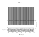
- An image of each row in the stripe image displayed on the flat-panel display may have a periodic signal of an equal wavelength, and the periodic signal may have a change in brightness in a wavelength of each period.
- the calculating of the raster parameter based on the captured stripe image may further include rectifying an image including the captured stripe image and calculating the raster parameter based on the captured stripe image.
- the raster parameter may be calculated based on a stripe image included in the rectified image
- the calculating of the raster parameter may include acquiring at least two image rows by performing sampling in the stripe image of the rectified image at preset or, alternatively, desired sampling intervals, acquiring a local period function T r (x; y r ) of a signal corresponding to an r th image row acquired through the sampling, wherein, in T r (x; y r ), x denotes a horizontal coordinate on the screen of the flat-panel display, y r denotes a vertical coordinate of the r th image row on the screen of the flat-panel display, r is a value of 1 through N, and N denotes a total number of image rows acquired through the sampling, calculating G r (x; y r ) corresponding to a gap between the screen of the flat-panel display and
- the calculating of the raster parameter based on the captured stripe image may include dividing the screen of the flat-panel display into at least two neighboring gratings ⁇ R ij ⁇ having the same size, wherein, in R ij , i is a value of 1 through N r and j is a value of 1 through N r , N r denotes a number of rows of a grating acquired through a division, and N c denotes a number of columns of the grating, calculating a gap G ij between the screen of the flat-panel display and a raster of the grating using a predetermined or, alternatively, desired method with respect to the respective grating R ij , G ij being a constant, and calculating a gap G(x, y) between the flat-panel display and the raster of the naked-eye 3D display, where
- the calculating of the raster parameter based on the captured stripe image may include generating a grating corresponding to a grating center point gradually and iteratively such that all regions on the screen of the flat-panel display cover the grating at least once, wherein the center point is generated based on a predetermined or, alternatively, desired random distribution and a size of the grating is determined in advance, and calculating G i corresponding to a gap between the screen of the flat-panel display and a raster of the grating using a predetermined or, alternatively, desired method with respect to the respective grating R ij , wherein G ij is a constant, i is a value of 1 through N s , N s denotes a total number of gratings, and G(x, y) corresponding to a gap between the calculated raster and the flat-panel display satis
- the calculating of the raster parameter based on the captured stripe image may include acquiring at least two sampling points by performing sampling on the screen of the flat-panel display and generating a grating in a predetermined or, alternatively, desired size based on each of the sampling points as a center point, calculating G pk corresponding to a gap between the screen of the flat-panel display and a raster of the grating using a predetermined or, alternatively, desired method for each grating R pk , wherein G pk is a constant, p is a value of 1 through N p , k is a value of 1 through N k , N p denotes a number of rows in the grating, and N k denotes a number of columns in the grating, and acquiring G(x, y) corresponding to a gap between the raster and the flat-panel display
- a method of acquiring the local period function of the signal corresponding to the r th image row may include calculating a number of pixels Num corresponding to a distance between neighboring peaks based on peaks, each acquired from the signal corresponding to the image row, wherein the distance between the neighboring peaks is Num*Ws/PixNum, Ws denotes a width of a raster area corresponding to a sampled stripe image, and PixNum denotes a number of pixels in the image row, and acquiring a local period function T r (x; y r ) of the signal corresponding to the image row by performing fitting on the distance between the neighboring peaks.
- a method of correcting the stereoscopic image displayed on the flat-panel display based on the calculated raster parameter may include acquiring a light beam model of the naked-eye 3D display based on the calculated raster parameter, and controlling the naked-eye 3D display to generate a stereoscopic image using the light beam model.
- Other example embodiments relate to an apparatus for correcting an image error in a naked-eye 3D display.
- the apparatus may include a display controller configured to control a flat-panel display displaying a stripe image, a raster parameter calculator configured to calculate a raster parameter of the naked-eye 3D display based on a captured stripe image, the captured stripe image being displayed after the stripe image displayed on the flat-panel display passes through a raster provided on a surface of the flat-panel display, and a stereoscopic image corrector configured to correct a stereoscopic image displayed on the naked-eye 3D display based on the calculated raster parameter, wherein the naked-eye 3D display includes the flat-panel display and the raster.
- An image of each row in the stripe image displayed on the flat-panel display may have a periodic signal of an equal wavelength, and the periodic signal may have a change in brightness in a wavelength of each period.
- the apparatus may further include an image rectifier configured to rectify an image including the captured stripe image before the raster parameter calculator calculates the raster parameter based on the captured stripe image, and the raster parameter calculator may be used by the image rectifier for a raster parameter of the naked-eye 3D display based on a stripe image of the rectified image.
- an image rectifier configured to rectify an image including the captured stripe image before the raster parameter calculator calculates the raster parameter based on the captured stripe image
- the raster parameter calculator may be used by the image rectifier for a raster parameter of the naked-eye 3D display based on a stripe image of the rectified image.
- the raster parameter calculator may include an image row sampler configured to acquire at least two image rows by performing sampling in the stripe image of the rectified image at preset or, alternatively, desired sampling intervals, a local period function acquirer configured to acquire a local period function T r (x; y r ) of a signal corresponding to an r th image row acquired through the sampling, wherein, in T r (x; y r ), x denotes a horizontal coordinate on the screen of the flat-panel display, y r denotes a vertical coordinate of the r th image row on the screen of the flat-panel display, r is a value of 1 through N, and N denotes a total number of image rows acquired through the sampling, a gap calculator configured to calculate G r (x; y r ) corresponding to a gap between the screen of the flat-panel display and a raster corresponding to
- the raster parameter calculator may include a divider configured to divide the screen of the flat-panel display into at least two neighboring gratings ⁇ R ij ⁇ having the same size, wherein, in R ij , i is a value of 1 through N r , j is a value of 1 through N c , N r denotes a number of rows of a grating acquired through a division, and N c denotes a number of columns of the grating, a grating gap calculator configured to calculate a gap G ij between the screen of the flat-panel display and a raster of the grating using a predetermined or, alternatively, desired method with respect to the respective grating R ij , G ij being a constant, and an overall gap calculator configured to calculate a gap G(x, y) between the flat-panel display and the raster of the
- the raster parameter calculator may include a grating generator configured to generate a grating corresponding to a grating center point gradually and iteratively such that all regions on the screen of the flat-panel display cover the grating at least once, wherein the center point is generated based on a predetermined or, alternatively, desired random distribution and a size of the grating is determined in advance, a grating gap calculator configured to calculate G i corresponding to a gap between the screen of the flat-panel display and a raster of the grating using a predetermined or, alternatively, desired method with respect to the respective grating R i , wherein G i is a constant, i is a value of 1 through N s , and N s denotes a total number of grating, and an overall gap calculator configured to calculate G(x, y) corresponding to a gap between the calculated raster and
- the raster parameter calculator may include a grating generator configured to acquire at least two sampling points by performing sampling on the screen of the flat-panel display and generate a grating in a predetermined or, alternatively, desired size based on each of the sampling points as a center point, a grating gap calculator configured to calculate G pk corresponding to a gap between the screen of the flat-panel display and a raster of the grating using a predetermined or, alternatively, desired method with respect to each grating R pk , wherein G pk is a constant, p is a value of 1 through N p , k is a value of 1 through N k , N p denotes a number of rows in the grating, and N k denotes a number of columns in the grating, and an overall gap calculator configured to acquire G(x, y) corresponding to a gap between
- the apparatus for correcting an image error in the naked-eye 3D display is configured to calculate a number of pixels Num corresponding to a distance between neighboring peaks based on peaks, each acquired from the signal corresponding to the image row, wherein the distance between the neighboring peaks is Num*Ws/PixNum, Ws denotes a width of a raster area corresponding to a sampled stripe image, and PixNum denotes a number of pixels in the image row, and acquire a local period function T r (x; y r ) of the signal corresponding to the image row by performing fitting on the distance between the neighboring peaks.
- the stereoscopic image correcting module may include a light beam model acquirer configured to acquire a light beam model of the naked-eye 3D display based on the calculated raster parameter, and a stereoscopic image generation controller configured to control the naked-eye 3D display to generate a stereoscopic image using the light beam model.
- the aforementioned contents may be applicable to a naked 3D display including a flat-panel display and a raster. It is possible to correct a stereoscopic image display on the naked-eye 3D display by controlling a stripe image displayed on the flat-panel display, capturing a stripe image after the stripe image displayed on the flat-panel display penetrates the raster, calculating a raster parameter of the naked-eye 3D display based on the captured stripe image, and adjusting a method of an image generated by the flat-panel display based on the calculated raster parameter. Through this, a quality of the stereoscopic image displayed on the naked-eye 3D display and a satisfaction of a user viewing the stereoscopic image may be enhanced.
- FIG. 1 illustrates an example of a naked-eye three-dimensional (3D) display according to at least one example embodiment
- FIGS. 2A through 2C illustrate examples of a naked 3D display having an error in a gap between a raster and a flat-panel display in comparison to the gap being an ideal value according to at least one example embodiment
- FIG. 3 illustrates an example of a method of correcting an image error in a naked-eye 3D display according to at least one example embodiment
- FIG. 4 illustrates an example of a stripe image displayed on a flat-panel display according to at least one example embodiment
- FIG. 5 illustrates an example of a relative position between a naked-eye 3D display and a capturing device according to at least one example embodiment
- FIG. 6 illustrates an example of a rectified image in comparison to an unrectified image according to at least one example embodiment
- FIG. 7 illustrates an example of a signal peak extracted from an image row according to at least one example embodiment
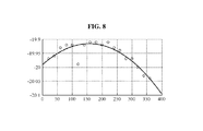
- FIG. 8 illustrates an example of a local period function of an image row acquired by performing fitting using a local signal period value according to at least one example embodiment
- FIG. 9 illustrates an example of a positional relationship between a coordinate system of a capturing device and a coordinate system of a screen of a flat-panel display according to at least one example embodiment
- FIG. 10 illustrates an example of a gap between a screen of a flat-panel display and a raster in a naked-eye 3D display, the gap which is acquired through a fitting based on a three-element set ⁇ [x c ,y r ,G r (x c ; y r )] ⁇ according to at least one example embodiment;
- FIG. 11 illustrates an example of dividing a screen of a flat-panel display into gratings according to at least one example embodiment
- FIG. 12 illustrates another example of dividing a screen of a flat-panel display into gratings according to at least one example embodiment
- FIG. 13 illustrates still another example of dividing a screen of a flat-panel display into gratings according to at least one example embodiment
- FIG. 14 illustrates an example of a screen direction vertical to a raster axis in a process of dividing a screen of a flat-panel display into gratings according to at least one example embodiment
- FIG. 15 illustrates an example of an apparatus of correcting an image error in a naked-eye 3D display according to at least one example embodiment
- FIG. 16 illustrates an example of a raster parameter calculator included in an apparatus for correcting an image error of a naked-eye 3D display according to at least one example embodiment
- FIG. 17 illustrates another example of a raster parameter calculator included in an apparatus for correcting an image error of a naked-eye 3D display according to at least one example embodiment
- FIG. 18 illustrates still another example of a raster parameter calculator included in an apparatus for correcting an image error of a naked-eye 3D display according to at least one example embodiment
- FIG. 19 illustrates an example of a stereoscopic image corrector included in an apparatus for correcting an image error in a naked-eye 3D display according to at least one example embodiment.
- first, second, A, B, (a), (b), and the like may be used herein to describe components.
- Each of these terminologies is not used to define an essence, order or sequence of a corresponding component but used merely to distinguish the corresponding component from other component(s). It should be noted that if it is described in the specification that one component is “connected”, “coupled”, or “joined” to another component, a third component may be “connected”, “coupled”, and “joined” between the first and second components, although the first component may be directly connected, coupled or joined to the second component.
- a raster may disperse light to represent different sub-pixel sets of a flat-panel display at different angles and positions in a region of view.
- the raster may be implemented as, for example, a slot raster, a liquid crystal display (LCD), and a lens array.
- FIG. 2A illustrates an example of an ideal arrangement of a raster and a flat-panel display.
- FIGS. 2B and 2C illustrate examples of a raster error that may occur in practice.
- a raster inclination error occurs in an example of FIG. 2B
- a non-linear raster transformation error occurs in an example of FIG. 2C .
- a method of correcting an image error of a naked-eye 3D display includes the following operations.
- a display controller may control a stripe image displayed on a flat-panel display.
- the display controller may control a display to display the stripe image such that, in the displayed stripe image, image rows may each be a periodic signal having the same wavelength and the periodic signal may have a change in brightness in a wavelength in each period.
- an image rectifier may calculate a raster parameter of the naked-eye 3D display based on a captured stripe image and the captured stripe image may be displayed after the stripe image displayed on the flat-panel display penetrates a raster.
- a stereoscopic image corrector may correct a stereoscopic image displayed on the naked-eye 3D display based on the calculated raster parameter.
- the displayed stripe image may be an image that is displayed through a raster, and the image displayed through the raster may be captured as the captured image.
- a brightness-periodicity changing stripe image displayed on the flat-panel image may also be referred to as a calibration stripe image.
- image rows may each be indicated by a periodic signal having the same periodicity and the periodic signal may have a change in brightness of a wavelength in each period.
- the periodic signal may be indicated by, for example, a period T c , and a phase position H.
- the periodic signal may be, but not limited to, a sine signal, a clock signal, or other type of periodical signal having a unit period.
- a stripe image having different frequency and orientation may be generated based on the calibration stripe image.
- the generated stripe image may also be referred to as, for example, an observation stripe image.
- An ideally readily used observation stripe image may allow a user to use a general capturing device for capturing, capture a picture of at least one observation stripe image in a normal viewing distance, and acquire a raster parameter of the naked-eye 3D display in operation 104 as below.
- the calibration stripe image may be generated using the following method.
- a raster gap P b
- an installation angle Slanted angle
- G b G b
- a designed viewing distance of the naked-eye 3D display D v based on a design value.
- the capturing device for example a camera, used by the user may capture the observation stripe image displayed on the naked-eye 3D display.
- the camera may be, for example, a digital camera.
- the digital camera may be, for example, a camera having one or more complementary metal oxide semiconductor (CMOS) image sensors and/or one or more charge-coupled device (CCD) image sensors.
- CMOS complementary metal oxide semiconductor
- CCD charge-coupled device
- a period of a stripe image observed on a screen of the flat-panel display screen may need to be greater than T min to perform extraction, and T min may be calculated according to Equation 1.
- T min 2* D v *tan( A m /2)* P m /R m [Equation 1]
- a period T 0 of the stripe image observed on the screen of the flap-panel display may be set to be within an appropriate range, for example, T min ⁇ T 0 ⁇ M*T min .
- a period T c of the calibration stripe image may be controlled using Equation 2.
- T c ( T 0 *T b )/( T o +T b ) [Equation 2]
- S1(x, y) corresponding to the calibration stripe image may be generated using Equation 3.
- S 1( x,y ) A 1*0.5*[sin( W c *( x ⁇ P 1))+1] [Equation 3]
- Equation 3 x and y denote respectively a horizontal coordinate and a vertical coordinate of a pixel of the calibration stripe image on the screen of the flat-panel display.
- A1 denotes an amplitude of the calibration stripe image and, for example, A1 may be set to be “255” for an 8-bit brightness image.
- P1 denote a total error in the calibration stripe image and may be set to be zero.
- a value applied to S1(x) may change in a range between 0 and A1.
- the image row may be a periodic signal. Since the periodic signal has the same wavelength in each period, the image row may have the same brightness change of a wavelength in each period.
- the image rectifier may calculate a raster parameter of the naked-eye 3D display based on a captured stripe image in operation 104 .
- the captured stripe image may be displayed after the stripe image displayed on the flat-panel display, for example, the calibration stripe image penetrates the raster.
- operation 104 may include two processes as below.
- An image including a captured stripe image may be rectified.
- a capturing device may capture an image with respect to the observation stripe image displayed on the naked-eye 3D display.
- the captured image may be rectified and property information on an accurate raster may be extracted from the rectified image.
- coordinate systems of the screen of the flat-panel display and the rectified image may be aligned through a rectification.
- an image of a capturing device may be inaccurately controlled.
- a difference in image conversion between the screen of the flat-panel display of a captured image and an actual screen may occur.
- the difference in image conversion may be determined based on, for example, a positional state of the capturing device and a lens parameter of the capturing device.
- the rectified image and a coordinate system of the screen of the flat-panel display may be aligned.
- the unrectified image may be shown in a left portion of FIG. 6
- the rectified image may be shown in a right portion of FIG. 6 .
- P s [x s ,y s ] may be coordinates of the corresponding pixel in the rectified image.
- a predetermined or, alternatively, desired pixel of the unrectified image and a corresponding pixel of the rectified image may satisfy Equation 4.
- u *[ x s ,y s ,1] T H *[ x i ,y i ,1] T [Equation 4]
- Equation 4 u denotes a constant representing a standardization factor, H denotes a homographic matrix.
- the homographic matrix H may be acquired through an extraction of a feature point using a least square method.
- four corner points of the screen of the flat-panel display may be set to be feature points.
- four corner points of the unrectified image may be A i , B i , C i , and D i
- four corner points of the rectified image may be A s , B s , C s , and D s .
- Coordinates of the four corner points in each of the unrectified image and the rectified image may be calculated based on a corner point extraction method.
- Coordinates of A i and A s , coordinates of B i and B s , coordinates of C i and C s , and coordinates of D i and D s may be substituted to Equation 4 so as to acquire the homographic matrix H using the least square method.
- the pixel coordinates may be converted into positional coordinates on the screen of the flat-panel display based on a length of a side of a tetragonal area corresponding to the pixel on the screen of the flat-panel display.
- the length of the side of the tetragonal area may be 1 millimeter (mm)
- pixel coordinates of a pixel of a zeroth column and a zeroth row are [0, 0]
- the pixel coordinates may be present outside an image in practice.
- pixel coordinates [x s , y s ] of a pixel of the rectified image may be converted into positional coordinates [l*x s ,l*y s ] on the screen of the flat-panel display.
- the raster parameter of the naked-eye 3D display may be calculated based on the stripe image in the rectified image. For example, a parameter associated with a gap between the raster and the screen of the flat-panel display, a parameter associated with a parallel translation of the raster relative to the screen of the flat-panel display, and a parameter associated with a rotation of the raster relative to the screen of the flat-panel display may be calculated.
- a method of calculating a raster parameter corresponding to a parameter associated with a gap between the raster and the screen of the flat-panel display is described with reference to the foregoing example.
- two methods of calculating the parameter associated with a gap between the raster and the screen of the flat-panel display will be described.
- a stripe image in a rectified image may be extracted and a sampling may be performed in the extracted stripe image at preset or, alternatively, desired sampling intervals. Through this, a group of image rows may be acquired. In this example, a region other than that of the screen of the flat-panel display may also be captured in practice. The image rows may be acquired through a sampling based on an equal-spacing scheme.
- a low-frequency pass filter may be used to filter the image rows acquired through the sampling and remove noise from the image rows. The following operations may be performed on an image row acquired through the sampling.
- a local period function acquirer may acquire peaks corresponding to the image row and calculate a number of pixels Num in a gap between neighboring peaks.
- the local period function acquirer may calculate a distance between the neighboring peaks based on the number of pixels Num.
- the local period function acquirer may acquire a local period function of a signal corresponding to the image row by performing fitting on the distance between the neighboring peaks.
- a size of a neighboring pixel for each pixel on the image row may be calculated.
- a local maximum value of the image row may be extracted and the extracted local maximum value may be stored as a signal peak value.
- the image row may be an ideal periodic signal, distances separating signal peaks may be equalized, and the distances may be the same as signal periods.
- the raster includes an error, a difference between signal peaks may occur.
- a distance between neighboring peaks may correspond to a local period of a signal.
- An image distance between neighboring peaks for example, the number of pixels Num in the gap between the neighboring peaks may be calculated and the image distance may be converted into a distance. Through this, the local period function corresponding to the image row may be calculated and acquired.
- PeakDist Num* Ws /PixNum [Equation 5]
- Ws denotes a width of a raster area corresponding to the extracted stripe image and PixNum denotes a number of pixels of an image row.
- a local period function T r (x; y r ) of a signal corresponding to the image row may be acquired through a fitting of a local period value, for example, the distance between the neighboring peaks.
- x represents a horizontal coordinate on the screen of the flat-panel display
- y r represents a vertical coordinate of an r th image row on the screen of the flat-panel display
- r is a value of 1 through N
- N denotes a total number of image rows acquired through the sampling.
- G r (x; y r ) D cam *(1 ⁇ P x /Tsr ( x;y r ))) [Equation 6]
- Equation 6 D cam denotes a distance between the capturing device used for capturing and the screen of the flat-panel display and P x denotes a horizontal raster gap.
- Tsr(x; y r ) may be a period change function for which the capturing device performs sampling through a penetration of the raster relative to the screen of the flat-panel display
- Tsr(x; y r ) T r (y r )*T r (x; y r )/(T r (x; y r ) ⁇ T c (y r ))
- T c (y r ) being a period of the r th image row.
- D cam may be acquired using one camera pose calculator.
- the capturing device may calculate an attitude R c and a position T c with respect to a coordinate system on the screen of the flat-panel display and acquire D cam .
- K c denotes a known parameter in the capturing device.
- Equation 8 used for simplification may be acquired as shown below.
- u *[ x i ,y i ,1] T K c *[ r 1 r 2 T x ]*[ X i ,Y i ,1] T [Equation 8]
- R c [r 1 r 2 r 3 ], r 1 , r 2 may be a first column and a second column of the rotation matrix R c , and K c may be a 3 ⁇ 3 matrix.
- [r 1 r 2 T c ] u*K c ⁇ 1 *H.
- r 3 and T c may be acquired based on a unit orthogonality of the rotation matrix the capturing device may further acquire the position T c and the attitude R c of the coordinate system on the screen of the flat-panel display.
- an image row neighboring the r th image row may be used in a process of calculating G r (x; y r ) to reduce an adverse effect of noise.
- G 1 (x; y 1 ), G 2 (x; y 2 ), . . . , G r (x; y r ), G N (x; y N ) corresponding to gap values between the flat-panel display and a group of rasters may be acquired with reference to FIG. 10 .
- one three-element set ⁇ [x c ,y r ,G r (x c ; y r )] ⁇ may be acquired.
- all predetermined or, alternatively, desired elements [x c ,y r ,G r (x c ; y r )] may be one three-element.
- all coordinates corresponding to [x c , y r ] may be distributed on the screen of the flat-panel display.
- a gap function G(x, y) between the screen of the flat-panel display and the raster may be acquired.
- G(x, y) represent coordinates of a position of a predetermined or, alternatively, desired point on the screen of the flat-panel display.
- the screen of the flat-panel display may be divided into a plurality of local regions.
- the gap value may be calculated for each of the local regions. Based on the gap value, a gap between the screen of the flat-panel display and a raster corresponding to the entire screen of the flat-panel display may be calculated.
- the gap between the screen of the flat-panel display and the raster corresponding to the entire screen of the flat-panel display may be calculated using the following schemes.
- the screen of the flat-panel display may be divided into a plurality of neighboring gratings having the same size.
- i may be a value of 1 through N r and j may be a value of 1 through N c .
- a gap between the screen of the flat-panel display and the raster corresponding to each of the gratings may be a value of a constant.
- An N th image row may be acquired by performing sampling in a stripe image of a grating R ij at preset or, alternatively, desired sampling intervals for each of the gratings ⁇ R ij ⁇ .
- Operations S 202 through S 208 may be performed on each image row acquired through the sampling to acquire a gap G r (x; y r ) between the screen of the flat-panel display and a raster corresponding to each image row.
- gap values G 1 (x; y 1 ), G 2 (x; y 2 ), . . . , G r (x; y r ), . . .
- G N (x; y N ) between the flat-panel display and a group of rasters may be acquired.
- G r (x; y r )/N may be calculated and an x-directional average value may be calculated using G(x).
- a gap G ij between the screen of the flat-panel display and the raster corresponding to the grating R ij may be acquired.
- (x, y) may be coordinates of a position of a predetermined or, alternatively, desired point on the screen of the flat-panel display.
- a center point [x i , y i ] of a plurality of gratings ⁇ R i ⁇ may be generated based on a predetermined or, alternatively, desired random distribution, for example, an equalized distribution and generate a grating corresponding thereto.
- i may be a value of 1 through N i .
- the center point may be continually generated based on the random distribution through iterations such that all regions on the screen of the flat-panel display cover the grating at least once.
- a gap between the screen of the flat-panel display and the raster corresponding to each grating may be a value of a constant.
- an N th image row may be acquired by performing sampling in a stripe image of the grating R i at preset or, alternatively, desired sampling intervals.
- Operations S 202 through S 208 may be performed on each image row acquired through the sampling to acquire a gap G r (x; y r ) between the screen of the flat-panel display and a raster corresponding to each image row.
- gap values G 1 (x; y 1 ), G 2 (x; y 2 ), . . . , G r (x; y r ), . . .
- G N (x; y N ) between the flat-panel display and a group of rasters may be acquired.
- G r (x; y r )/N may be calculated and an x-directional average value may be calculated based on G(x).
- a gap G i between the screen of the flat-panel display and the raster corresponding to the grating R i may be acquired.
- the gap G(x, y) between the screen of the flat-panel display and the raster corresponding to, the entire screen of the flat-panel display may satisfy Equation 10.
- (x, y) may be coordinates of a position of a predetermined or, alternatively, desired point on the screen of the flat-panel display.
- a group of sampling points may be acquired through a sampling performed on the screen of the flat-panel display, and a grating may be generated based on each of the sampling points as a center point.
- a plurality of gratings ⁇ R pk ⁇ may be acquired.
- p is a value of 1 through N p
- k is a value of 1 through N k .
- a gap between center points of neighboring gratings may be equalized.
- the neighboring gratings may separate from each other and also overlap each other.
- a gap between the screen of the flat-panel display and the raster corresponding to each of the gratings may be a value of a constant.
- an N th image row may be acquired by performing sampling in a stripe image of the grating R pk at preset or, alternatively, desired sampling intervals.
- Operations S 202 through S 208 may be performed on each image row acquired through the sampling to acquire a gap G r (x; y r ) between the screen of the flat-panel display and a raster corresponding to each image row.
- gap values G 1 (x; y 1 ), G 2 (x; y 2 ), . . . , G r (x; y r ), . . .
- G N (x; y N ) between the flat-panel display and a group of rasters may be acquired.
- G r (x; y r )/N may be calculated and an x-directional average value may be calculated based on G(x).
- a gap G pk between the screen of the flat-panel display and the raster corresponding to the grating R pk may be acquired.
- the gap G(x, y) between the flat-panel display and the raster corresponding to the entire screen of the flat-panel display may be acquired.
- G(x, y) may be one consecutive two-dimensional (2D) function, and (x, y) denotes positional coordinates of a predetermined or, alternatively, desired point on the screen of the flat-panel display.
- a sampling point may be the same as a value of the gap between the screen of the flat-panel display and a raster corresponding to the interpolation point in the three-element set ⁇ [x pk , y pk , G pk ] ⁇ .
- a b a tan [(( P 1 ( y )/ T r ( y ))+( P r ( y )/ T sr ( y )) ⁇ ( P r ( y )/ T c ( y )))/(((1/ T c ( y )) ⁇ (1/ T r ( y ))* y )] [Equation 11]
- a calculation accuracy of A b may increase using an average value acquired through a calculation performed on a plurality of
- the stereoscopic image corrector may correct the stereoscopic image displayed on the naked-eye 3D display based on the raster parameter calculated in operation 104 .
- a light beam model of the naked-eye 3D display may be acquired by computing a light beam corresponding to each pixel on the flat-panel display based on the gap G(x, y) between the screen of the flat-panel display and the raster calculated in operation 104 .
- What the light beam model indicates may be a 3D light beam corresponding to each pixel on the flat-panel display penetrating the raster toward a user observation space.
- the naked-eye 3D display may correct a stereoscopic image error due to a raster transformation through a rendering or a light field image conversion, thereby generating an enhanced stereoscopic image.
- such stereoscopic image may include a number of viewpoints differing for each image.
- a binocular stereoscopic angle image may include left and right viewpoints.
- a prism lens or a slot raster-based stereoscopic image may include a few, for example, tens of viewpoints or less distributed in a horizontal direction.
- a lens array raster-based stereoscopic image may include tens of hundreds of viewpoints distributed in a spatial region.
- the foregoing method may be applicable to a naked-eye 3D display including a flat-panel display and a raster.
- the method may be performed by controlling the flat-panel display to display a stripe image, capturing a stripe image displayed after the stripe image displayed on the flat-panel display penetrates the raster, calculating a raster parameter of the naked-eye 3D display based on the captured stripe image, adjusting a method of generating an image in the flat-panel display based on the calculated raster parameter, and correcting a stereoscopic image displayed on the naked-eye 3D display.
- a quality of the stereoscopic image displayed on the naked-eye 3D display may increase and a quality of a stereoscopic image viewed by a user may also increase.
- a predetermined or, alternatively, desired stripe image may be output by the flat-panel display.
- Each image row of the stripe image may be a periodic signal having an equal wavelength.
- the periodic signal may have a change in brightness in a wavelength of each period and each image row may have a periodic signal of a predetermined or, alternatively, desired frequency.
- a measurable image used to increase a local error through a mole stripe phenomenon may be generated.
- high definition image is to be captured using a general capturing device, for example, a camera in a normal viewing distance, a user may not need to capture in a short distance and a difficulty in capturing may also be alleviated.
- a gap function of the raster and the screen of the flat-panel display may be acquired using the method described in the foregoing example.
- a gap value corresponding to each pixel of the flat-panel display may be acquired.
- the aforementioned method may be applicable to a situation in which gaps between rasters corresponding to different pixels on the flat-panel display and the screen of the flat-panel display are different from one another, and a situation in which a dynamic change occurs in the gaps between the rasters and the flat-panel display.
- a deformation occurring when a material of the raster is expanded due to a heat or compressed by a pressure may cause a change in the gap between the raster and the screen of the flat-panel display.
- the method of calculating a gap between the raster and the screen of the flat-panel display may be widely applicable and suitable for an actual situation.
- an apparatus 300 may be an apparatus for correcting an image error of a naked-eye 3D display.
- the apparatus 300 may include a display controller 301 , an image rectifier 302 , a raster parameter calculator 303 , and a stereoscopic image corrector 304 .
- the display controller 301 may control the flat-panel display to display a stripe image.
- the image rectifier 302 may rectify an image including a stripe image captured by the raster parameter calculator 303 based on the captured stripe image before calculating a raster parameter of a naked-eye 3D display.
- the raster parameter calculator 303 may calculate the raster parameter of the naked-eye 3D display based on the captured stripe image such that the captured stripe image corresponding to the stripe image displayed on the flat-panel display is displayed after penetrating the raster.
- the stereoscopic image corrector 304 may correct a stereoscopic image displayed on the naked-eye 3D display based on the raster parameter calculated by the raster parameter calculator 303 .
- the apparatus 300 may include or be implemented by one or more circuits or circuitry (e.g., hardware) specifically structured to carry out and/or control some or all of the operations described in the present disclosure as being performed by the apparatus 300 (or an element thereof).
- the apparatus 300 may include or be implemented by a memory and one or more processors executing computer-readable code (e.g., software and/or firmware) that is stored in the memory and includes instructions for causing the one or more processors to carry out and/or control some or all of the operations described herein as being performed by the apparatus 300 (or an element thereof).
- the apparatus 300 may be implemented by, for example, a combination of the above-referenced hardware and one or more processors executing computer-readable code.
- any or all of the display controller 301 , image rectifier 302 , raster parameter calculator 303 , stereoscopic image corrector 304 , and elements thereof may be implemented by one or both of the above-referenced (i) hardware and (ii) one or more processors executing computer-readable code.
- each of the one or more processors may be a hardware-implemented data processing device having circuitry that is physically structured to execute desired operations including, for example, operations represented as code and/or instructions included in a program.
- desired operations including, for example, operations represented as code and/or instructions included in a program.
- the above-referenced hardware-implemented data processing device include, but are not limited to, a microprocessor, a central processing unit (CPU), a processor core, a multi-core processor; a multiprocessor, an application-specific integrated circuit (ASIC), and a field programmable gate array (FPGA).
- processors executing program code are programmed processors, and thus, are special-purpose computers.
- Each image row of the stripe image displayed on the flat-panel display may have the same wavelength of a period function, and a wavelength of each period function may have a change in brightness.
- the raster parameter calculator 303 may include an image row sampler 3031 , a local period function acquirer 3032 , a gap calculator 3033 , and a fitting unit 3034 .
- the image row sampler 3031 may acquire at least two image rows by performing sampling in a stripe image of an image rectified by the image rectifier 302 at preset or, alternatively, desired sampling intervals.
- the local period function acquirer 3032 may acquire a local period function T r (x; y r ) of a signal corresponding to an r th image row acquired by the image row sampler 3031 through the sampling.
- T r (x; y r )
- x denotes a horizontal coordinate on the screen of the flat-panel display
- y r denotes a vertical coordinate of the r th image row on the screen of the flat-panel display
- r is a value of 1 through N
- N denotes a total number of image rows acquired through the sampling.
- the fitting unit 3034 may acquire a gap G(x, y) between the raster and the flat-panel display by performing fitting based on a three-element set ⁇ [x c ,y r ,G r (x; y r )] ⁇ .
- the raster parameter calculator 303 may include a divider 3035 , a grating gap calculator 3037 , and an overall gap calculator 3038 .
- the divider 3035 may divide the screen of the flat-panel display into at least two neighboring gratings ⁇ R ij ⁇ having the same size, i being a value of 1 through N r and j being a value of 1 through N c .
- N r denotes a number of rows of a grating acquired through a division
- N c denotes a number of columns of the grating.
- the grating gap calculator 3037 may calculate a gap G ij between the screen of the flat-panel display and a raster of the grating using a predetermined or, alternatively, desired method for each of the gratings ⁇ R ij ⁇ acquired through the division performed by the divider 3035 , G ij being a constant.
- the predetermined or, alternatively, desired method may include an operation of acquiring at least two image rows by sampling a stripe image corresponding to the gratings and the rectified image at preset or, alternatively, desired sampling intervals, an operation of acquiring a local period function T r (x; y r ) of a signal corresponding to an r th image row acquired through the sampling, wherein, in T r (x; y r ), x denotes a horizontal coordinate on the screen of the flat-panel display, y r denotes a vertical coordinate of the r th image row on the screen of the flat-panel display, r is a value of 1 through N, and N denotes a total number of image rows acquired through the sampling, an operation of calculating G r (x; y r ) corresponding to a distance between the flat-panel display and a raster corresponding to the r th image row, G r (x; y r ) satisfying the following equations: G
- the raster parameter calculator 303 may include a grating generator 3036 , the grating gap calculator 3037 , and the overall gap calculator 3038 .
- the grating generator 3036 may generate a grating corresponding to a grating center point gradually and iteratively such that all regions on the screen of the flat-panel display cover the grating at least once.
- the center point may be generated based on a predetermined or, alternatively, desired random distribution and a size of the grating may be determined in advance.
- the grating gap calculator 3037 may calculate G i corresponding to a gap between the screen of the flat-panel display and a raster of the grating using a predetermined or, alternatively, desired method for each of the gratings R ij generated by the grating generator 3036 .
- G ij is a constant
- i is a value of 1 through N s
- N s denotes a total number of grating.
- an operation of acquiring at least two image rows by performing sampling in a stripe image corresponding to the grating and the rectified image at preset or, alternatively, desired sampling intervals an operation of acquiring a local period function T r (x; y r ) of a signal corresponding to an r th image row acquired through the sampling, wherein, in T r (x; y r ), x denotes a horizontal coordinate on the screen of the flat-panel display, y r denotes a vertical coordinate of the r th image row on the screen of the flat-panel display, r is a value of 1 through N, and N denotes a total number of image rows acquired through the sampling, an operation of calculating G r (x; y r ) corresponding to a gap between the flat-panel display and a raster corresponding to the r th image row, G r (x; y r ) satisfying the following equations: G r (x; y r )
- the raster parameter calculator 303 may also include the grating generator 3036 , the grating gap calculator 3037 , and the overall gap calculator 3038 .
- the grating generator 3036 may acquire at least two sampling points by performing sampling on the screen of the flat-panel display and generate a grating in a predetermined or, alternatively, desired size based on each of the sampling points as a center point.
- the grating gap calculator 3037 may calculate G pk corresponding to a gap between the screen of the flat-panel display and a raster of the grating using a predetermined or, alternatively, desired method with respect to each grating R pk generated by the grating generator 3036 .
- the overall gap calculator 3038 may acquire G(x, y) corresponding to a gap between the flat-panel display and the raster of the naked-eye 3D display through an interpolation of a three-element set ⁇ [x pk . y pk , G pk ] ⁇ . In the three-element set ⁇ [x pk .
- the overall gap calculator 3038 may acquire at least two image rows by performing sampling in a stripe image corresponding to the grating and the rectified image at preset or, alternatively, desired sampling intervals, and acquire a local period function T r (x; y r ) of a signal corresponding to an r th image row acquired through the sampling.
- T r (x; y r )
- x denotes a horizontal coordinate on the screen of the flat-panel display
- y r denotes a vertical coordinate of the r th image row on the screen of the flat-panel display
- r is a value of 1 through N
- N denotes a total number of image rows acquired through the sampling.
- G r (x; y r ) corresponding to a gap between the flat-panel display and a raster corresponding to the r th image row
- G r (x; y r ) may satisfy the following equations:
- G r (x; y r ) D cam *(1 ⁇ (P x /Tsr(x; y r )))
- D cam denotes a distance between the screen of the flat-panel display and the capturing device
- P x denotes a horizontal raster interval of the raster
- Tsr(x; y r ) is a period change function for which the capturing device performs sampling by penetrating the raster relative to the screen of the flat-panel display
- Tsr(x; y r ) T c (y r )*T r (x; y r )/(T r (x; y r ) ⁇ T c (y r ))
- a scheme of acquiring a local period function of a signal corresponding to an image row may include a scheme of acquiring peaks of the signal corresponding to the image row and calculating a number of pixels Num included in a gap between neighboring peaks, a scheme of setting a calculated distance between neighboring peaks to be “Num*Ws/PixNum”.
- Ws denotes a width of a raster area corresponding to a sampled stripe image
- PixNum denotes a number of pixels in the image row.
- the scheme of acquiring a local period function of a signal corresponding to an image row may include a scheme of acquiring a local period function T r (x; y r ) of the signal corresponding to the image row by performing fitting on a distance between neighboring peaks.
- the stereoscopic image corrector 304 may include a light beam model acquirer 3041 and a stereoscopic image generation controller 3042 .
- the light beam model acquiring unit 3041 may acquire a light beam model of a naked-eye 3D display based on the calculated raster parameter calculated by the raster parameter calculator 303 .
- the stereoscopic image generation control unit 3042 may control the naked-eye 3D display to generate a stereoscopic image using the light beam model acquired by the light beam model acquiring unit 3041 .
- the examples may be applicable to a naked-eye 3D display including a flat-panel display and a raster.
- the method may be performed by controlling the flat-panel display to display a stripe image, capturing a stripe image displayed after the stripe image displayed on the flat-panel display penetrates the raster, calculating a raster parameter of the naked-eye 3D display based on the captured stripe image, adjusting a method of generating an image in the flat-panel display based on the calculated raster parameter, and correcting a stereoscopic image displayed on the naked-eye 3D display.
- a quality of the stereoscopic image displayed on the naked-eye 3D display may increase and a quality of a stereoscopic image viewed by a user may also increase.
- a predetermined or, alternatively, desired stripe image may be output by the flat-panel display.
- Each image row of the stripe image may be a periodic signal having an equal wavelength.
- the periodic signal may have a change in brightness in a wavelength of each period and each image row may have a periodic signal of a predetermined or, alternatively, desired frequency.
- a measurable image used to increase a local error through a mole stripe phenomenon may be generated.
- high definition image is to be captured using a general capturing device, for example, a camera in a normal viewing distance, a user may not need to capture in a short distance and a difficulty in capturing may also be alleviated.
- a gap function of the raster and the screen of the flat-panel display may be acquired using the method described in the foregoing example.
- a gap value corresponding to each pixel of the flat-panel display may be acquired.
- the aforementioned method may be applicable to a situation in which gaps between rasters corresponding to different pixels on the flat-panel display and the screen of the flat-panel display are different from one another, and a situation in which a dynamic change occurs in the gaps between the rasters and the flat-panel display.
- a deformation occurring when a material of the raster is expanded due to a heat or compressed by a pressure may cause a change in the gap between the raster and the screen of the flat-panel display.
- the method of calculating a gap between the raster and the screen of the flat-panel display may be widely applicable and suitable for an actual situation.
- the units and/or modules described herein may be implemented using hardware components and software components.
- the hardware components may include microphones, amplifiers, band-pass filters, audio to digital convertors, and processing devices.
- a processing device may be implemented using one or more hardware device configured to carry out and/or execute program code by performing arithmetical, logical, and input/output operations.
- the processing device(s) may include a processor, a controller and an arithmetic logic unit, a digital signal processor, a microcomputer, a field programmable array, a programmable logic unit, a microprocessor or any other device capable of responding to and executing instructions in a defined manner.
- the processing device may run an operating system (OS) and one or more software applications that run on the OS.
- OS operating system
- the processing device also may access, store, manipulate, process, and create data in response to execution of the software.
- a processing device may include multiple processing elements and multiple types of processing elements.
- a processing device may include multiple processors or a processor and a controller.
- different processing configurations are possible, such a parallel processors.
- the software may include a computer program, a piece of code, an instruction, or some combination thereof, to independently or collectively instruct and/or configure the processing device to operate as desired, thereby transforming the processing device into a special purpose processor.
- Software and data may be embodied permanently or temporarily in any type of machine, component, physical or virtual equipment, computer storage medium or device, or in a propagated signal wave capable of providing instructions or data to or being interpreted by the processing device.
- the software also may be distributed over network coupled computer systems so that the software is stored and executed in a distributed fashion.
- the software and data may be stored by one or more non-transitory computer readable recording mediums.
- the methods according to the above-described example embodiments may be recorded in non-transitory computer-readable media including program instructions to implement various operations of the above-described example embodiments.
- the media may also include, alone or in combination with the program instructions, data files, data structures, and the like.
- the program instructions recorded on the media may be those specially designed and constructed for the purposes of example embodiments, or they may be of the kind well-known and available to those having skill in the computer software arts.
- non-transitory computer-readable media examples include magnetic media such as hard disks, floppy disks, and magnetic tape; optical media such as CD-ROM discs, DVDs, and/or Blue-ray discs; magneto-optical media such as optical discs; and hardware devices that are specially configured to store and perform program instructions, such as read-only memory (ROM), random access memory (RAM), flash memory (e.g., USB flash drives, memory cards, memory sticks, etc.), and the like.
- program instructions include both machine code, such as produced by a compiler, and files containing higher level code that may be executed by the computer using an interpreter.
- the above-described devices may be configured to act as one or more software modules in order to perform the operations of the above-described example embodiments, or vice versa.
Landscapes
- Engineering & Computer Science (AREA)
- Multimedia (AREA)
- Signal Processing (AREA)
- Physics & Mathematics (AREA)
- Computer Hardware Design (AREA)
- General Physics & Mathematics (AREA)
- Theoretical Computer Science (AREA)
- Control Of Indicators Other Than Cathode Ray Tubes (AREA)
- Controls And Circuits For Display Device (AREA)
Abstract
Description
T min=2*D v*tan(A m/2)*P m /R m [Equation 1]
T c=(T 0 *T b)/(T o +T b) [Equation 2]
S1(x,y)=A1*0.5*[sin(W c*(x−P1))+1] [Equation 3]
u*[x s ,y s,1]T =H*[x i ,y i,1]T [Equation 4]
PeakDist=Num*Ws/PixNum [Equation 5]
G r(x;y r)=D cam*(1−P x /Tsr(x;y r))) [Equation 6]
u*[x i ,y i,1]T =K c*[R c T c]*[X i ,Y i ,Z i,1]T [Equation 7]
u*[x i ,y i,1]T =K c*[r 1 r 2 T x]*[X i ,Y i,1]T [Equation 8]
If [x,y]∈R ij ,G(x,y)=G ij [Equation 9]
A b =a tan [((P 1(y)/T r(y))+(P r(y)/T sr(y))−(P r(y)/T c(y)))/(((1/T c(y))−(1/T r(y)))*y)] [Equation 11]
Claims (20)
S1(x,y)=A1*0.5*[sin(W c*(x−P1))+1]
W c=2π/T c ,T c=(T o *T b)/(T o +T b)
T min <T o <M*T min
T min=2*D v*tan(A m/2)*P m /R m
u*[x s ,y s,1]T =H*[x i ,y i,1]T
G r(x;y r)=D cam*(1−(P x /Tsr(x;y r)))
Tsr(x;y r)=T c(y r)*T r(x;y r)/(T r(x;y r)−T c(y r))
G(x,y)=Gij,
G r(x;y r)=D cam*(1−(P x /Tsr(x;y r)))
Tsr(x;y r)=T c(y r)*T r(x;y r)/(T r(x;y r)−T c(y r))
G(x,y)=(1/N a)*Σi=1 N
G r(x;y r)=D cam*(1−(P x /Tsr(x;y r)))
Tsr(x;y r)=T c(y r)*T r(x;y r)/(T r(x;y r)−T c(y r))
G r(x;y r)=D cam*(1−(P x /Tsr(x;y r)))
Tsr(x;y r)=T c(y r)*T r(x;y r)/(T r(x;y r)−T c(y r))
S1(x,y)=A1*0.5[sin(W c*(x−P1))+1]
W c=2π/T c ,T c=(T o *T b)/(T o +T b)
T min <T o <M*T min
T min=2*D v*tan(A m/2)*P m /R m
u*[x s ,y s ,l]T =H*[x i ,y i ,l]T
G r(x;y r)=D cam*(1−(P x /Tsr(x;y r)))
Tsr(x;y r)=T c(y r)*T r(x;y r)/(T r(x;y r)−T c(y r))
G r(x;y r)=D cam*(1−(P x /Tsr(x;y r)))
Tsr(x;y r)=T c(y r)*T r(x;y r)/(T r(x;y r)−T c(y r))
G(x,y)=(1/N a)*Σi=1 N
G r(x;y r)=D cam*(1−(P x /Tsr(x;y r)))
Tsr(x;y r)=T c(y r)*T r(x;y r)/(T r(x;y r)−T c(y r))
G r(x;y r)=D cam*(1−(P x /Tsr(x;y r)))
Tsr(x;y r)=T c(y r)*T r(x;y r)/(T r(x;y r)−T c(y r))
Applications Claiming Priority (5)
| Application Number | Priority Date | Filing Date | Title |
|---|---|---|---|
| CN201610055821.4A CN107018402B (en) | 2016-01-27 | 2016-01-27 | Image error correction method and device for naked eye three-dimensional display |
| CN201610055821 | 2016-01-27 | ||
| CN201610055821.4 | 2016-01-27 | ||
| KR10-2016-0110120 | 2016-08-29 | ||
| KR1020160110120A KR102550930B1 (en) | 2016-01-27 | 2016-08-29 | Autostereoscopic display with efficient barrier parameter estimation method |
Publications (2)
| Publication Number | Publication Date |
|---|---|
| US20170214900A1 US20170214900A1 (en) | 2017-07-27 |
| US10440344B2 true US10440344B2 (en) | 2019-10-08 |
Family
ID=59359747
Family Applications (1)
| Application Number | Title | Priority Date | Filing Date |
|---|---|---|---|
| US15/416,240 Active 2037-06-05 US10440344B2 (en) | 2016-01-27 | 2017-01-26 | Method and apparatus for correcting image error in naked-eye three-dimensional (3D) display |
Country Status (1)
| Country | Link |
|---|---|
| US (1) | US10440344B2 (en) |
Families Citing this family (7)
| Publication number | Priority date | Publication date | Assignee | Title |
|---|---|---|---|---|
| CN114554174B (en) * | 2020-11-25 | 2024-04-02 | 京东方科技集团股份有限公司 | Naked eye three-dimensional image measuring system, image processing method and device and display equipment |
| CN115136227B (en) * | 2020-11-30 | 2023-11-17 | 京东方科技集团股份有限公司 | Display device and display method thereof |
| CN112767317B (en) * | 2020-12-31 | 2022-11-25 | 上海易维视科技有限公司 | Naked eye 3D display grating film detection method |
| CN113242420B (en) * | 2021-04-22 | 2022-08-05 | 深圳市创鑫未来科技有限公司 | Stereo calibration chart and method for manually calibrating stereo display picture |
| CN115988192B (en) * | 2022-12-21 | 2025-04-25 | 京东方科技集团股份有限公司 | Naked eye 3D parameter calibration method, device, electronic equipment and storage medium |
| CN115831043B (en) * | 2023-02-14 | 2023-05-12 | 长春希达电子技术有限公司 | Device and method for correcting bright and dark lines of virtual pixel display screen |
| CN118555383B (en) * | 2024-05-27 | 2024-11-15 | 安徽惜贤科技有限公司 | A naked eye 3D image processing method |
Citations (10)
| Publication number | Priority date | Publication date | Assignee | Title |
|---|---|---|---|---|
| US6366281B1 (en) * | 1996-12-06 | 2002-04-02 | Stereographics Corporation | Synthetic panoramagram |
| JP2007065441A (en) | 2005-09-01 | 2007-03-15 | Namco Bandai Games Inc | Arrangement lens specification deriving method, program, information storage medium, and arrangement lens specification deriving device |
| US20070109320A1 (en) * | 2002-05-15 | 2007-05-17 | Sabrina Skibak | Image synthesis by rank-1 lattices |
| US20100220325A1 (en) * | 2007-06-07 | 2010-09-02 | Stephan Otte | Method for orienting an optical element on a screen |
| US20130182083A1 (en) * | 2012-01-12 | 2013-07-18 | Seefront Gmbh | Calibration of an autostereoscopic display system |
| JP2013190713A (en) | 2012-03-15 | 2013-09-26 | Sony Corp | Display device and method, information processing device and method, and program |
| US20130258057A1 (en) * | 2012-03-29 | 2013-10-03 | Nao Mishima | Image processing device, autostereoscopic display device, image processing method and computer program product |
| JP5354252B2 (en) | 2008-05-13 | 2013-11-27 | 独立行政法人情報通信研究機構 | 3D display manufacturing system, 3D display system, and 3D display system manufacturing method |
| KR101340798B1 (en) | 2007-03-27 | 2013-12-11 | 엘지디스플레이 주식회사 | Fabricating method of a Three-dimensional image display |
| KR20140071638A (en) | 2012-12-04 | 2014-06-12 | 한국전자통신연구원 | Image-based methods and apparatus for compensating optical lens distortion of digital holographic printer system |
-
2017
- 2017-01-26 US US15/416,240 patent/US10440344B2/en active Active
Patent Citations (10)
| Publication number | Priority date | Publication date | Assignee | Title |
|---|---|---|---|---|
| US6366281B1 (en) * | 1996-12-06 | 2002-04-02 | Stereographics Corporation | Synthetic panoramagram |
| US20070109320A1 (en) * | 2002-05-15 | 2007-05-17 | Sabrina Skibak | Image synthesis by rank-1 lattices |
| JP2007065441A (en) | 2005-09-01 | 2007-03-15 | Namco Bandai Games Inc | Arrangement lens specification deriving method, program, information storage medium, and arrangement lens specification deriving device |
| KR101340798B1 (en) | 2007-03-27 | 2013-12-11 | 엘지디스플레이 주식회사 | Fabricating method of a Three-dimensional image display |
| US20100220325A1 (en) * | 2007-06-07 | 2010-09-02 | Stephan Otte | Method for orienting an optical element on a screen |
| JP5354252B2 (en) | 2008-05-13 | 2013-11-27 | 独立行政法人情報通信研究機構 | 3D display manufacturing system, 3D display system, and 3D display system manufacturing method |
| US20130182083A1 (en) * | 2012-01-12 | 2013-07-18 | Seefront Gmbh | Calibration of an autostereoscopic display system |
| JP2013190713A (en) | 2012-03-15 | 2013-09-26 | Sony Corp | Display device and method, information processing device and method, and program |
| US20130258057A1 (en) * | 2012-03-29 | 2013-10-03 | Nao Mishima | Image processing device, autostereoscopic display device, image processing method and computer program product |
| KR20140071638A (en) | 2012-12-04 | 2014-06-12 | 한국전자통신연구원 | Image-based methods and apparatus for compensating optical lens distortion of digital holographic printer system |
Also Published As
| Publication number | Publication date |
|---|---|
| US20170214900A1 (en) | 2017-07-27 |
Similar Documents
| Publication | Publication Date | Title |
|---|---|---|
| US10440344B2 (en) | Method and apparatus for correcting image error in naked-eye three-dimensional (3D) display | |
| KR102415501B1 (en) | Method for assuming parameter of 3d display device and 3d display device thereof | |
| KR102370062B1 (en) | Method of determining calibration parameter for 3d display device and 3d display device thereof | |
| CN104103058B (en) | Image matching system and method | |
| CN105988224B (en) | Three-dimensional display device and its moire reduction method and device | |
| US20140211286A1 (en) | Apparatus and method for generating digital hologram | |
| US10783607B2 (en) | Method of acquiring optimized spherical image using multiple cameras | |
| US10270957B2 (en) | Method and apparatus for generating an adapted slice image from a focal stack | |
| EP3523777A1 (en) | System and method for rectifying a wide-angle image | |
| CN103813150A (en) | Image processing apparatus and method, image processing system and program | |
| US20160371842A1 (en) | Method and apparatus for computing an estimate position of a micro-image produced by a micro-lens of an array of micro-lenses of an optical acquisition system | |
| US20180139437A1 (en) | Method and apparatus for correcting distortion | |
| JP6717576B2 (en) | Video rendering apparatus and method | |
| JP6365303B2 (en) | Image processing apparatus and image processing method | |
| US10126562B2 (en) | Apparatus and methods for reducing moire fringe | |
| US10366527B2 (en) | Three-dimensional (3D) image rendering method and apparatus | |
| JP4778569B2 (en) | Stereo image processing apparatus, stereo image processing method, and stereo image processing program | |
| US10008030B2 (en) | Method and apparatus for generating images | |
| US9538075B2 (en) | Frequency domain processing techniques for plenoptic images | |
| US9769358B2 (en) | Information processing apparatus, information processing method, and storage medium | |
| Ishii et al. | Wide-baseline stereo matching using ASIFT and POC | |
| Li et al. | Accurate and efficient algorithm for simulation of fringe projection system | |
| US10356346B1 (en) | Method for compensating for off-axis tilting of a lens | |
| WO2018030135A1 (en) | Imaging device and image processing method | |
| Benziger | Stereo model setup and 3d data capture for ios programming environment |
Legal Events
| Date | Code | Title | Description |
|---|---|---|---|
| AS | Assignment |
Owner name: SAMSUNG ELECTRONICS CO., LTD., KOREA, REPUBLIC OF Free format text: ASSIGNMENT OF ASSIGNORS INTEREST;ASSIGNORS:LI, WEIMING;ZHOU, MINGCAI;HONG, TAO;AND OTHERS;SIGNING DATES FROM 20161125 TO 20170125;REEL/FRAME:041094/0042 |
|
| STPP | Information on status: patent application and granting procedure in general |
Free format text: NON FINAL ACTION MAILED |
|
| STPP | Information on status: patent application and granting procedure in general |
Free format text: RESPONSE TO NON-FINAL OFFICE ACTION ENTERED AND FORWARDED TO EXAMINER |
|
| STPP | Information on status: patent application and granting procedure in general |
Free format text: NOTICE OF ALLOWANCE MAILED -- APPLICATION RECEIVED IN OFFICE OF PUBLICATIONS |
|
| STPP | Information on status: patent application and granting procedure in general |
Free format text: PUBLICATIONS -- ISSUE FEE PAYMENT VERIFIED |
|
| STCF | Information on status: patent grant |
Free format text: PATENTED CASE |
|
| MAFP | Maintenance fee payment |
Free format text: PAYMENT OF MAINTENANCE FEE, 4TH YEAR, LARGE ENTITY (ORIGINAL EVENT CODE: M1551); ENTITY STATUS OF PATENT OWNER: LARGE ENTITY Year of fee payment: 4 |