US10439546B2 - Motor vehicle servomotor arrangement, motor vehicle actuator, motor vehicle and method for operating a motor vehicle servomotor arrangement - Google Patents

Motor vehicle servomotor arrangement, motor vehicle actuator, motor vehicle and method for operating a motor vehicle servomotor arrangement Download PDF

Info

Publication number
US10439546B2
US10439546B2 US15/907,306 US201815907306A US10439546B2 US 10439546 B2 US10439546 B2 US 10439546B2 US 201815907306 A US201815907306 A US 201815907306A US 10439546 B2 US10439546 B2 US 10439546B2
Authority
US
United States
Prior art keywords
motor vehicle
controller
input signal
servomotor arrangement
electric motor
Prior art date
Legal status (The legal status is an assumption and is not a legal conclusion. Google has not performed a legal analysis and makes no representation as to the accuracy of the status listed.)
Active
Application number
US15/907,306
Other versions
US20180248506A1 (en
Inventor
Alexander Merz
Alexander Klein
Dean G. Sorrell
Current Assignee (The listed assignees may be inaccurate. Google has not performed a legal analysis and makes no representation or warranty as to the accuracy of the list.)
GM Global Technology Operations LLC
Original Assignee
GM Global Technology Operations LLC
Priority date (The priority date is an assumption and is not a legal conclusion. Google has not performed a legal analysis and makes no representation as to the accuracy of the date listed.)
Filing date
Publication date
Application filed by GM Global Technology Operations LLC filed Critical GM Global Technology Operations LLC
Publication of US20180248506A1 publication Critical patent/US20180248506A1/en
Assigned to GM Global Technology Operations LLC reassignment GM Global Technology Operations LLC ASSIGNMENT OF ASSIGNORS INTEREST (SEE DOCUMENT FOR DETAILS). Assignors: KLEIN, ALEXANDER, MERZ, ALEXANDER, SORRELL, DEAN G.
Application granted granted Critical
Publication of US10439546B2 publication Critical patent/US10439546B2/en
Active legal-status Critical Current
Anticipated expiration legal-status Critical

Links

Images

Classifications

    • BPERFORMING OPERATIONS; TRANSPORTING
    • B60VEHICLES IN GENERAL
    • B60LPROPULSION OF ELECTRICALLY-PROPELLED VEHICLES; SUPPLYING ELECTRIC POWER FOR AUXILIARY EQUIPMENT OF ELECTRICALLY-PROPELLED VEHICLES; ELECTRODYNAMIC BRAKE SYSTEMS FOR VEHICLES IN GENERAL; MAGNETIC SUSPENSION OR LEVITATION FOR VEHICLES; MONITORING OPERATING VARIABLES OF ELECTRICALLY-PROPELLED VEHICLES; ELECTRIC SAFETY DEVICES FOR ELECTRICALLY-PROPELLED VEHICLES
    • B60L15/00Methods, circuits, or devices for controlling the traction-motor speed of electrically-propelled vehicles
    • B60L15/20Methods, circuits, or devices for controlling the traction-motor speed of electrically-propelled vehicles for control of the vehicle or its driving motor to achieve a desired performance, e.g. speed, torque, programmed variation of speed
    • B60L15/24Methods, circuits, or devices for controlling the traction-motor speed of electrically-propelled vehicles for control of the vehicle or its driving motor to achieve a desired performance, e.g. speed, torque, programmed variation of speed with main controller driven by a servomotor
    • HELECTRICITY
    • H02GENERATION; CONVERSION OR DISTRIBUTION OF ELECTRIC POWER
    • H02PCONTROL OR REGULATION OF ELECTRIC MOTORS, ELECTRIC GENERATORS OR DYNAMO-ELECTRIC CONVERTERS; CONTROLLING TRANSFORMERS, REACTORS OR CHOKE COILS
    • H02P29/00Arrangements for regulating or controlling electric motors, appropriate for both AC and DC motors
    • H02P29/02Providing protection against overload without automatic interruption of supply
    • H02P29/032Preventing damage to the motor, e.g. setting individual current limits for different drive conditions
    • BPERFORMING OPERATIONS; TRANSPORTING
    • B60VEHICLES IN GENERAL
    • B60LPROPULSION OF ELECTRICALLY-PROPELLED VEHICLES; SUPPLYING ELECTRIC POWER FOR AUXILIARY EQUIPMENT OF ELECTRICALLY-PROPELLED VEHICLES; ELECTRODYNAMIC BRAKE SYSTEMS FOR VEHICLES IN GENERAL; MAGNETIC SUSPENSION OR LEVITATION FOR VEHICLES; MONITORING OPERATING VARIABLES OF ELECTRICALLY-PROPELLED VEHICLES; ELECTRIC SAFETY DEVICES FOR ELECTRICALLY-PROPELLED VEHICLES
    • B60L15/00Methods, circuits, or devices for controlling the traction-motor speed of electrically-propelled vehicles
    • B60L15/20Methods, circuits, or devices for controlling the traction-motor speed of electrically-propelled vehicles for control of the vehicle or its driving motor to achieve a desired performance, e.g. speed, torque, programmed variation of speed
    • B60L15/28Methods, circuits, or devices for controlling the traction-motor speed of electrically-propelled vehicles for control of the vehicle or its driving motor to achieve a desired performance, e.g. speed, torque, programmed variation of speed without contact making and breaking, e.g. using a transductor
    • GPHYSICS
    • G05CONTROLLING; REGULATING
    • G05BCONTROL OR REGULATING SYSTEMS IN GENERAL; FUNCTIONAL ELEMENTS OF SUCH SYSTEMS; MONITORING OR TESTING ARRANGEMENTS FOR SUCH SYSTEMS OR ELEMENTS
    • G05B7/00Arrangements for obtaining smooth engagement or disengagement of automatic control
    • G05B7/02Arrangements for obtaining smooth engagement or disengagement of automatic control electric
    • YGENERAL TAGGING OF NEW TECHNOLOGICAL DEVELOPMENTS; GENERAL TAGGING OF CROSS-SECTIONAL TECHNOLOGIES SPANNING OVER SEVERAL SECTIONS OF THE IPC; TECHNICAL SUBJECTS COVERED BY FORMER USPC CROSS-REFERENCE ART COLLECTIONS [XRACs] AND DIGESTS
    • Y02TECHNOLOGIES OR APPLICATIONS FOR MITIGATION OR ADAPTATION AGAINST CLIMATE CHANGE
    • Y02TCLIMATE CHANGE MITIGATION TECHNOLOGIES RELATED TO TRANSPORTATION
    • Y02T10/00Road transport of goods or passengers
    • Y02T10/60Other road transportation technologies with climate change mitigation effect
    • Y02T10/72Electric energy management in electromobility
    • Y02T10/7275

Definitions

  • Servomotors are used for many automotive applications. In modern motor vehicles, in particular, many actuators, which were previously operated mechanically, are now moved electro-mechanically. In this case, conventional connections in the form of pull cables or push-pull cables are increasingly replaced with an arrangement including a sensor system on the transmitting end and a servomotor on the receiving end. Corresponding examples are gearboxes and accelerator pedals. Conventional cable-operated manual gearboxes are increasingly replaced with automatic gearboxes such as dual-clutch gearboxes. Conventional accelerator pedals are replaced with pedals featuring a sensor system and an electronic motor controller, which also controls the power output of the motor. Servomotors are also used for other applications, in which position variability is required in motor vehicles, for example in turbochargers with variable turbine geometry, exhaust flaps and the like.
  • the present disclosure provides an enhancement for motor vehicle servomotor arrangements, motor vehicle actuators, motor vehicles and methods for operating motor vehicle servomotor arrangements of the initially cited type in such a way that the durability of corresponding servomotors is improved.
  • the motor vehicle servomotor arrangement described below includes an electric motor with a stator, a rotor and brushes, as well as a controller with a signal input and a signal output that is connected to the electric motor.
  • the controller is designed for transmitting a control signal to the electric motor in response to an input signal supplied via the signal input by a unique function.
  • the controller is designed for modulating the control signal in such a way that different and/or time-variant control signals are output upon identical successive input signals in predefined input signal ranges.
  • the controller may be realized in the form of a controller that is arranged on the electric motor or a controller that is arranged separately for the electric motor.
  • the connection between the controller and the electric motor may be produced directly or indirectly.
  • an additional controller or another electric or electronic component may intervene in certain embodiments.
  • a unique function is a function that allocates a certain control value to each input value. In this case, identical control values may be allocated to different input values.
  • the function itself may be continuous, as well as monotonous.
  • the function may also be realized in the form of an allocation table or characteristic diagram. The function may not only define a mere manipulated variable, but also another variable such as an actuating power. This makes it possible to determine the motive power of the controlled electric motor.
  • the controller may be designed for varying the control signal each time identical input signals are transmitted or for only varying the control signal periodically, for example after a certain period of time has elapsed.
  • the corresponding variation can be realized by superimposing a corresponding variation function with the unique function.
  • the electric motor may include a position sensor.
  • the position sensor may be connected to the controller. This enables the controller to fulfill the function of controlling the electric motor.
  • the electric motor may be a DC motor.
  • DC motors are relatively inexpensive.
  • a motor vehicle actuator with a motor vehicle servomotor arrangement is provided of the above-described type.
  • Examples of corresponding motor vehicle actuators are throttle valve actuators or bypass valve actuators, e.g. in an exhaust flap or a cooling circuit.
  • a motor vehicle is provided with a motor vehicle servomotor arrangement of the above-described type.
  • a method for operating a motor vehicle servomotor arrangement including an electric motor with a stator, a rotor and brushes, as well as a controller with a signal input and a signal output that is connected to the electric motor.
  • the controller is configured to transmit a control signal to the electric motor in response to an input signal supplied via the signal input by a unique function.
  • the controller is also configured to modulate the control signal in such a way that different control signals are output upon successive input signals within at least one predefined input signal range and/or time-variant control signals are output upon identical input signals.
  • Another embodiment provides a device for operating a motor vehicle servomotor arrangement including an electric motor with a stator, a rotor and brushes, as well as a controller with a signal input and a signal output that is connected to the electric motor, wherein the controller includes means for transmitting a control signal to the electric motor in response to an input signal supplied via the signal input by a unique function.
  • the controller is configured to modulate the control signal in such a way that different control signals are output upon successive input signals within at least one predefined input signal range and/or time-variant control signals are output upon identical input signals.
  • FIG. 1 shows a motor vehicle with a motor vehicle servomotor arrangement
  • FIG. 2 shows a motor vehicle actuator
  • FIG. 3 shows a time-position diagram
  • FIG. 1 shows a motor vehicle 2 .
  • the motor vehicle 2 includes a motor vehicle actuator 4 .
  • the motor vehicle actuator 4 (framed with broken lines) includes a throttle valve 6 and a motor vehicle servomotor arrangement 7 .
  • the motor vehicle servomotor arrangement 7 (framed with broken lines) includes a servomotor 8 and a controller 10 .
  • the servomotor 8 is realized in the form of a DC motor.
  • the servomotor 8 includes a stator 8 . 1 , a rotor 8 . 2 and brushes 8 . 3 .
  • the brushes 8 . 3 contact a shaft 8 . 4 .
  • the controller 10 has a control input 11 . 1 and a control output 11 . 2 that is connected to the servomotor 8 .
  • FIG. 3 shows a first time-position diagram.
  • the input signal 20 is illustrated in the form of a continuous line and the control signal 22 is illustrated in the form of a broken line.
  • the input signal 20 varies between a lower extreme position 24 and an upper extreme position 26 , wherein the change between the extreme positions 24 and 26 essentially takes place abruptly in the exemplary embodiment shown.
  • the upper extreme position 26 to be assumed by the servomotor 8 in accordance with the control signal 22 differs by a position differential ⁇ d 1 in the two successive cycles shown.
  • the lower extreme positions 24 differ by a position differential ⁇ d 2 between the two successive cycles.
  • the position differentials ⁇ d 1 and ⁇ d 2 are achieved in that the respective extreme position 24 , 26 are assumed in one cycle and a different position is assumed in the other cycle.
  • ⁇ d 1 and ⁇ d 2 may be respectively identical or different.
  • ⁇ d 1 and ⁇ d 2 may even vary.
  • FIG. 4 shows a position-opening cross section diagram of the throttle valve 6 .
  • the position-opening diagram is essentially sinusoidal and relatively flat in the regions of the extreme positions 24 and 26 .
  • a variation of the position of the throttle valve 6 therefore has only a very slight influence on the open cross section of the throttle valve such that this effect is negligible in the driving mode.
  • FIG. 5 shows the correlation between pressure difference and flow rate in dependence on different opening cross sections A 1 to A 3 . Three different opening cross sections are illustrated in this figure. At small pressure differences, the opening cross section has no significant effect on the flow rate.

Landscapes

  • Engineering & Computer Science (AREA)
  • Power Engineering (AREA)
  • Transportation (AREA)
  • Mechanical Engineering (AREA)
  • Physics & Mathematics (AREA)
  • General Physics & Mathematics (AREA)
  • Automation & Control Theory (AREA)
  • Control Of Throttle Valves Provided In The Intake System Or In The Exhaust System (AREA)
  • Control Of Direct Current Motors (AREA)
  • Control Of Electric Motors In General (AREA)

Abstract

A motor vehicle servomotor arrangement includes an electric motor with a stator, a rotor and brushes, as well as a controller with a signal input and a signal output that is connected to the electric motor. The controller is configured to transmit a control signal to the electric motor in response to an input signal supplied via the signal input by a unique function. The controller is configured to modulate the control signal in such a way that different control signals are output upon successive identical input signals within predefined input signal ranges and/or time-variant control signals are output upon identical input signals.

Description

CROSS-REFERENCE TO RELATED APPLICATION
This application claims priority to German Patent Application No. 102017001896.0, filed Feb. 28, 2017, which is incorporated herein by reference in its entirety.
TECHNICAL FIELD
The present disclosure pertains to a motor vehicle servomotor arrangement with an electric motor and a controller, a motor vehicle actuator, a motor vehicle and a method for operating a motor vehicle servomotor arrangement.
BACKGROUND
Servomotors are used for many automotive applications. In modern motor vehicles, in particular, many actuators, which were previously operated mechanically, are now moved electro-mechanically. In this case, conventional connections in the form of pull cables or push-pull cables are increasingly replaced with an arrangement including a sensor system on the transmitting end and a servomotor on the receiving end. Corresponding examples are gearboxes and accelerator pedals. Conventional cable-operated manual gearboxes are increasingly replaced with automatic gearboxes such as dual-clutch gearboxes. Conventional accelerator pedals are replaced with pedals featuring a sensor system and an electronic motor controller, which also controls the power output of the motor. Servomotors are also used for other applications, in which position variability is required in motor vehicles, for example in turbochargers with variable turbine geometry, exhaust flaps and the like.
In this context, it is important that the corresponding servomotors function reliably and withstand any weather conditions for many years. In addition to weather conditions, another challenge in designing corresponding servomotors can be seen in that the servomotors are as a rule only actuated over a very limited range and, in particular, the start positions and end positions are always identical due to the limit stops of the corresponding actuators. Since the motors in question are usually realized in the form of brush motors, among other things for cost reasons, higher resistances can occur, particularly in the aforementioned end regions, due to increased wear and the buildup of residues, for example oxidation products, and potentially lead to the failure of the electric motor.
SUMMARY
The present disclosure provides an enhancement for motor vehicle servomotor arrangements, motor vehicle actuators, motor vehicles and methods for operating motor vehicle servomotor arrangements of the initially cited type in such a way that the durability of corresponding servomotors is improved.
The motor vehicle servomotor arrangement described below includes an electric motor with a stator, a rotor and brushes, as well as a controller with a signal input and a signal output that is connected to the electric motor. The controller is designed for transmitting a control signal to the electric motor in response to an input signal supplied via the signal input by a unique function. The controller is designed for modulating the control signal in such a way that different and/or time-variant control signals are output upon identical successive input signals in predefined input signal ranges.
The controller may be realized in the form of a controller that is arranged on the electric motor or a controller that is arranged separately for the electric motor. The connection between the controller and the electric motor may be produced directly or indirectly. For example, an additional controller or another electric or electronic component may intervene in certain embodiments.
The input signal may be an appropriately chosen manipulated variable. For visualization and conceptual design purposes, this manipulated variable is frequently specified in the form of variables that are standardized with respect to the actuating range, e.g. in percent of an opening range (for example: 0% corresponds to completely closed and 100% corresponds to completely open).
In the present context, a unique function is a function that allocates a certain control value to each input value. In this case, identical control values may be allocated to different input values. The function itself may be continuous, as well as monotonous. The function may also be realized in the form of an allocation table or characteristic diagram. The function may not only define a mere manipulated variable, but also another variable such as an actuating power. This makes it possible to determine the motive power of the controlled electric motor.
Due to the variation of the control signals upon identical successive input signals or the time-variant control signals, it can be achieved that the electric motor is not always stopped in the same end positions, but these end positions rather vary, either between identical successive input signals or upon an input signal that remains constant for longer periods of time and causes an output signal to be varied, such that the motor carries out oscillating forward and backward motions. In this case, the differences in position and/or the amplitudes of the oscillations may be small, particularly less than 5% of an actuating range.
The controller may be designed for varying the control signal each time identical input signals are transmitted or for only varying the control signal periodically, for example after a certain period of time has elapsed. The corresponding variation can be realized by superimposing a corresponding variation function with the unique function.
In a first enhancement, the input signal may be a pulse-width modulated signal. This makes it possible to use digital input signals. In another enhancement, the controller may include an H-bridge. This allows a precise activation of the electric motor.
In an enhancement, the electric motor may include a position sensor. The position sensor may be connected to the controller. This enables the controller to fulfill the function of controlling the electric motor.
In another enhancement, the electric motor may be a DC motor. DC motors are relatively inexpensive.
In another embodiment, a motor vehicle actuator with a motor vehicle servomotor arrangement is provided of the above-described type. Examples of corresponding motor vehicle actuators are throttle valve actuators or bypass valve actuators, e.g. in an exhaust flap or a cooling circuit.
In another embodiment, a motor vehicle is provided with a motor vehicle servomotor arrangement of the above-described type.
In yet another embodiment, a method is provided for operating a motor vehicle servomotor arrangement including an electric motor with a stator, a rotor and brushes, as well as a controller with a signal input and a signal output that is connected to the electric motor. The controller is configured to transmit a control signal to the electric motor in response to an input signal supplied via the signal input by a unique function. The controller is also configured to modulate the control signal in such a way that different control signals are output upon successive input signals within at least one predefined input signal range and/or time-variant control signals are output upon identical input signals.
In this way, the corresponding servomotor does not always have to be stopped in the same positions, but the corresponding positions, particularly end positions, can rather be varied during the operation. Wear of the corresponding region, as well as the buildup of residues, can thereby be effectively prevented.
According to a first enhancement, at least one predefined input signal range lies in an end section of the input signal spectrum. The end section may particularly represent 5%, 10%, 15% or 20% of the overall spectrum. The end region may also be characterized in that the second derivative of the function has a change of sign.
In an enhancement of the method, the at least one predefined input signal range may lie in a section of reduced slope of a position-effect diagram of an actuator driven by the motor vehicle servomotor arrangement.
Such ranges are characterized in that the derivative of the corresponding position-effect curve lies near 0, particularly has values between −0.1 and +0.1 or −0.15 and +0.15 or −0.2 and +0.2 (unit-adjusted). If the actuator is a throttle valve, for example, the position would be the position of the throttle valve and the effect would be the effective open cross section in the region of the throttle valve. This effective open cross section essentially follows a sinusoid between 0 and π/2. The changes in the region of a completely closed or completely open valve and the influence on the effect are smaller than in a region, in which the throttle valve is located near the bisector between the completely open and the completely closed position. In this region, a variation of the control signal only causes a very slight change of the open cross section.
Another embodiment provides a device for operating a motor vehicle servomotor arrangement including an electric motor with a stator, a rotor and brushes, as well as a controller with a signal input and a signal output that is connected to the electric motor, wherein the controller includes means for transmitting a control signal to the electric motor in response to an input signal supplied via the signal input by a unique function. The controller is configured to modulate the control signal in such a way that different control signals are output upon successive input signals within at least one predefined input signal range and/or time-variant control signals are output upon identical input signals.
In a first enhancement, the controller may be configured to use an end section of the input signal spectrum as predefined input signal range.
In another enhancement, the controller may be configured to use a section of reduced slope of a position-effect diagram of an actuator driven by the motor vehicle servomotor arrangement as input signal range.
BRIEF DESCRIPTION OF THE DRAWINGS
The present disclosure will hereinafter be described in conjunction with the following drawing figures, wherein like numerals denote like elements.
FIG. 1 shows a motor vehicle with a motor vehicle servomotor arrangement;
FIG. 2 shows a motor vehicle actuator;
FIG. 3 shows a time-position diagram;
FIG. 4 shows an effect diagram of a throttle valve actuator; and
FIG. 5 shows a cross-sectional flow rate diagram.
DETAILED DESCRIPTION
The following detailed description is merely exemplary in nature and is not intended to limit the invention or the application and uses of the invention. Furthermore, there is no intention to be bound by any theory presented in the preceding background of the invention or the following detailed description.
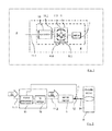
FIG. 1 shows a motor vehicle 2. The motor vehicle 2 includes a motor vehicle actuator 4. The motor vehicle actuator 4 (framed with broken lines) includes a throttle valve 6 and a motor vehicle servomotor arrangement 7. The motor vehicle servomotor arrangement 7 (framed with broken lines) includes a servomotor 8 and a controller 10. The servomotor 8 is realized in the form of a DC motor. The servomotor 8 includes a stator 8.1, a rotor 8.2 and brushes 8.3. The brushes 8.3 contact a shaft 8.4. The controller 10 has a control input 11.1 and a control output 11.2 that is connected to the servomotor 8.
FIG. 2 shows the motor vehicle actuator 4. The motor vehicle actuator 4 is arranged on the throttle valve 6. An output shaft 12 of the servomotor 8 acts upon a throttle valve shaft 14. A position sensor 15 is arranged on the servomotor 8 and connected to the controller 10. The controller 10 includes a microprocessor 16, as well as an H-bridge 18. The microprocessor 16 serves for interpreting the input signals 20 and for calculating the control signal 22 to be converted by the H-bridge.
FIG. 3 shows a first time-position diagram. In this diagram, the input signal 20 is illustrated in the form of a continuous line and the control signal 22 is illustrated in the form of a broken line. The input signal 20 varies between a lower extreme position 24 and an upper extreme position 26, wherein the change between the extreme positions 24 and 26 essentially takes place abruptly in the exemplary embodiment shown. The upper extreme position 26 to be assumed by the servomotor 8 in accordance with the control signal 22 differs by a position differential Δd1 in the two successive cycles shown. The lower extreme positions 24 differ by a position differential Δd2 between the two successive cycles. The position differentials Δd1 and Δd2 are achieved in that the respective extreme position 24, 26 are assumed in one cycle and a different position is assumed in the other cycle. Δd1 and Δd2 may be respectively identical or different. Δd1 and Δd2 may even vary.
FIG. 4 shows a position-opening cross section diagram of the throttle valve 6. The position-opening diagram is essentially sinusoidal and relatively flat in the regions of the extreme positions 24 and 26. A variation of the position of the throttle valve 6 therefore has only a very slight influence on the open cross section of the throttle valve such that this effect is negligible in the driving mode.
FIG. 5 shows the correlation between pressure difference and flow rate in dependence on different opening cross sections A1 to A3. Three different opening cross sections are illustrated in this figure. At small pressure differences, the opening cross section has no significant effect on the flow rate.
While at least one exemplary embodiment has been presented in the foregoing detailed description, it should be appreciated that a vast number of variations exist. It should also be appreciated that the exemplary embodiment or exemplary embodiments are only examples, and are not intended to limit the scope, applicability, or configuration of the invention in any way. Rather, the foregoing detailed description will provide those skilled in the art with a convenient road map for implementing an exemplary embodiment as contemplated herein. It should be understood that various changes may be made in the function and arrangement of elements described in an exemplary embodiment without departing from the scope of the invention as set forth in the appended claims.

Claims (15)

What is claimed is:
1. A motor vehicle servomotor arrangement comprising:
an electric motor having a stator, a rotor and brushes;
a controller having a controller input receiving input signals, a controller output transmitting control signals to the electric motor and a control algorithm executed by the controller to generate an allocated control signal for a given input signal, wherein the allocated control signals are modulated for a given input signal within a predefined input signal range.
2. The motor vehicle servomotor arrangement according to claim 1, wherein the input signal comprises a pulsed-width modulated signal.
3. The motor vehicle servomotor arrangement according to claim 1, wherein the controller comprises an H-bridge.
4. The motor vehicle servomotor arrangement according to claim 1, wherein the electric motor further comprises a position sensor.
5. The motor vehicle servomotor arrangement according to claim 1, wherein the electric motor comprises a DC motor.
6. The motor vehicle actuator comprising an actuator element and a motor vehicle servomotor arrangement according to claim 1 operable to drive the actuator element.
7. A method for operating a motor vehicle servomotor arrangement including an electric motor and a controller, the method comprising:
receiving an input signal on a controller input of the controller;
generating an allocated control signal for a given input signal, wherein the allocated control signals are time-variant for identical successive input signals;
transmitting the allocated control signals from a controller output of the controller to the electric motor in response to the input signal.
8. The method according to claim 7, wherein the at least one predefined input signal range lies in an end section of the input signal spectrum.
9. The method according to claim 7, wherein the at least one predefined input signal range lies in a section of reduced slope of a position-effect diagram of an actuator element driven by the motor vehicle servomotor arrangement.
10. A motor vehicle servomotor arrangement comprising:
an electric motor having a stator, a rotor and brushes;
a controller having a controller input receiving input signals, a controller output transmitting control signals to the electric motor and a control algorithm executed by the controller to generate an allocated control signal to a given input signal, wherein controller modulates the control signals such that time-variant allocated control signals are transmitted for identical input signals.
11. The motor vehicle servomotor arrangement according to claim 10, wherein the input signal comprises a pulsed-width modulated signal.
12. The motor vehicle servomotor arrangement according to claim 10, wherein the controller comprises an H-bridge.
13. The motor vehicle servomotor arrangement according to claim 10, wherein the electric motor further comprises a position sensor.
14. The motor vehicle servomotor arrangement according to claim 10, wherein the electric motor comprises a DC motor.
15. A motor vehicle actuator comprising the motor vehicle servomotor arrangement according to claim 10 and an actuator element operable driven by the motor vehicle servomotor arrangement.
US15/907,306 2017-02-28 2018-02-28 Motor vehicle servomotor arrangement, motor vehicle actuator, motor vehicle and method for operating a motor vehicle servomotor arrangement Active US10439546B2 (en)

Applications Claiming Priority (3)

Application Number Priority Date Filing Date Title
DE102017001896 2017-02-28
DE102017001896.0 2017-02-28
DE102017001896.0A DE102017001896A1 (en) 2017-02-28 2017-02-28 Motor vehicle actuator motor assembly, motor vehicle actuator, motor vehicle, method for operating a Kraftfahrzeugstellmotoranordnung

Publications (2)

Publication Number Publication Date
US20180248506A1 US20180248506A1 (en) 2018-08-30
US10439546B2 true US10439546B2 (en) 2019-10-08

Family

ID=63112228

Family Applications (1)

Application Number Title Priority Date Filing Date
US15/907,306 Active US10439546B2 (en) 2017-02-28 2018-02-28 Motor vehicle servomotor arrangement, motor vehicle actuator, motor vehicle and method for operating a motor vehicle servomotor arrangement

Country Status (3)

Country Link
US (1) US10439546B2 (en)
CN (1) CN108501770A (en)
DE (1) DE102017001896A1 (en)

Families Citing this family (1)

* Cited by examiner, † Cited by third party
Publication number Priority date Publication date Assignee Title
DE102021202587B4 (en) * 2021-03-17 2022-12-08 Audi Aktiengesellschaft Method for operating an actuator for a motor vehicle, corresponding actuator and method for operating an arrangement made up of an actuator and a control unit for a motor vehicle

Citations (1)

* Cited by examiner, † Cited by third party
Publication number Priority date Publication date Assignee Title
US6456030B1 (en) * 1998-09-30 2002-09-24 Hitachi, Ltd. Synchronous motor control device, electric motor vehicle control device and method of controlling synchronous motor

Family Cites Families (6)

* Cited by examiner, † Cited by third party
Publication number Priority date Publication date Assignee Title
DE2732905C3 (en) * 1977-07-21 1994-02-24 Vdo Schindling Device for regulating the driving speed of a motor vehicle
JP2001037294A (en) * 1999-07-22 2001-02-09 Shibaura Densan Kk Motor controller
JP2006191782A (en) * 2004-12-09 2006-07-20 Yamaha Motor Co Ltd Rotating-electric machine
JP2006306190A (en) * 2005-04-27 2006-11-09 Sanyo Electric Co Ltd Force input operating device and mobile body having the same
CN203793560U (en) * 2014-04-04 2014-08-27 太仓市悦博电动科技有限公司 Variable-speed control device for variable-speed electric vehicle
JP6314849B2 (en) * 2015-01-15 2018-04-25 トヨタ自動車株式会社 Vehicle control device

Patent Citations (1)

* Cited by examiner, † Cited by third party
Publication number Priority date Publication date Assignee Title
US6456030B1 (en) * 1998-09-30 2002-09-24 Hitachi, Ltd. Synchronous motor control device, electric motor vehicle control device and method of controlling synchronous motor

Also Published As

Publication number Publication date
US20180248506A1 (en) 2018-08-30
DE102017001896A1 (en) 2018-08-30
CN108501770A (en) 2018-09-07

Similar Documents

Publication Publication Date Title
CN107850232B (en) Control device
US11885412B2 (en) Method of controlling a dog clutch
JPWO2001007768A1 (en) Motor-driven throttle valve control device and control method thereof, automobile, and method for measuring temperature of a throttle valve drive motor for an automobile, and method for measuring temperature of a motor
WO2016008463A1 (en) Method for determining a bite point change and for adapting a friction value of a hybrid separating clutch of a hybrid vehicle
CN102741081A (en) Motor vehicle
WO2019098308A1 (en) Shift range control device
DE112014003376T5 (en) Control device for a vehicle hydraulic pressure supply device
US10439546B2 (en) Motor vehicle servomotor arrangement, motor vehicle actuator, motor vehicle and method for operating a motor vehicle servomotor arrangement
US20110231040A1 (en) Use of discontinuous pulse width modulation for an inverter coupled to an electric motor for a vehicle
CN111356867A (en) gear shifting system
US9000706B2 (en) Actuator control system
CN107846174B (en) Method for gain control of motor based on variable current controller and ECO vehicle
KR20180029469A (en) Method for controlling creep driving of vehicles
KR102542798B1 (en) Method for determining a contact point of a hybrid clutch of a hybrid vehicle
KR20220024806A (en) motor control unit
KR20130045085A (en) Actuator position compecsating method for automated mannual transmission
KR20210097110A (en) Method for determining the beating point of the hybrid separation clutch of a hybrid vehicle
US20180123499A1 (en) Method to reduce electromagnetic interference in switching circuit applications
GB2547678A (en) Method of maintaining a position of an airflow-direction control element of a HVAC system
CN206987970U (en) A kind of pilotless automobile throttle system
CN109070894B (en) Method for operating a drive train of a motor vehicle and drive train module of such a motor vehicle
CN118418753A (en) Method and system for improving the efficiency of an electric machine
US9667185B2 (en) Method and device for operating an electromotive fan drive
US20140000576A1 (en) Chassis mount multi-input h-bridge electrical harness
CN116547610A (en) Apparatus and method for adjusting an electric drive system and electric drive system

Legal Events

Date Code Title Description
FEPP Fee payment procedure

Free format text: ENTITY STATUS SET TO UNDISCOUNTED (ORIGINAL EVENT CODE: BIG.); ENTITY STATUS OF PATENT OWNER: LARGE ENTITY

STPP Information on status: patent application and granting procedure in general

Free format text: NON FINAL ACTION MAILED

STPP Information on status: patent application and granting procedure in general

Free format text: RESPONSE TO NON-FINAL OFFICE ACTION ENTERED AND FORWARDED TO EXAMINER

STPP Information on status: patent application and granting procedure in general

Free format text: NOTICE OF ALLOWANCE MAILED -- APPLICATION RECEIVED IN OFFICE OF PUBLICATIONS

AS Assignment

Owner name: GM GLOBAL TECHNOLOGY OPERATIONS LLC, MICHIGAN

Free format text: ASSIGNMENT OF ASSIGNORS INTEREST;ASSIGNORS:MERZ, ALEXANDER;KLEIN, ALEXANDER;SORRELL, DEAN G.;SIGNING DATES FROM 20180127 TO 20180130;REEL/FRAME:049843/0706

STPP Information on status: patent application and granting procedure in general

Free format text: PUBLICATIONS -- ISSUE FEE PAYMENT VERIFIED

STCF Information on status: patent grant

Free format text: PATENTED CASE

MAFP Maintenance fee payment

Free format text: PAYMENT OF MAINTENANCE FEE, 4TH YEAR, LARGE ENTITY (ORIGINAL EVENT CODE: M1551); ENTITY STATUS OF PATENT OWNER: LARGE ENTITY

Year of fee payment: 4