US104367A - Improvement in crank-motion for engines - Google Patents
Improvement in crank-motion for engines Download PDFInfo
- Publication number
- US104367A US104367A US104367DA US104367A US 104367 A US104367 A US 104367A US 104367D A US104367D A US 104367DA US 104367 A US104367 A US 104367A
- Authority
- US
- United States
- Prior art keywords
- crank
- engines
- motion
- improvement
- shaft
- Prior art date
- Legal status (The legal status is an assumption and is not a legal conclusion. Google has not performed a legal analysis and makes no representation as to the accuracy of the status listed.)
- Expired - Lifetime
Links
Images
Classifications
-
- F—MECHANICAL ENGINEERING; LIGHTING; HEATING; WEAPONS; BLASTING
- F01—MACHINES OR ENGINES IN GENERAL; ENGINE PLANTS IN GENERAL; STEAM ENGINES
- F01L—CYCLICALLY OPERATING VALVES FOR MACHINES OR ENGINES
- F01L1/00—Valve-gear or valve arrangements, e.g. lift-valve gear
- F01L1/12—Transmitting gear between valve drive and valve
- F01L1/18—Rocking arms or levers
- F01L1/181—Centre pivot rocking arms
-
- Y—GENERAL TAGGING OF NEW TECHNOLOGICAL DEVELOPMENTS; GENERAL TAGGING OF CROSS-SECTIONAL TECHNOLOGIES SPANNING OVER SEVERAL SECTIONS OF THE IPC; TECHNICAL SUBJECTS COVERED BY FORMER USPC CROSS-REFERENCE ART COLLECTIONS [XRACs] AND DIGESTS
- Y10—TECHNICAL SUBJECTS COVERED BY FORMER USPC
- Y10T—TECHNICAL SUBJECTS COVERED BY FORMER US CLASSIFICATION
- Y10T74/00—Machine element or mechanism
- Y10T74/20—Control lever and linkage systems
- Y10T74/20576—Elements
- Y10T74/20582—Levers
Definitions
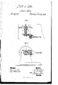
- ⁇ lsignre l represents a horizontalsectionof our improvedcrank-motionj
- Figure 2 is a front elevation, partly in section, of
- This invention relates to certain improvements in that kind of crank-motionsinwhich, by t-he applicationof ⁇ two gear-wheels, themotion of the crank-shaft is doubled.
- the invention consists in mounting the crank upon .a sleeve, which turns loose on the crank-shaft, and f which carries a cam for setting the valve.
- the sleeve which turns loose on the crank-shaft, and f which carries a cam for setting the valve.
- the invention consists also in the use of a novel i ,tion ofthel crank, whosefshatt meanwhile turns A, ⁇ in the drawing, represents theshaft, which is to ⁇ be revolved by the crankB; ⁇
- crank' is mounted upon a tube, C, which is fitted loose around the shaftA, and which carries the eccentric D for operating the valve, by which the mo- E is the connecting-rod for working the crank.
- the wheel F is, by a pin,a, pivoted to the end of the crank, andv carries onehalf of a square projecting box, b.
- This box is tted through the opening formed by a strap, c, inlthe end of the rod E, the other halt ll of the box being put into the same openingto allow adj nstment ot' the strap.
Landscapes
- Engineering & Computer Science (AREA)
- Mechanical Engineering (AREA)
- General Engineering & Computer Science (AREA)
- Transmission Devices (AREA)
- Valve-Gear Or Valve Arrangements (AREA)
Description
` the same.
, tion of the crank isrregulated.
time one.
JOHN entre` AND GODNREY JoI'rHE, or NEWARK, NEW JERSEY.
i ffettcrs Patent No. 104,367., dated June 14,1870.
` "1M-MOVEMENT nv eR-ANRMOTIQN ron ENGINES.
The `Schedule resrred to in` these Letters Patent andv making part of the same `Motion for Engines; and we do hereby declarethat the bllowingis afull, clear, and exact description thereof,
` which will enable others skilled in the art to make and use the same, reference being had to the accomf panying drawingfbrming part ofthis specification, in
`lsignre l represents a horizontalsectionof our improvedcrank-motionj Figure 2 is a front elevation, partly in section, of
, Similar .letters of reference indicate corresponding parts.'
This invention relates to certain improvements in that kind of crank-motionsinwhich, by t-he applicationof` two gear-wheels, themotion of the crank-shaft is doubled.Y
The invention ,consists in mounting the crank upon .a sleeve, which turns loose on the crank-shaft, and f which carries a cam for setting the valve. The sleeve,
cam, andrcrank makey bntfone revolution to two of the shaft, and the valve istherefore set to produce one rotwice'. Y
The invention consists also in the use of a novel i ,tion ofthel crank, whosefshatt meanwhile turns A,` in the drawing, represents theshaft, which is to `be revolved by the crankB;`
The crank'is mounted upon a tube, C, which is fitted loose around the shaftA, and which carries the eccentric D for operating the valve, by which the mo- E is the connecting-rod for working the crank.
The end of this rod is connected Awith a toothedwheel, F, which is hungon the end of the crank.
The wheel F is, by a pin,a, pivoted to the end of the crank, andv carries onehalf of a square projecting box, b. This box is tted through the opening formed by a strap, c, inlthe end of the rod E, the other halt ll of the box being put into the same openingto allow adj nstment ot' the strap. v
By means of' the box b al the wheel will be prevented from turning in the rod, while the pin a allows it to turn on the crank.
Upon the shaft A isvmounted a pinion, G, which meshes into the teeth of the wheel F, receiving, by i the rotation of the .crank and wheel F, two revolutions during every one of the crank. The latter, however, serves to impart but one rotation to the cam D, dnring every two of the shaft A, and the said cam' will, therefore, regulate the motion of the piston inthe same manner in which it would do Yso were the gearing F G not employed.
Having thus described our invention,
'We ela-im as new and desire to secure by Letters Patent--v 1. The sleeve C, cam D', and crank B, in combinac `tion with the shaft A. and toothed-wheels F G, all ar.- ranged to Voperate substantially as herein shown and described. I
2. The block b al, on the toot-hed wheel F, in combination with the pin a, crank B, and eonnecting-rod
Publications (1)
| Publication Number | Publication Date |
|---|---|
| US104367A true US104367A (en) | 1870-06-14 |
Family
ID=2173852
Family Applications (1)
| Application Number | Title | Priority Date | Filing Date |
|---|---|---|---|
| US104367D Expired - Lifetime US104367A (en) | Improvement in crank-motion for engines |
Country Status (1)
| Country | Link |
|---|---|
| US (1) | US104367A (en) |
-
0
- US US104367D patent/US104367A/en not_active Expired - Lifetime
Similar Documents
| Publication | Publication Date | Title |
|---|---|---|
| US104367A (en) | Improvement in crank-motion for engines | |
| US460642A (en) | Variable crank-motion | |
| US421297A (en) | James mills | |
| US1315782A (en) | Power-transmission shaft. | |
| US112603A (en) | Improvement in washing-machines | |
| DE705283C (en) | Internal combustion engine with variable compression space | |
| US100619A (en) | William fiarsen | |
| US1627839A (en) | Steering gear | |
| US1614389A (en) | Pump | |
| US104350A (en) | Improvement in treadle-movements | |
| US119039A (en) | Improvement in steam-engines | |
| US112722A (en) | Improvement in meters | |
| US2763966A (en) | Valve grinding attachment | |
| US86996A (en) | Alexander milles | |
| US1751657A (en) | Operating mechanism for valve grinders | |
| US100483A (en) | woodbury | |
| US111258A (en) | Improvement in mowing-machines | |
| US99052A (en) | George m | |
| US1100278A (en) | Mechanism for totaling the number of revolutions of a rotary body. | |
| DE449127C (en) | Fluid change gearbox | |
| US144747A (en) | Improvement in fluid-meters | |
| DE160126C (en) | ||
| US107331A (en) | Improvement in power-meters | |
| US763131A (en) | Shifting eccentric valve-gear. | |
| US97240A (en) | Fred gardner |