US1043509A - Artificial limb. - Google Patents
Artificial limb. Download PDFInfo
- Publication number
- US1043509A US1043509A US68516212A US1912685162A US1043509A US 1043509 A US1043509 A US 1043509A US 68516212 A US68516212 A US 68516212A US 1912685162 A US1912685162 A US 1912685162A US 1043509 A US1043509 A US 1043509A
- Authority
- US
- United States
- Prior art keywords
- section
- foot
- tubular member
- leg
- artificial limb
- Prior art date
- Legal status (The legal status is an assumption and is not a legal conclusion. Google has not performed a legal analysis and makes no representation as to the accuracy of the status listed.)
- Expired - Lifetime
Links
- 210000002683 foot Anatomy 0.000 description 22
- 210000003414 extremity Anatomy 0.000 description 9
- 210000000544 articulatio talocruralis Anatomy 0.000 description 1
- 238000010276 construction Methods 0.000 description 1
- 210000001503 joint Anatomy 0.000 description 1
- 230000013011 mating Effects 0.000 description 1
- 239000007787 solid Substances 0.000 description 1
Images

Classifications
-
- A—HUMAN NECESSITIES
- A61—MEDICAL OR VETERINARY SCIENCE; HYGIENE
- A61F—FILTERS IMPLANTABLE INTO BLOOD VESSELS; PROSTHESES; DEVICES PROVIDING PATENCY TO, OR PREVENTING COLLAPSING OF, TUBULAR STRUCTURES OF THE BODY, e.g. STENTS; ORTHOPAEDIC, NURSING OR CONTRACEPTIVE DEVICES; FOMENTATION; TREATMENT OR PROTECTION OF EYES OR EARS; BANDAGES, DRESSINGS OR ABSORBENT PADS; FIRST-AID KITS
- A61F2/00—Filters implantable into blood vessels; Prostheses, i.e. artificial substitutes or replacements for parts of the body; Appliances for connecting them with the body; Devices providing patency to, or preventing collapsing of, tubular structures of the body, e.g. stents
- A61F2/50—Prostheses not implantable in the body
- A61F2/60—Artificial legs or feet or parts thereof
- A61F2/66—Feet; Ankle joints
Definitions
- This invention relates to artificial limbs
- the object of the invention resides in the provision of an improved joint for connecting the Foot. member and-leg member of an artificial limb which will be simple in construction, durable, and which affords an efii cient cushion for the weight of the body:
- a further object of the invention resides in the provision of an improved jointbetween the leg section and the foot section of an artificial limb which will readily permit said sections to be separated from each other for repair or replacement of parts.
- the limb comprising a legs'ection A and a net section B, the latter being provided with the usual flexible heel and toe portions and 11 respectively, and a recess 12 in the bottom of its heel portion opening through the flexible portion 10.
- a transverse groove 13 which is connected with the recess 12 by a vertical passage 14.
- the upper end' of the foot section B is provided with a' V-shaped recess 15 forming angular portions 16 and 17 and merging at its inner end into the transverse groove 13.
- the leg section-A is provided at its lower end with a transverse groove 18 which mates with the groove 13 of the foot section B.
- leg section A Rearward of the groove 18 the leg section A is provided with a recess 19 while another recess-2O is formed forward of the groove 18, the angular portions 16 and 17 of the foot section Bbeing adapted to travel in the recesses 19 and 20 respectively when the foot section'is moved relatively to the. leg section during the use of the limb.
- the leg section portion-211M interior of which communicates with the groove 18 by means of vertica1 passages 22 and 23 formed in the solid lower portion of the leg section.
- leg. section A and the-foot section :B is shown as comprising .a
- tubular member 24 is provided centrally with a transverse, slot 25 while the spending points with cut away port-ions 26 and-27 all for a purpose that will presently appear.
- These cores 28 and 29 are held against removal from the tubular member 24 by bolts 31'and 32 which are threaded through the tubular member transversely and through the inner end of said cbres respectively.
- These bolts 31 and 32 are disposed in a common plane passing through the longitudinal axis of the tubular member 24, and extend respectively through the passages 22 and 23 in the leg section A.
- Nuts 33 are threaded on-the upper ends of the bolts 31 and 32 respectively. and serve to positively connect the joint to the leg section.
- a cylindrical block 34 which has anchored therein the inner end A terminates at its. upper end in a tubular
- tubulan member 24 which is seated between formed by the mating grooves 13 and 18.
Landscapes
- Health & Medical Sciences (AREA)
- Transplantation (AREA)
- Biomedical Technology (AREA)
- Cardiology (AREA)
- Oral & Maxillofacial Surgery (AREA)
- Engineering & Computer Science (AREA)
- Orthopedic Medicine & Surgery (AREA)
- Heart & Thoracic Surgery (AREA)
- Vascular Medicine (AREA)
- Life Sciences & Earth Sciences (AREA)
- Animal Behavior & Ethology (AREA)
- General Health & Medical Sciences (AREA)
- Public Health (AREA)
- Veterinary Medicine (AREA)
- Prostheses (AREA)
Description
JJg.c0RnBLL I ARTIFICIAL LIMB.
APPLIUATION FILE D MAR. 21, 1912.
Patented Nbv. 5,1912.
I I 2 SHEETS-SHEET 1.
i?:Eh.L
J. P. CORDELL.
' ARTIFICIAL LIHB.
APPLICATION TILED IAB. 21, 1912..
Patented Nov. 5, 1912.
2 BHEETSBHBET 2.
ier. E
awe/Mom Jifnrde/Z filmin and more par-ticularly to the joint between.
PATENT OFFICE.
JOHN F. GORDELL, F SALTLAKE CITY, UTAHQ ARTIFICIAL LIMB.
Specification of Letters Patent.
Patented Nov. 5, 1912 Salt Lake City, in the county of Salt Lake, State of Utah, have invented certain new and useful Improvements in Artificial Limbs; and I do hereby declare the following to be a full, clear, and exact description of the invention, such-as willenable others skilled in'the art to which it appertains to make and use the same.
This invention relates to artificial limbs,
idle leg member and the foot member of the imb.-- I The object of the invention resides in the provision of an improved joint for connecting the Foot. member and-leg member of an artificial limb which will be simple in construction, durable, and which affords an efii cient cushion for the weight of the body:
when-same'is applied to the 'heela portion of the foot section'ofthe limb.
A further object of the invention resides in the provision of an improved jointbetween the leg section and the foot section of an artificial limb which will readily permit said sections to be separated from each other for repair or replacement of parts.
With the above and other objects in view,
the invention consists in the details of con:
" on the line 3-'-3 O1 Fig.1, Fig. 4, a detail perspective View of the joint removed, and 5, a detail perspective view of the parts of the joint contained within the outer tubular member of said joints.
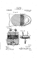
Referring to the drawings the limb is shown comprising a legs'ection A and a net section B, the latter being provided with the usual flexible heel and toe portions and 11 respectively, and a recess 12 in the bottom of its heel portion opening through the flexible portion 10. Formed in the foot section B directly above the recess 12 is a transverse groove 13 which is connected with the recess 12 by a vertical passage 14. The upper end' of the foot section B is provided with a' V-shaped recess 15 forming angular portions 16 and 17 and merging at its inner end into the transverse groove 13. The leg section-A is provided at its lower end with a transverse groove 18 which mates with the groove 13 of the foot section B. Rearward of the groove 18 the leg section A is provided with a recess 19 while another recess-2O is formed forward of the groove 18, the angular portions 16 and 17 of the foot section Bbeing adapted to travel in the recesses 19 and 20 respectively when the foot section'is moved relatively to the. leg section during the use of the limb. The leg section portion-211M interior of which communicates with the groove 18 by means of vertica1=passages 22 and 23 formed in the solid lower portion of the leg section.
The=joint between the leg. section A and the-foot section :B is shown as comprising .a
the leg and foot sections inthe passage This. tubular member 24 is provided centrally with a transverse, slot 25 while the spending points with cut away port-ions 26 and-27 all for a purpose that will presently appear. 1
Disposed within the tubular member 24 at each end' are tubular'cores 28 and 29, each of which have their outer ends reduced as at 30.- These cores 28 and 29 are held against removal from the tubular member 24 by bolts 31'and 32 which are threaded through the tubular member transversely and through the inner end of said cbres respectively. These bolts 31 and 32 are disposed in a common plane passing through the longitudinal axis of the tubular member 24, and extend respectively through the passages 22 and 23 in the leg section A. .Nuts 33 are threaded on-the upper ends of the bolts 31 and 32 respectively. and serve to positively connect the joint to the leg section. Rotatably mounted in the tubular member 24 between the inner ends of the cores 28 and 29 is. a cylindrical block 34 which has anchored therein the inner end A terminates at its. upper end in a tubular,
terminals thereof are provided at correof a bolt which (projects through the slot 25, rotation of sai block 34 being limited by the engagement of the bolt 35 with the ends of the slot 25. This bolt 35 extends through the passage 14 in the foot member .and-has threaded on its outer end a nut 36 through the manipulation of which the foot section is secured to the joint as will be vapparent. Coiled about the reduced portions 30 are the ends of a spring wire 39, the torminals of said endsbeing anchored tov the inner ends of the reduced portions 30 re spectively. The intermediate portion of the springwire 39 is extended laterally of the tu-' bular member 2st in substantially against an edge of thecutaway portion 26 under tension while the other arm. of the lateral extension bears against 8. corresponding edgeof' the cutaway'portion 27 under tension. When'the leg section A andioot section B are connected together by the joint the intermediate U-sha e portion of the spring wire 39 bears agalnst the rearmost side of the recess '15 of the foot section B and constantly tends to move the heel of the foot section Bout of the recess 19 of the leg section. However, in use of the limb when the Weight ofthe body is thrown upon the heel of the U-shape section the U-shape portion of the spring wire 39 will yield so as to cushion the jar that would naturally result if the movement of the heel of the foot section into the recess 19 were unrestrained. The ends of the-tubular member 24 are closed by (3111s 40 and 41 respectively which are secur j in place by means of U-shape and one arm of said lateral extension bears screws $2 threaded into the bores of the cores 28 and 29 respectively.
What is claimed is:
"1. Invan ankle joint, the combination with theJeg" and foot sections of an artificial limb, ofa tubular member disposed between thong and foot sections and non-rotata'bly secured-Ito the former, a cylindrical block 'rotatablymounted in said tubular member and secured to the foot member whereby said foot member is adapted for a limited rotation about the longitudinal axis of said tubularmember and a spring wire having its terminals anchored in the tubular member and its intermediate port-ion directed laterally of the tubular member andengag- 'ing" the rear end of the top of the foot sechinge connection and engaging the rear.
end of the top of the foot section under tension whereby the rear end of the foot section is yieldingly held against mm'ement toward the adjacent portion of the leg section.
In testimony whereof, .I afiix my signature, in presence of two witnesses.
JOHN F. CORDELL. Witnesses:
ORVILLE D. RYAN, Lnv E. SANDERSON.
Priority Applications (1)
| Application Number | Priority Date | Filing Date | Title |
|---|---|---|---|
| US68516212A US1043509A (en) | 1912-03-21 | 1912-03-21 | Artificial limb. |
Applications Claiming Priority (1)
| Application Number | Priority Date | Filing Date | Title |
|---|---|---|---|
| US68516212A US1043509A (en) | 1912-03-21 | 1912-03-21 | Artificial limb. |
Publications (1)
| Publication Number | Publication Date |
|---|---|
| US1043509A true US1043509A (en) | 1912-11-05 |
Family
ID=3111783
Family Applications (1)
| Application Number | Title | Priority Date | Filing Date |
|---|---|---|---|
| US68516212A Expired - Lifetime US1043509A (en) | 1912-03-21 | 1912-03-21 | Artificial limb. |
Country Status (1)
| Country | Link |
|---|---|
| US (1) | US1043509A (en) |
-
1912
- 1912-03-21 US US68516212A patent/US1043509A/en not_active Expired - Lifetime
Similar Documents
| Publication | Publication Date | Title |
|---|---|---|
| US292800A (en) | Artificial leg | |
| US366494A (en) | Artificial leg | |
| US2289154A (en) | Artificial limb | |
| US810180A (en) | Artificial limb. | |
| US470431A (en) | George e | |
| US1090327A (en) | Artificial limb. | |
| US597465A (en) | Artificial leg | |
| US1102774A (en) | Artificial leg. | |
| US668634A (en) | Artificial limb. | |
| US975439A (en) | Artificial limb. | |
| US1368348A (en) | Artificial limb | |
| US961582A (en) | Artificial foot. | |
| US981090A (en) | Artificial foot. | |
| US1350518A (en) | Artificial leg | |
| US1379293A (en) | Artificial leg | |
| US428839A (en) | Artificial limb | |
| US864035A (en) | Artificial limb. | |
| US759753A (en) | Artificial foot. | |
| US567774A (en) | Artificial limb | |
| US1323444A (en) | Artificial leg. | |
| US1244294A (en) | Artificial leg. | |
| US703431A (en) | Artificial limb. | |
| US566684A (en) | Artificial limb | |
| US1008253A (en) | Artificial limb. | |
| US854510A (en) | Artificial foot. |