US10429774B2 - Fixing device having separating member for separating sheet from heating member and image forming apparatus having the same - Google Patents
Fixing device having separating member for separating sheet from heating member and image forming apparatus having the same Download PDFInfo
- Publication number
- US10429774B2 US10429774B2 US15/923,380 US201815923380A US10429774B2 US 10429774 B2 US10429774 B2 US 10429774B2 US 201815923380 A US201815923380 A US 201815923380A US 10429774 B2 US10429774 B2 US 10429774B2
- Authority
- US
- United States
- Prior art keywords
- contact area
- fixing device
- sheet
- separating
- area
- Prior art date
- Legal status (The legal status is an assumption and is not a legal conclusion. Google has not performed a legal analysis and makes no representation as to the accuracy of the status listed.)
- Expired - Fee Related
Links
- 238000010438 heat treatment Methods 0.000 title claims abstract description 85
- 238000005507 spraying Methods 0.000 claims description 4
- 210000000078 claw Anatomy 0.000 description 33
- 239000002184 metal Substances 0.000 description 8
- 238000004140 cleaning Methods 0.000 description 4
- 230000000052 comparative effect Effects 0.000 description 3
- 230000003247 decreasing effect Effects 0.000 description 3
- 230000000694 effects Effects 0.000 description 3
- 229910052736 halogen Inorganic materials 0.000 description 3
- 150000002367 halogens Chemical class 0.000 description 3
- 238000000034 method Methods 0.000 description 3
- 230000008901 benefit Effects 0.000 description 2
- 238000005299 abrasion Methods 0.000 description 1
- 229920001577 copolymer Polymers 0.000 description 1
- RTZKZFJDLAIYFH-UHFFFAOYSA-N ether Substances CCOCC RTZKZFJDLAIYFH-UHFFFAOYSA-N 0.000 description 1
- 238000010348 incorporation Methods 0.000 description 1
- 239000000463 material Substances 0.000 description 1
- 239000000126 substance Substances 0.000 description 1
- BFKJFAAPBSQJPD-UHFFFAOYSA-N tetrafluoroethene Chemical group FC(F)=C(F)F BFKJFAAPBSQJPD-UHFFFAOYSA-N 0.000 description 1
Images


Classifications
-
- G—PHYSICS
- G03—PHOTOGRAPHY; CINEMATOGRAPHY; ANALOGOUS TECHNIQUES USING WAVES OTHER THAN OPTICAL WAVES; ELECTROGRAPHY; HOLOGRAPHY
- G03G—ELECTROGRAPHY; ELECTROPHOTOGRAPHY; MAGNETOGRAPHY
- G03G15/00—Apparatus for electrographic processes using a charge pattern
- G03G15/20—Apparatus for electrographic processes using a charge pattern for fixing, e.g. by using heat
- G03G15/2003—Apparatus for electrographic processes using a charge pattern for fixing, e.g. by using heat using heat
- G03G15/2014—Apparatus for electrographic processes using a charge pattern for fixing, e.g. by using heat using heat using contact heat
- G03G15/2017—Structural details of the fixing unit in general, e.g. cooling means, heat shielding means
- G03G15/2028—Structural details of the fixing unit in general, e.g. cooling means, heat shielding means with means for handling the copy material in the fixing nip, e.g. introduction guides, stripping means
-
- G—PHYSICS
- G03—PHOTOGRAPHY; CINEMATOGRAPHY; ANALOGOUS TECHNIQUES USING WAVES OTHER THAN OPTICAL WAVES; ELECTROGRAPHY; HOLOGRAPHY
- G03G—ELECTROGRAPHY; ELECTROPHOTOGRAPHY; MAGNETOGRAPHY
- G03G15/00—Apparatus for electrographic processes using a charge pattern
- G03G15/20—Apparatus for electrographic processes using a charge pattern for fixing, e.g. by using heat
- G03G15/2003—Apparatus for electrographic processes using a charge pattern for fixing, e.g. by using heat using heat
- G03G15/2014—Apparatus for electrographic processes using a charge pattern for fixing, e.g. by using heat using heat using contact heat
- G03G15/2053—Structural details of heat elements, e.g. structure of roller or belt, eddy current, induction heating
Definitions
- the present disclosure relates to a fixing device fixing a toner image on a sheet and an image forming apparatus including the fixing device.
- An image forming apparatus is provided with a fixing device which heats and presses a toner image transferred on a sheet and fixes the toner image on the sheet.
- the fixing device includes a rotatable heating member heated by a heat source and a pressing member being pressed against the heating member to form a pressing area between the heating member and the pressing member. When the sheet on which the toner image is transferred passes through the pressing area, the toner image is heated and pressed to be fixed on the sheet.
- the fixing device further includes a separating member which comes into contact with the heating member and separates the sheet passed through the pressing area from the heating member.
- the separating member comes into contact with the heating member, a fine offset toner adhered on a surface of the heating member is fused on the separating member, and then the heating member is scraped by the fused toner of the separating member. If a depth of the scraped portion increases, an image having white streak may be printed before the end of the lifetime of the fixing device.
- a contact pressure between the separating member and the heating member is decreased, a separating failure for a specific sheet may occur.
- the separating member reciprocates in an axis direction of the heating member to distribute the contact position between the separating member and the heating member, although some degree of effect can be obtained, it is difficult to keep the effect until the end of the lifetime of the fixing device.
- a hard intermediate layer may be sometimes provided between a release layer and a primer layer of the heating member along a circumferential direction of the heating member.
- a cleaning member may be provided, which comes into contact with the non-contact portion where the separating claw (the separating member) does not come into contact with the heating member and collects the adhered substance produced by the fine offset toner.
- the intermediate layer when the intermediate layer is provided, the producing process for the heating member becomes complicate. In addition, the intermediate layer does not offer the effect for decreasing the abrasion of the release layer.
- the cleaning member when it is required to add a new member, a cost may be increased and a control process for the cleaning member may be complicate. In addition, the cleaning performance may be decreased before the end of the lifetime of the fixing device.
- a fixing device includes a heating member, a pressing member and a separating member.
- the heating member heats a toner transferred on a sheet.
- the pressing member forms a pressing area with the heating member.
- the toner is pressed at the pressing area.
- the separating member comes into contact with an outer circumferential face of the heating member and separates the sheet passed through the pressing area from the heating member.
- the heating member has a contact area with which the separating member comes into contact and a non-contact area with which the separating member does not come into contact.
- the heating member has a larger outer diameter at the contact area than an outer diameter at the non-contact area.
- an image forming apparatus includes an image forming part and the fixing device.
- the image forming part forms a toner image on a sheet.
- the fixing device fixes the toner image on the sheet.
- FIG. 1 is a front view schematically showing an inner structure of a printer according to one embodiment of the present disclosure.
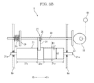
- FIG. 2 is a sectional view showing a fixing device according to the embodiment of the present disclosure.
- FIGS. 3A and 3B are side views showing the fixing device according to the embodiment of the present disclosure.
- FIG. 4 is a sectional view showing a heating roller at an initial state and after a durability test, in a fixing device according to a comparative embodiment.
- FIG. 5 is a sectional view showing a heating roller at an initial state and after a durability test, in the fixing device according to the embodiment of the present disclosure.
- FIG. 1 is a font view schematically showing an inner structure of the printer 1 .
- a near side (a front side) of a paper plan of FIG. 1 is decided to be a front side of the printer 1 .
- Fr, Rr, L and R respectively indicate a front side, a rear side, a left side and a right side.
- An apparatus main body 2 of the printer 1 is provided with a sheet feeding cassette 3 storing a sheet S, a sheet feeding device 4 feeding the sheet S from the sheet feeding cassette 3 , an image forming part 5 forming a toner image on the sheet S, a fixing device 6 fixing the toner image on the sheet S, an ejecting device 7 ejecting the sheet S and an ejected sheet tray 8 on which the ejected sheet S is stacked.
- a conveying path 10 for the sheet S is formed so as to extend from the sheet feeding device 4 to the ejecting device 7 through the image forming part 5 and the fixing device 6 .
- the sheet S is fed by the sheet feeding device 4 from the sheet feeding cassette 3 , and conveyed along the conveying path 10 to the image forming part 5 .
- the toner image is formed on the sheet S.
- the sheet S is conveyed along the conveying path 10 to the fixing device 6 .
- the fixing device 6 fixes the toner image on the sheet S.
- the sheet S on which the toner image is fixed is ejected from the ejecting device 7 , and then stacked on the ejected sheet tray 8 .
- FIG. 2 is a sectional view showing the fixing device 6 and FIGS. 3A and 3B are side views showing the fixing device 6 .
- FIGS. 3A and 3B schematically show a positional relationship between a separating member 27 and a heating roller 21 .
- the fixing device 6 includes a heating roller 21 as a heating member heating the toner, a halogen heater 23 heating the heating roller 21 , a pressing roller 25 being pressed against the heating roller 21 from the lower side and forming a pressing area N where the toner is pressed and a separating member 27 which comes into contact with the heating roller 21 and separates the sheet S passing through the pressing area N from the heating roller 21 .
- the heating roller 21 includes a cylindrical core metal 21 a and a release layer 21 c provided around an outer circumferential face of the core metal 21 a via a primer layer 21 b .
- the release layer 21 c is made of tetrafluoroethylene/perfluoroalkylvinyl ether copolymer (PFA).
- PFA tetrafluoroethylene/perfluoroalkylvinyl ether copolymer
- the heating roller 21 is made so as to have a larger outer diameter R 1 at a center portion (hereinafter, called as a contact area 21 x ) in an axis direction of the core metal 21 a than an outer diameter R 2 at other portion (hereinafter, called as a non-contact area 21 y ) excepting the contact area 21 x .
- the core metal 21 a and the primer layer 21 b each have a constant thickness in the axis direction while the release layer 21 c has a larger thickness at the contact area 21 x than a thickness at the non-contact area 21 y .
- a length of the contact area 21 x in the axis direction is 7 mm
- a difference T between a radius (R 1 / 2 ) of the heating roller 21 at the contact area 21 x and a radius (R 2 / 2 ) of the heating roller 21 at the non-contact area 21 y is 5 ⁇ m to 8 ⁇ m.
- the release layer 21 c is made by the following manner, for example.
- the release layer is made by a spray coating method.
- a nozzle is moved from one end to the other end of an outer circumferential face of the primer layer in the axis direction at a constant feed rate.
- the release layer is made to have a constant thickness in the axis direction.
- the feed rate of the nozzle is made slower at the contact area 21 x than at the non-contact area 21 y so that an amount of a material sprayed from the nozzle is larger at the contact area 21 x than at the non-contact area 21 y , and the release layer 21 c has a thicker thickness at the contact area 21 x than a thickness at the non-contact area 21 y .
- the release layer 21 c may be made by another method.
- the halogen heater 23 is disposed in an inside of the core metal 21 a of the heating roller 21 .
- the halogen heater 23 radiates radiant heat to an inner circumferential face of the heating roller 21 to heat the heating roller 21 .
- the pressing roller 22 includes a rotating shaft, an elastic layer provided around the rotating shaft and a release layer provided around the elastic layer.
- the pressing roller 25 is rotatably supported by the fixing housing and pressed against the heating roller 21 from the lower side. Thereby, the pressing area N is formed between the pressing roller 25 and the heating roller 21 .
- the separating member 27 includes a separating claw 31 , an operating shaft 33 supporting the separating claw 31 and a torsion coil spring 35 disposed between the separating claw 31 and the operating shaft 33 .
- the separating claw 31 is a triangular member, viewed from the side, having a sharp tip end, as shown in FIG. 2 .
- a length (a width) of the separating claw 31 in the axis direction is 3 mm, for example.
- a pressed plate 37 is fixed to a front end of the operating shaft 33
- a stopper plate 39 is fixed to a rear end portion of the operating shaft 33 .
- the separating claw 31 is rotatably supported by the operating shaft 33 almost at a center between the pressed plate 37 and the stopper plate 39 .
- the torsion coil spring 35 has a coil part and two arm parts. An angle between the two arm parts is 90 degree at an unloaded state.
- the coil part is disposed around the operating shaft 33 , one of the arm parts is fixed to the operating shaft 33 and the other of the arm parts is fixed to the separating claw 31 .
- the torsion coil spring 35 biases the separating claw 31 with respect to the operating shaft 33 in the counterclockwise direction in FIG. 2 .
- the separating member 27 is disposed at the downstream side of the pressing area N in the conveying direction.
- the operating shaft 33 is supported by the fixing housing in a parallel posture with the core metal 21 a of the heating roller 21 and is movable in the axis direction, as described later.
- the separating claw 31 is pressed against the heating roller 21 at the contact area 21 x by biasing force of the torsion coil spring 35 from a counter direction to a rotating direction of the heating roller 21 .
- a front end portion (a portion at the rear side of the pressed plate 37 ) of the operating shaft 33 and the rear end portion (a portion at the rear side of the stopper plate 39 ) are rotatably supported by a front side plate 6 a and a rear side plate 6 b of the fixing housing, respectively.
- a cam 53 rotating around an axis perpendicular to the axis direction of the operating shaft 33 is disposed at the front side of the pressed plate 37 .
- a spring 55 is disposed between the stopper plate 39 and the rear side plate 6 b . The spring 55 biases the stopper plate 39 , that is, the operating shaft 33 forward with respect to the rear side plate 6 b to make the pressed plate 37 come into contact with the cam 53 .
- the pressed plate 37 is pressed in the axis direction by rotating of the cam 53 and biasing force of the spring 55 so that the operating shaft 33 reciprocates in the axis direction.
- the separating claw 31 reciprocates within a predetermined area while coming into contact with the heating roller 21 .
- the reciprocating area of the separating claw 31 (an area between an outer side edge of the separating claw 31 when the separating claw 31 is moved in one direction and the other outer side edge of the separating claw 31 when the separating claw 31 is moved in the other direction) is made to be matched with the contact area 21 x .
- the reciprocating area of the separating claw 31 may be wider than the contact area 21 x if the separating claw 31 necessarily comes in contact with the heating roller 21 at the contact area 21 x when the separating claw 31 reciprocates in the one direction and the other direction.
- the fixing device 6 having the above configuration, when the heating roller 21 is driven to be rotated, the pressing roller 25 pressed against the heating roller 21 at the pressing area N is driven to be rotated, and the sheet S is passed through the pressing area N. At the pressing area N, the toner image transferred on the sheet S is heated and pressed to be fixed on the sheet S. The sheet S on which the toner image is fixed is conveyed along the conveying path 10 from the pressing area N. At this time, the sheet S is separated from the heating roller 21 by the separating claw 31 of the separating member 27 .
- a drive motor 61 for driving the cam 53 is driven, and the separating claw 31 of the separating member 27 reciprocates in the axis direction (a direction perpendicular to the conveying direction for the sheet S) within the contact area 21 x (the reciprocating area).
- the reciprocating area of the separating claw 31 is matched with the contact area 21 x , the separating claw 31 can reciprocate smoothly without being caught by side edges of the contact area 21 x.
- the release layer 21 c is gradually worn by coming into contact with the sheet S.
- the release layer 21 c is further worn at the contact area 21 x by coming into contact with the separating claw 31 reciprocating within the contact area 21 x . That is, the release layer 21 c at the contact area 21 x is worn faster than the release layer 21 c at the non-contact area 21 y .
- the release layer 21 c has a larger outer diameter at the contact area 21 x than at the non-contact area 21 y , an absolute difference in height between the outer circumferential face of the release layer 21 c at the contact area 21 x after the wear by the separating claw 31 and the outer circumferential face of the release layer 21 c at the non-contact area 21 y is reduced after a predetermined fixing operation. That is, a depth of a recess produced by the wear can be made shallow.
- FIG. 4 is a sectional view showing the worn release layer in a comparative embodiment
- FIG. 5 is a sectional view showing the worn release layer in the present embodiment.
- Each left figure in FIG. 4 and FIG. 5 shows the release layer at an initial state and each right figure in FIG. 4 and FIG. 5 shows the release layer after a durability test.
- the conventional fixing device which includes the heating roller 21 having the release layer 21 c of a constant thickness
- the conventional fixing device is attached to an experimental machine, and a durability test for printing 300K of the sheets S (300,000 sheets S) is carried out.
- a durability test for printing 300K of the sheets S 300,000 sheets S
- a depth D 1 of the worn portion is 2 ⁇ m.
- the release layer 21 c is worn with respect to the initial outer circumferential face by coming into contact with the sheet and the separating claw 31 .
- the depth D 2 of the worn portion is 10 ⁇ m.
- an annular recess G is formed in the heating roller 21 . That is, a depth D 3 of the recess G with respect to a reference face after the durability test (the outer circumferential face after the wear by coming into contact with the sheet) is 8 ⁇ m.
- a depth D 3 of the recess G with respect to a reference face after the durability test is 8 ⁇ m.
- the fixing device when a half image is printed, an image having white streak is printed at the reciprocating area.
- the fixing device 6 which includes the heating roller 21 which has a larger radius at the contact area 21 x than a radius at the non-contact area 21 y by 5 ⁇ m is attached to the experimental machine, and the durability test for printing 300K of the sheets S (300,000 sheets S) is carried out.
- the durability test for printing 300K of the sheets S 300,000 sheets S
- FIG. 5 an entire area of the release layer 21 c is worn with respect to the initial outer circumferential face by coming into contact with the sheet S.
- the depth D 1 of the worn portion (the scraped depth) is 2 ⁇ m.
- the release layer 21 c is worn with respect to the initial outer circumferential face by coming into contact with the sheet and the separating claw 31 .
- the depth D 2 of the worn portion is 10 ⁇ m.
- an annular recess G is formed in the heating roller 21 . That is, a depth D 3 of the recess G with respect to a reference face after the durability test (the outer circumferential face after the wear by the coming into contact with the sheet) is 3 ⁇ m.
- the fixing device 6 when the half image is printed, an image having no white streak is printed at the contact area 21 x.
- the depth of the recess G with respect to the reference face after the durability test is 6 ⁇ m. An image having no white streak is printed at the half image printing.
- the heating roller 21 has a larger outer diameter at the contact area 21 x where the wear proceeds rapidly than an outer diameter at the non-contact area 21 y .
- a difference between the radius (R 1 / 2 ) of the heating roller 21 at the contact area 21 x and the radius (R 2 / 2 ) of the heating roller 21 at the non-contact area 21 y is set to be 5 ⁇ m to 8 ⁇ m. This prevents the image having white streak at the initial state.
- the release layer 21 c is formed on the outer circumferential face of the heating roller 21 , it becomes possible to separate the sheet from the heating roller 21 suitably. If the release layer 21 c may be made by the spray coating method, it becomes possible to make the heating roller 21 having a larger outer diameter at the contact area 21 x than that at the non-contact area 21 y by a simple way where the feeding rate of the nozzle is made lower at the contact area 21 x than at the non-contact area 21 y.
- the separating claw 31 reciprocates to distribute the contact position between the separating claw 31 and the heating roller 21 , it becomes possible to reduce the local wear of the heating roller 21 .
- the present disclosure can be applied to the fixing device in which the separating claw 31 does not reciprocate.
Landscapes
- Physics & Mathematics (AREA)
- General Physics & Mathematics (AREA)
- Fixing For Electrophotography (AREA)
Abstract
Description
Claims (7)
Applications Claiming Priority (2)
| Application Number | Priority Date | Filing Date | Title |
|---|---|---|---|
| JP2017094139A JP6787247B2 (en) | 2017-05-10 | 2017-05-10 | Fixing device and image forming device |
| JP2017-094139 | 2017-05-10 |
Publications (2)
| Publication Number | Publication Date |
|---|---|
| US20180329343A1 US20180329343A1 (en) | 2018-11-15 |
| US10429774B2 true US10429774B2 (en) | 2019-10-01 |
Family
ID=64096309
Family Applications (1)
| Application Number | Title | Priority Date | Filing Date |
|---|---|---|---|
| US15/923,380 Expired - Fee Related US10429774B2 (en) | 2017-05-10 | 2018-03-16 | Fixing device having separating member for separating sheet from heating member and image forming apparatus having the same |
Country Status (2)
| Country | Link |
|---|---|
| US (1) | US10429774B2 (en) |
| JP (1) | JP6787247B2 (en) |
Citations (4)
| Publication number | Priority date | Publication date | Assignee | Title |
|---|---|---|---|---|
| US5956555A (en) * | 1998-07-27 | 1999-09-21 | Eastman Kodak Company | Fusing belt having polyurethane release layer |
| US20020098018A1 (en) * | 1999-03-09 | 2002-07-25 | Yuji Kamiya | Fixing device having an intruding separation member |
| JP2004125942A (en) | 2002-09-30 | 2004-04-22 | Ricoh Co Ltd | Heat fixing roller and heat fixing device having the same |
| JP2013011687A (en) | 2011-06-28 | 2013-01-17 | Ricoh Co Ltd | Fixing device, and image forming apparatus |
Family Cites Families (2)
| Publication number | Priority date | Publication date | Assignee | Title |
|---|---|---|---|---|
| JPS60104985A (en) * | 1983-11-14 | 1985-06-10 | Fuji Xerox Co Ltd | Fixing device |
| DE102005030963B4 (en) * | 2005-06-30 | 2007-07-19 | Daimlerchrysler Ag | Method and device for confirming and / or correcting a speech input supplied to a speech recognition system |
-
2017
- 2017-05-10 JP JP2017094139A patent/JP6787247B2/en not_active Expired - Fee Related
-
2018
- 2018-03-16 US US15/923,380 patent/US10429774B2/en not_active Expired - Fee Related
Patent Citations (5)
| Publication number | Priority date | Publication date | Assignee | Title |
|---|---|---|---|---|
| US5956555A (en) * | 1998-07-27 | 1999-09-21 | Eastman Kodak Company | Fusing belt having polyurethane release layer |
| US20020098018A1 (en) * | 1999-03-09 | 2002-07-25 | Yuji Kamiya | Fixing device having an intruding separation member |
| JP2004125942A (en) | 2002-09-30 | 2004-04-22 | Ricoh Co Ltd | Heat fixing roller and heat fixing device having the same |
| JP2013011687A (en) | 2011-06-28 | 2013-01-17 | Ricoh Co Ltd | Fixing device, and image forming apparatus |
| US8989641B2 (en) | 2011-06-28 | 2015-03-24 | Ricoh Company, Ltd. | Fixing device with mechanism capable of minimizing glossy streaks and stain on recording medium and image forming apparatus incorporating same |
Also Published As
| Publication number | Publication date |
|---|---|
| US20180329343A1 (en) | 2018-11-15 |
| JP6787247B2 (en) | 2020-11-18 |
| JP2018189893A (en) | 2018-11-29 |
Similar Documents
| Publication | Publication Date | Title |
|---|---|---|
| US10901353B2 (en) | Fuser with an endless belt, image forming apparatus with an endless belt, and conveyer with an endless belt | |
| JP6493891B2 (en) | Fixing device | |
| US9939761B2 (en) | Fixing device and image forming apparatus that include a separation aid disposed downstream from the fixing nip | |
| US8706014B2 (en) | Fixing unit and image forming apparatus reducing occurrence of wrinkles on recording medium | |
| JP6493743B2 (en) | Fixing apparatus and image forming apparatus | |
| US20160259282A1 (en) | Fixing device and image forming apparatus | |
| CN107966890A (en) | Image heating equipment | |
| US8831492B2 (en) | Image heating apparatus | |
| US10429774B2 (en) | Fixing device having separating member for separating sheet from heating member and image forming apparatus having the same | |
| US9696668B2 (en) | Fixing device and image forming apparatus | |
| JP6271863B2 (en) | Fixing apparatus and image forming apparatus | |
| CN108732897A (en) | Fixing device | |
| JP6697713B2 (en) | Fixing device and image forming apparatus | |
| JP6406286B2 (en) | Fixing apparatus and image forming apparatus having the same | |
| JP6576178B2 (en) | Recording device | |
| JP6493742B2 (en) | Fixing apparatus and image forming apparatus | |
| JP6699617B2 (en) | Fixing device and image forming apparatus | |
| CN110347028B (en) | Fixing device and image forming apparatus | |
| JP7066460B2 (en) | Fixing device | |
| JP6708811B2 (en) | Liquid ejecting apparatus and image forming apparatus | |
| US10613456B2 (en) | Guide member downstream of a fixing device and image forming apparatus having the same | |
| JP2013103234A (en) | Cylindrical shaft and method for manufacturing cylindrical shaft | |
| JP6722330B2 (en) | Recording device, control method and program | |
| JP2008281893A (en) | Manufacturing method of fixing device and fixing device of image forming apparatus | |
| JP7087463B2 (en) | Fixing device and image forming device |
Legal Events
| Date | Code | Title | Description |
|---|---|---|---|
| AS | Assignment |
Owner name: KYOCERA DOCUMENT SOLUTIONS INC, JAPAN Free format text: ASSIGNMENT OF ASSIGNORS INTEREST;ASSIGNOR:OKINAKA, KENTARO;REEL/FRAME:045254/0895 Effective date: 20180308 |
|
| FEPP | Fee payment procedure |
Free format text: ENTITY STATUS SET TO UNDISCOUNTED (ORIGINAL EVENT CODE: BIG.); ENTITY STATUS OF PATENT OWNER: LARGE ENTITY |
|
| STPP | Information on status: patent application and granting procedure in general |
Free format text: NON FINAL ACTION MAILED |
|
| STPP | Information on status: patent application and granting procedure in general |
Free format text: RESPONSE TO NON-FINAL OFFICE ACTION ENTERED AND FORWARDED TO EXAMINER |
|
| STPP | Information on status: patent application and granting procedure in general |
Free format text: FINAL REJECTION MAILED |
|
| STPP | Information on status: patent application and granting procedure in general |
Free format text: NOTICE OF ALLOWANCE MAILED -- APPLICATION RECEIVED IN OFFICE OF PUBLICATIONS |
|
| STPP | Information on status: patent application and granting procedure in general |
Free format text: PUBLICATIONS -- ISSUE FEE PAYMENT RECEIVED |
|
| STCF | Information on status: patent grant |
Free format text: PATENTED CASE |
|
| FEPP | Fee payment procedure |
Free format text: MAINTENANCE FEE REMINDER MAILED (ORIGINAL EVENT CODE: REM.); ENTITY STATUS OF PATENT OWNER: LARGE ENTITY |
|
| LAPS | Lapse for failure to pay maintenance fees |
Free format text: PATENT EXPIRED FOR FAILURE TO PAY MAINTENANCE FEES (ORIGINAL EVENT CODE: EXP.); ENTITY STATUS OF PATENT OWNER: LARGE ENTITY |
|
| STCH | Information on status: patent discontinuation |
Free format text: PATENT EXPIRED DUE TO NONPAYMENT OF MAINTENANCE FEES UNDER 37 CFR 1.362 |
|
| FP | Lapsed due to failure to pay maintenance fee |
Effective date: 20231001 |