US10425036B2 - Photovoltaic data collection device - Google Patents
Photovoltaic data collection device Download PDFInfo
- Publication number
- US10425036B2 US10425036B2 US14/989,719 US201614989719A US10425036B2 US 10425036 B2 US10425036 B2 US 10425036B2 US 201614989719 A US201614989719 A US 201614989719A US 10425036 B2 US10425036 B2 US 10425036B2
- Authority
- US
- United States
- Prior art keywords
- power generation
- pattern
- photovoltaic
- graph
- data
- Prior art date
- Legal status (The legal status is an assumption and is not a legal conclusion. Google has not performed a legal analysis and makes no representation as to the accuracy of the status listed.)
- Expired - Fee Related, expires
Links
- 238000013480 data collection Methods 0.000 title claims abstract description 43
- 238000010248 power generation Methods 0.000 claims abstract description 166
- 238000012544 monitoring process Methods 0.000 claims abstract description 39
- 239000000284 extract Substances 0.000 abstract 1
- 238000004146 energy storage Methods 0.000 description 37
- 238000000034 method Methods 0.000 description 14
- 238000010586 diagram Methods 0.000 description 13
- 238000004891 communication Methods 0.000 description 10
- 230000005611 electricity Effects 0.000 description 7
- 230000005540 biological transmission Effects 0.000 description 6
- 230000007423 decrease Effects 0.000 description 5
- 230000008901 benefit Effects 0.000 description 3
- 230000008878 coupling Effects 0.000 description 2
- 238000010168 coupling process Methods 0.000 description 2
- 238000005859 coupling reaction Methods 0.000 description 2
- 230000002354 daily effect Effects 0.000 description 2
- 238000013461 design Methods 0.000 description 2
- 238000007599 discharging Methods 0.000 description 2
- 230000000694 effects Effects 0.000 description 2
- 239000013589 supplement Substances 0.000 description 2
- 238000003915 air pollution Methods 0.000 description 1
- 230000003247 decreasing effect Effects 0.000 description 1
- 238000003912 environmental pollution Methods 0.000 description 1
- 230000003203 everyday effect Effects 0.000 description 1
- 239000000446 fuel Substances 0.000 description 1
- 230000007774 longterm Effects 0.000 description 1
- 230000007257 malfunction Effects 0.000 description 1
- 239000002699 waste material Substances 0.000 description 1
Images


Classifications
-
- H—ELECTRICITY
- H02—GENERATION; CONVERSION OR DISTRIBUTION OF ELECTRIC POWER
- H02S—GENERATION OF ELECTRIC POWER BY CONVERSION OF INFRARED RADIATION, VISIBLE LIGHT OR ULTRAVIOLET LIGHT, e.g. USING PHOTOVOLTAIC [PV] MODULES
- H02S50/00—Monitoring or testing of PV systems, e.g. load balancing or fault identification
-
- H—ELECTRICITY
- H02—GENERATION; CONVERSION OR DISTRIBUTION OF ELECTRIC POWER
- H02J—CIRCUIT ARRANGEMENTS OR SYSTEMS FOR SUPPLYING OR DISTRIBUTING ELECTRIC POWER; SYSTEMS FOR STORING ELECTRIC ENERGY
- H02J7/00—Circuit arrangements for charging or depolarising batteries or for supplying loads from batteries
- H02J7/34—Parallel operation in networks using both storage and other DC sources, e.g. providing buffering
- H02J7/35—Parallel operation in networks using both storage and other DC sources, e.g. providing buffering with light sensitive cells
-
- H—ELECTRICITY
- H02—GENERATION; CONVERSION OR DISTRIBUTION OF ELECTRIC POWER
- H02S—GENERATION OF ELECTRIC POWER BY CONVERSION OF INFRARED RADIATION, VISIBLE LIGHT OR ULTRAVIOLET LIGHT, e.g. USING PHOTOVOLTAIC [PV] MODULES
- H02S40/00—Components or accessories in combination with PV modules, not provided for in groups H02S10/00 - H02S30/00
- H02S40/30—Electrical components
- H02S40/32—Electrical components comprising DC/AC inverter means associated with the PV module itself, e.g. AC modules
-
- H—ELECTRICITY
- H02—GENERATION; CONVERSION OR DISTRIBUTION OF ELECTRIC POWER
- H02S—GENERATION OF ELECTRIC POWER BY CONVERSION OF INFRARED RADIATION, VISIBLE LIGHT OR ULTRAVIOLET LIGHT, e.g. USING PHOTOVOLTAIC [PV] MODULES
- H02S40/00—Components or accessories in combination with PV modules, not provided for in groups H02S10/00 - H02S30/00
- H02S40/30—Electrical components
- H02S40/34—Electrical components comprising specially adapted electrical connection means to be structurally associated with the PV module, e.g. junction boxes
-
- H—ELECTRICITY
- H10—SEMICONDUCTOR DEVICES; ELECTRIC SOLID-STATE DEVICES NOT OTHERWISE PROVIDED FOR
- H10F—INORGANIC SEMICONDUCTOR DEVICES SENSITIVE TO INFRARED RADIATION, LIGHT, ELECTROMAGNETIC RADIATION OF SHORTER WAVELENGTH OR CORPUSCULAR RADIATION
- H10F77/00—Constructional details of devices covered by this subclass
- H10F77/90—Energy storage means directly associated or integrated with photovoltaic cells, e.g. capacitors integrated with photovoltaic cells
-
- Y—GENERAL TAGGING OF NEW TECHNOLOGICAL DEVELOPMENTS; GENERAL TAGGING OF CROSS-SECTIONAL TECHNOLOGIES SPANNING OVER SEVERAL SECTIONS OF THE IPC; TECHNICAL SUBJECTS COVERED BY FORMER USPC CROSS-REFERENCE ART COLLECTIONS [XRACs] AND DIGESTS
- Y02—TECHNOLOGIES OR APPLICATIONS FOR MITIGATION OR ADAPTATION AGAINST CLIMATE CHANGE
- Y02E—REDUCTION OF GREENHOUSE GAS [GHG] EMISSIONS, RELATED TO ENERGY GENERATION, TRANSMISSION OR DISTRIBUTION
- Y02E10/00—Energy generation through renewable energy sources
- Y02E10/50—Photovoltaic [PV] energy
- Y02E10/56—Power conversion systems, e.g. maximum power point trackers
Definitions
- the present disclosure relates to a photovoltaic device, and particularly to, a device that monitors a photovoltaic power generation result value.
- photovoltaic power generation that uses solar energy to produce electricity on a large scale by spreading, on a large scale, panels to which solar batteries are attached.
- the photovoltaic power generation has advantages in that there is no need to consume fuel costs and there is no air pollution or waste, because it uses unlimited, pollution-free solar energy.
- a solar energy power generation style includes an independent style and a system-associated style.
- a photovoltaic device is connected to a typical power system.
- a photovoltaic system When a photovoltaic system generates electricity in daytime, it transmits power and at night or when it rains, the photovoltaic power generation system receives electricity from a system.
- a photovoltaic system In order to efficiently use the system-associated photovoltaic system, a photovoltaic system has been introduced which stores idle power in a battery energy storage system (BESS) under a light load, and discharges the BESS to supply discharged power as well as photovoltaic power to the system under a heavy load.
- BESS battery energy storage system
- Embodiments provide a photovoltaic device that delivers minimum data for making a graph to increase monitoring efficiency under the assumption that a daily power generation amount graph of photovoltaic power generation has a certain pattern.
- a data collection device for photovoltaic power generation includes a receiver receiving data on an amount of photovoltaic power generation; a storage unit storing a representative pattern of a graph for monitoring the amount of photovoltaic power generation; a control unit making a graph for monitoring the amount of photovoltaic power generation based on a first piece of data on the amount of photovoltaic power generation received by the receiver and the representative pattern stored in the storage unit; and a transmitter transmitting the graph made by the control unit to an external device.
- the control unit may compare the first piece of data with the representative pattern, select a most similar representative pattern as a result of comparison, and make a graph.
- the control unit may make a graph based on a graph pattern selected when recently making a graph, when as a result of comparison, a selectable representative pattern is in plurality.
- the receiver may further receive a second piece of data on photovoltaic power generation, and
- the second piece of data may include an exceptional section start time, an exceptional section end time, and a minimum amount of power generation within an exceptional section.
- the control unit may compare the second piece of data with a second representative pattern stored in the storage unit ( 317 ) to modify an entire graph.
- the control unit may receive power generation amount data on all exceptional sections to make the entire graph, when the second piece of data is in plurality.
- the first piece of data may include a time at which power generation starts, a time at which power generation ends, and a maximum amount of power generation.
- a photovoltaic system in another embodiment, includes a photovoltaic device absorbing and converting solar energy into electrical energy and transmitting converted photovoltaic power generation amount and related data; and a solar data collection device comparing the photovoltaic power generation amount and related data received from the photovoltaic device and making a graph for monitoring photovoltaic power generation based on a result of comparison.
- the photovoltaic system may further include an external device that controls the solar data collection device and collects data from the photovoltaic device.
- the external device may make a graph for monitoring photovoltaic power generation based on the data collected from the photovoltaic device.
- the external device may provide a user with the data collected from the photovoltaic device or the graph for monitoring photovoltaic power generation.
- FIG. 1 is a block diagram of a system-associated photovoltaic device according to an embodiment.
- FIG. 2 is a block diagram of a small-capacity system-associated photovoltaic device according to an embodiment.
- FIG. 3 is a flowchart of the operation of a system-associated photovoltaic device according to an embodiment.
- FIG. 4 is a block diagram of a system-associated photovoltaic device according to another embodiment.
- FIG. 5 is a block diagram that represents the configuration of a photovoltaic system.
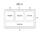
- FIG. 6 is a block diagram that represents the configuration of a data collection device.
- FIG. 7 is a diagram that represents a result of monitoring of photovoltaic power generation using a typical method.
- FIG. 8 is a flowchart of monitoring an amount of photovoltaic power generation according to an embodiment.
- FIG. 9 is a diagram that represents how to make a power generation graph based on a representative pattern.
- FIGS. 10 and 11 represent processes of monitoring when received data includes additional values other than a maximum amount of power generation.
- FIGS. 1 to 3 a system-associated photovoltaic device according to an embodiment is described with reference to FIGS. 1 to 3 .
- FIG. 1 is a block diagram of a system-associated photovoltaic device according to an embodiment.
- a system-associated photovoltaic device 100 includes a solar battery array 101 , an inverter 103 , an alternating current (AC) filter 105 , an AC/AC converter 107 , a system 109 , a charging control unit 111 , a battery energy storage system 113 , and a system control unit 115 .
- AC alternating current
- the solar battery array 101 is obtained by coupling a plurality of solar battery modules.
- the solar battery module is a device in which a plurality of solar batteries is connected in series or parallel to convert solar energy into electrical energy to generate a certain voltage and current.
- the solar battery array 101 absorbs solar energy to convert it into electrical energy.
- the inverter 103 inverts direct current (DC) power into AC power. It receives the DC power supplied by the solar battery array 101 or the DC power discharged by the battery energy storage system 113 through the charging control unit 111 to invert them into AC power.
- DC direct current
- the AC filter 105 filters the noise of power inverted into the AC power.
- the AC/AC converter 107 converts the size of a voltage of the AC power devoid of noise, and supplies the converted power to the system 109 .
- the system 109 is a system that incorporates many power stations, substations, power transmission and distribution cables, and loads to generate and use power.
- the charging control unit 111 controls the charging and discharging of the battery energy storage system 113 .
- the charging control unit 111 receives power from the battery energy storage system 113 and delivers it to the system.
- the charging control unit 111 receives power from the solar battery array 101 and delivers it to the battery energy storage system 113 .
- the battery energy storage system 113 receives electrical energy from the solar battery array 101 for charging and discharges the charged electrical energy according to the power supply and demand condition of the system 109 .
- the battery energy storage system 113 receives idle power from the solar battery array 101 for charging.
- the battery energy storage system 113 discharges charged power to supply power to the system 109 .
- the power supply and demand condition of the system has a big difference according to the time zone. Thus, it is inefficient that the system-associated photovoltaic device 100 uniformly supplies the power supplied by the solar battery array 101 without consideration of the power supply and demand condition of the system 109 .
- the system-associated photovoltaic device 100 uses the battery energy storage system 113 to adjust an amount of power supply according to the power supply and demand of the system 109 . Accordingly, the system-associated photovoltaic device 100 may efficiently supply power to the system 109 .
- the system control unit 115 controls the operations of the charging control unit 111 , the inverter 103 , the AC filter 105 , and the AC/AC converter 107 .
- the sensor unit 116 senses other elements related to photovoltaic power generation.
- the sensor unit 116 may include any one of a sunshine sensor and a temperature sensor.
- the sensor unit 116 may sense sunshine while photovoltaic power generation is performed.
- the sensor unit 116 may sense temperature while photovoltaic power generation is performed.
- FIG. 2 is a block diagram of a small-capacity system-associated photovoltaic device according to an embodiment.
- a small-capacity system-associated photovoltaic device 200 includes a solar battery array 101 , an inverter 103 , an AC filter 105 , an AC/AC converter 107 , a system 109 , a charging control unit 111 , a battery energy storage system 113 , a system control unit 115 , and a DC/DC converter 117 .
- the present embodiment is the same as the embodiment in FIG. 1 but further includes the DC/DC converter 117 .
- the DC/DC converter 117 converts the voltage of DC power generated by the solar battery array 101 .
- the voltage of power produced by the solar battery array 101 in the small-capacity system-associated photovoltaic device 200 is low. Thus, there is a need to boost the voltage in order to input power supplied by the solar battery array 101 to the inverter.
- the DC/DC converter 117 converts the voltage of power produced by the solar battery array 101 into a voltage that may be input to the inverter 103 .
- FIG. 3 is a flowchart of the operation of a system-associated photovoltaic device according to an embodiment.
- the solar battery array 101 converts solar energy into electrical energy in step S 101 .
- the system control unit 115 determines whether there is a need to supply power to the system 109 , in step S 103 . Whether there is a need to supply power to the system 109 may be determined based on whether the system 109 is a heavy load or light load.
- the system control unit 115 controls the charging control unit 111 to charge the battery energy storage system 113 , in step S 105 .
- the system control unit 115 may generate a control signal that controls the charging control unit 111 .
- the charging control unit 111 may receive the control signal to charge the battery energy storage system 113 .
- the system control unit 115 determines whether there is a need to discharge the battery energy storage system 113 , in step S 107 . It is possible to determine whether there is a need to discharge the battery energy storage system 113 because electrical energy supplied by the solar battery array 101 fails to satisfy the power demand of the system 109 . Also, the system control unit 115 may determine whether the battery energy storage system 113 stores sufficient electrical energy to be discharged.
- the system control unit 115 controls the charging control unit 111 to discharge the battery energy storage system 113 , in step S 109 .
- the system control unit 115 may generate a control signal that controls the charging control unit 111 .
- the charging control unit 111 may receive the control signal to discharge the battery energy storage system 113 .
- the inverter 103 inverts electrical energy discharged by the battery energy storage system 113 and electrical energy converted by the solar battery array 101 into AC, in step S 111 .
- the system-associated photovoltaic device 100 inverts both the electrical energy discharged by the battery energy storage system 113 and the electrical energy converted by the solar battery array 101 through a single inverter 103 .
- Each electric appliance has a limit in consumption power.
- the limit includes an instantaneous limit and a long-term limit, and maximum power that may be used without damage to a device for a long time is defined as rated power.
- the AC filter 105 filters the noise of inverted power, in step S 113 .
- the AC/AC converter 107 converts the size of a voltage of the filtered AC power to supply the converted power to the system 109 , in step S 115 .
- the system-associated photovoltaic device 100 supplies converted power to the system in step S 117 .
- the system-associated photovoltaic device 100 uses only a single inverter 103 , there are following limitations when the rated power of the inverter 103 is determined based on the capacity of the solar battery array 101 in order to design the system-associated photovoltaic device 100 .
- the battery energy storage system 113 discharges electricity and thus supplies electrical energy along with the solar battery array 101 , it is difficult to maximize the efficiency of the inverter 103 because the inverter 103 uses power exceeding 40% to 60% of the rated power.
- the battery energy storage system 113 discharges electricity and thus supplies electrical energy solely, it is difficult to maximize the efficiency of the inverter 103 because the inverter 103 uses power less than 40% to 60% of the rated power.
- the battery energy storage system 101 supplies a little amount of electrical energy, it is difficult to maximize the efficiency of the inverter 103 because the inverter 103 uses power less than 40% to 60% of the rated power.
- the efficiency with which the system-associated photovoltaic device 100 converts solar energy into electrical energy decreases.
- the total harmonic distortion (THD) of power increases, the quality of power that the system-associated photovoltaic device 100 produces goes down.
- FIG. 4 is a block diagram of a system-associated photovoltaic device according to another embodiment.
- a system-associated photovoltaic device 500 includes a solar battery array 501 , a first inverter 503 , an AC filter 505 , an AC/AC converter 507 , a system 509 , a control switch 511 , a charging control unit 513 , a battery energy storage system 515 , a system control unit 517 , and a second inverter 519 . Also, it is possible to further include a sensor unit 116 .
- the solar battery array 501 is obtained by coupling a plurality of solar battery modules.
- the solar battery module is a device in which a plurality of solar batteries is connected in series or parallel to convert solar energy into electrical energy to generate a certain voltage and current.
- the solar battery array 501 absorbs solar energy to convert it into electrical energy.
- the first inverter 503 inverts DC power into AC power. It receives the DC power supplied by the solar battery array 501 or the DC power discharged by the battery energy storage system 515 through the charging control unit 513 to invert them into AC power.
- the AC filter 505 filters the noise of power inverted into the AC power.
- the AC/AC converter 507 converts the size of a voltage of the AC power devoid of noise and supplies the converted power to the system 509 .
- the system 509 is a system that incorporates many power stations, substations, power transmission and distribution cables, and loads to generate and use power.
- the control switch 511 adjusts the flow of power supply between the battery energy storage system 515 and the first inverter 503 .
- the control switch 511 receives a control signal from the system control unit 517 to operate according to the control signal.
- the system control unit 517 when the battery energy storage system 515 discharges electricity to supply power to the first inverter 503 , the system control unit 517 generates a control signal that connects the control switch 511 and the first inverter 503 .
- the control switch 511 receives the control signal to connect the charging control unit 513 and the first inverter 503 .
- the system control unit 517 When power is not supplied to the first inverter 503 , the system control unit 517 generates a control signal that disconnects the control switch 511 from the first inverter.
- the control switch 511 receives the control signal to be disconnected from the first inverter 503 .
- the charging control unit 513 controls the charging and discharging of the battery energy storage system 515 .
- the charging control unit 513 receives power from the battery energy storage system 515 and delivers it to the system.
- the charging control unit 513 may supply power to any one of the first inverter or the second inverter 519 or to both the first inverter 503 and the second inverter 519 .
- the charging control unit 513 receives power from the solar battery array 501 and delivers it to the battery energy storage system 515 .
- the battery energy storage system 515 receives idle power from the solar battery array 501 for charging, when the system is the light load.
- the battery energy storage system 515 discharges charged power to supply power to the system 509 , when the system is the heavy load.
- the system-associated photovoltaic device 500 may use the battery energy storage system 515 to efficiently power to the system 509 .
- the system control unit 517 controls the operations of the charging control unit 513 , the first inverter 503 , the second inverter 519 , the AC filter 505 , and the AC/AC converter 507 .
- the embodiment in FIG. 4 further includes the second inverter 519 that is connected to the battery energy storage system 515 .
- the second inverter 519 inverts DC power into AC power. It receives the DC power discharged by the battery energy storage system 515 through the charging control unit 513 and inverts the received DC power into AC power. By including the second inverter 519 besides the first inverter 503 , the first inverter or the second inverter selectively operates according to the size of power supplied by the system-associated photovoltaic device 500 .
- FIG. 5 is a block diagram that represents the configuration of a photovoltaic system 1 .
- a solar inverter 103 may be included in the photovoltaic device 100 . Since the solar inverter 103 has been described above in detail, related descriptions are omitted in FIG. 5 .
- the solar inverter 103 may exist in singularity or in plurality in the photovoltaic device 100 .
- the photovoltaic inverter 103 may deliver an amount of photovoltaic power generation to a data collection device 300 .
- the sensor unit 116 of the photovoltaic device 100 may deliver sensed data along with the amount of photovoltaic power generation to the data collection device 300 .
- the sensed data may include at least one of sunshine, temperature, sunrise/sunset time, and a weather condition.
- the photovoltaic device may deliver power generation time information along with the above-described data to the data collection device 300 .
- the data collection device 300 receives and synthesizes data from a lower inverter 103 and the photovoltaic device 100 .
- the data collection device 300 may be a component in the photovoltaic device 100 or may be a separate component that is connected to a plurality of photovoltaic devices 100 .
- the data collection device 300 may provide the collected power generation information to users or clients for monitoring. Also, when there is a upper server 400 connected to the plurality of data collection devices 300 , it is possible to deliver the collected power generation information to the upper server 400 .
- the data collection device 300 is described in detail with reference to FIG. 6 .
- the data collection device 300 may include a control unit 315 , a transceiver 316 , a storage unit 317 , and an output unit 318 , as shown in FIG. 5 .
- the embodiment is not limited to components in FIG. 5 and may further include other components as needed.
- the transceiver 316 receives photovoltaic power generation related data from the photovoltaic device 100 that includes the inverter 103 and various sensors (not shown).
- a reception method may include both wired and wireless communication methods.
- the data collection device 300 is a component in the photovoltaic device 100 , it is possible to receive data through a circuit that is connected to between internal components.
- the transceiver 316 may receive an amount of photovoltaic power generation from the inverter 103 and deliver the received amount of power generation to the control unit 315 .
- the transceiver 316 may transmit the collected photovoltaic power generation data to the upper server 400 . Likewise, it is possible to transmit the data to the upper server 400 through wired/wireless communication.
- the transceiver 316 may also transmit the amount of photovoltaic power generation to users and clients. In particular, it is possible to transmit information for monitoring the amount of power generation to the owner of the photovoltaic device 100 or to an electricity dealer.
- the transceiver 316 may also be divided into a transceiver and a receiver.
- the storage unit 317 stores the collected power generation data. Photovoltaic power generation is performed everyday, and the data collected by the data collection device 300 is stored in the storage unit 317 for the time being and transmitted to another place. The data stored in the storage unit 317 may be utilized for decreasing transmission data to be described below.
- the storage unit 317 stores a representative pattern of a graph that may be referred to in order to make a graph for monitoring an amount of photovoltaic power generation.
- the stored representative pattern may be in singularity or in plurality with respect to each condition.
- the output unit 318 may display data for monitoring the amount of photovoltaic power generation.
- the output unit may include a display unit that visually displays data, and a speaker that auditorily outputs data.
- the control unit 315 controls the operations of the above-described transceiver 316 , storage unit 317 , and output unit 318 . Furthermore, the control unit 315 may process the received data to generate difference data. How to process the data is described below in detail.
- the photovoltaic system 1 may include the upper server 400 to which the plurality of data collection devices 300 are connected.
- the upper server 400 may synthesize and collect photovoltaic power generation information that is delivered from the plurality of data collection devices 300 .
- the upper server 400 may not separately exist and the data collection device 300 may also function as the upper server.
- the upper server 400 may control both the lower data collection device 300 and the photovoltaic device 100 , and by collecting data from a plurality of photovoltaic devices, it is possible to compare amounts of power generation of the power generation devices 100 and control malfunction. Also, the upper server 400 may provide the data received from the photovoltaic device 100 or the data collection device 300 and a graph for monitoring to users. For example, the upper server 400 may provide the amount of photovoltaic power generation and related data received from the data collection device 300 to users. Also, the upper server 400 may provide users with the graph for monitoring that is received from the data collection device 300 . Also, the upper server 400 may make the graph for monitoring based on the amount of photovoltaic power generation and related data that is received from the data collection device 300 , and provide the graph to users.
- FIG. 7 is a diagram that represents a result of monitoring of photovoltaic power generation using a typical method.
- the data collection device 300 has typically collected data needed for monitoring from a solar inverter and various sensors.
- the control unit 315 of the data collection device 300 may provide users with a result of monitoring that is based on the collected data, or deliver the result of monitoring to the upper server.
- the data collection device 300 has typically collected an amount of photovoltaic power generation at a certain time interval (e.g., every five minutes) to monitor the amount of photovoltaic power generation, as shown in FIG. 7 .
- a certain time interval e.g., every five minutes
- a transmission data amount increases because all amounts of power generation are transmitted at intervals.
- communication charge increases in proportion to the increased data amount.
- FIGS. 8 to 11 a photovoltaic device that supplements typical limitations is described with reference to FIGS. 8 to 11 .
- FIG. 8 is a flowchart of monitoring an amount of photovoltaic power generation according to an embodiment.
- the transceiver 316 of the data collection device 300 receives only specific partial data on photovoltaic power generation from the inverter 103 of the photovoltaic device 100 , in step S 301 .
- the specific data may be a time at which power generation starts, a time at which power generation ends, and a maximum amount of power generation.
- position information on the photovoltaic device may be latitude and longitude information.
- the transceiver 316 may also receive only a maximum amount of power generation.
- the times at which power generation starts and ends may be found based on previously input position data on the photovoltaic device. Since photovoltaic power generation is directly concerned in sunrise and sunset times, it is possible to find sunrise and sunset times according to the position data to infer the time at which power generation starts and ends.
- the control unit 315 of the data collection device 300 may use pre-stored position information to find the times at which power generation starts and ends with reference to a table related to sunrise and sunset. Since data on sunrise and sunset is already accumulated for each region, it is possible to put and use the data into a table.
- the table may be stored in the storage unit 317 .
- the data collection device 300 may receive, along with power generation amount information, information for identifying a power generation device transmitting the power generation amount information and the control unit 315 may obtain position information on the photovoltaic device 100 based on identification information.
- control unit 315 may calculate sunrise and sunset times based on position information.
- the control unit 315 may find times at which photovoltaic power generation starts and ends by using an algorithm that calculates sunrise and sunset according to latitude, longitude, and a date.
- the control unit 315 calls a representative pattern of a photovoltaic power generation amount graph from the storage unit 121 , in step S 311 . This process is described in more detail with reference to FIG. 9 .
- FIG. 9 is a diagram that represents how to make a power generation amount graph based on a representative pattern.
- a pattern A, a pattern B, and a pattern C may be stored in the storage unit as representative patterns in an embodiment.
- a relatively large number of patterns may be stored in a region where climate frequently varies (e.g., Korea) and a relatively small number of patterns may be stored in a region where climate rarely varies (e.g., desert).
- Corresponding patterns may be stored upon the initial system design or may be newly stored according to a position at which the photovoltaic device is installed, during operation.
- the pattern A is a pattern in which a time at which power generation starts is earliest and values close to a maximum amount of power generation are maintained for a long time.
- a corresponding pattern may be a power generation amount pattern that corresponding to summer in which there is a lot of sunshine and day is relatively long.
- the pattern C is a pattern in which the time at which power generation starts is latest and values close to a maximum amount of power generation are short.
- a corresponding pattern may be a power generation amount pattern that corresponding to winter in which there is less sunshine and day is relatively short.
- the control unit 315 compares the received time at which power generation starts, the received time at which power generation ends, and the received maximum amount of power generation with a graph called from the storage unit 317 , in step S 321 .
- each stored pattern has times at which power generation starts and ends as characteristics, it is possible to compare the received data with stored patterns to select the most similar pattern. For example, when the times at which power generation starts and ends have smallest differences from the pattern A, the control unit 315 may select the pattern A.
- control unit 315 may preferentially select a graph that has been selected most recently, when received data has a difference difficult to distinguish from two or more patterns. For example, when the currently received data has an intermediate value between the patterns A and B and thus it is difficult to select, it is possible to select the pattern B as a result of comparison if a graph for monitoring is made based on the pattern B for the past one week.
- the control unit 315 makes a graph for monitoring base don a result of comparing the received specific data with a graph pattern called from the storage unit 317 , in step S 331 .
- a corresponding graph may be made in the photovoltaic device 100 .
- the corresponding graph may be made through a higher server. In the latter case, the photovoltaic device 100 may transmit the made graph, and it may transmit only specific data for making the graph and the higher server may select a graph pattern to make the graph.
- FIGS. 10 and 11 represent processes of monitoring when received data includes additional values other than a maximum amount of power generation.
- step S 322 it is determined whether there are values other than the maximum amount of power generation in data, in step S 322 . Since an amount of photovoltaic power generation fundamentally has almost a constant pattern, it is possible to make a rough graph if there is data on a maximum amount of power generation, and there may be sections that represent accidental values according to a climate condition. For example, in the case that it has rained from 9 AM to 11 AM, sunshine decreases while it rains and thus an amount of power generation has no choice but to decrease in proportion thereto. In this case, since there are sections that have different values from stored patterns, there may be a need to make a graph to reflect it.
- control unit 315 when it is determined that there are no values other than a maximum amount of power generation, the control unit 315 returns to step S 331 to make a graph.
- control unit 315 determines that there are values other than the maximum amount of power generation, a graph model for an exceptional situation is called from the storage unit 317 , in step S 323 .
- the graph for the exceptional situation may be a pattern for a rainy situation or a cloudy situation.
- the storage unit 317 may store a representative pattern for each weather situation based on accumulated data.
- the control unit 315 compares another of the received values with the graph for the exceptional situation that is called from the storage unit 317 , in step S 314 .
- the received data may be data on from a time at which power generation starts to a time at which an amount of power generation decreases before reaching the maximum amount of power generation. Also, it may be data on a time at which the amount of power generation recovers since a time at which the amount of power generation decreases. In addition, it may be data on a minimum amount of power generation in each exceptional situation section.
- the system control unit 315 may compare information on a section where there is a variation in amount of power generation, with the data on the minimum amount of power generation to select a closest pattern.
- a corresponding pattern is selected to modify the graph of the exceptional section in step S 325 .
- a section # 1 at which an amount of photovoltaic power generation varies may be represented in an embodiment according to a weather condition.
- the control unit 315 may receive data on the start time of # 1 , the end time of # 1 , and the minimum amount of power generation of # 1 through the transceiver 316 .
- the control unit 315 may call a graph pattern for an exceptional situation from the storage unit as described above, and make a power generation amount graph for monitoring according to the most similar pattern.
- control unit 315 receives all data on the exceptional section through the transceiver 316 in step S 326 .
- the control unit 315 receives data on an entire amount of power generation from the start time of # 1 to the end time of # 1 through the transceiver 316 .
- the control unit 315 receives data on an entire amount of power generation from the start time of # 1 to the end time of # 1 through the transceiver 316 .
- step S 325 data on an exceptional section is received to modify the entire graph in the same manner in step S 325 .
- the process of making the graph in FIG. 10 may also be performed within the photovoltaic device 100 or by a higher server.
- the data monitoring method as described above may be used for all data that has a constant pattern, such as sunshine or temperature, as well as an amount of photovoltaic power generation.
- Embodiments are mostly described above. However, they are only examples and do not limit the present disclosure. A person skilled in the art may appreciate that many variations and applications not presented above may be implemented without departing from the essential characteristic of embodiments. For example, each component particularly represented in embodiments may vary. In addition, it should be construed that differences related to such a variation and such an application are included in the scope of the present disclosure defined in the following claims.
Landscapes
- Engineering & Computer Science (AREA)
- Power Engineering (AREA)
- Charge And Discharge Circuits For Batteries Or The Like (AREA)
- Supply And Distribution Of Alternating Current (AREA)
- Photovoltaic Devices (AREA)
Abstract
Description
Claims (10)
Applications Claiming Priority (2)
| Application Number | Priority Date | Filing Date | Title |
|---|---|---|---|
| KR1020150014856A KR101965820B1 (en) | 2015-01-30 | 2015-01-30 | Photovoltaic data collecting device |
| KR10-2015-0014856 | 2015-01-30 |
Publications (2)
| Publication Number | Publication Date |
|---|---|
| US20160226440A1 US20160226440A1 (en) | 2016-08-04 |
| US10425036B2 true US10425036B2 (en) | 2019-09-24 |
Family
ID=55072527
Family Applications (1)
| Application Number | Title | Priority Date | Filing Date |
|---|---|---|---|
| US14/989,719 Expired - Fee Related US10425036B2 (en) | 2015-01-30 | 2016-01-06 | Photovoltaic data collection device |
Country Status (6)
| Country | Link |
|---|---|
| US (1) | US10425036B2 (en) |
| EP (1) | EP3051662B1 (en) |
| JP (1) | JP6093053B2 (en) |
| KR (1) | KR101965820B1 (en) |
| CN (1) | CN105846778B (en) |
| ES (1) | ES2651338T3 (en) |
Families Citing this family (2)
| Publication number | Priority date | Publication date | Assignee | Title |
|---|---|---|---|---|
| CN106873730A (en) * | 2017-03-20 | 2017-06-20 | 江苏师范大学 | A kind of photovoltaic data collection process device |
| JP7766363B1 (en) | 2024-06-14 | 2025-11-10 | 株式会社エンブルー | A management system for managing solar power generation facilities, and a management server for managing solar power generation facilities. |
Citations (16)
| Publication number | Priority date | Publication date | Assignee | Title |
|---|---|---|---|---|
| US4636931A (en) * | 1985-06-28 | 1987-01-13 | Shikoku Denryoku Kabushiki Kaisha | Photovoltaic power control system |
| JPS6290984A (en) | 1985-06-28 | 1987-04-25 | Shikoku Electric Power Co Inc | Solar photovoltaic generation control system |
| JP2001352693A (en) | 2000-06-09 | 2001-12-21 | Sharp Corp | Solar generator and its control system |
| CN101375408A (en) | 2006-05-17 | 2009-02-25 | 英弘精机株式会社 | Solar cell characteristic evaluation device |
| EP2061088A2 (en) | 2007-11-16 | 2009-05-20 | Meta System S.p.A. | Upgraded photovoltaic system |
| JP2010028899A (en) | 2008-07-15 | 2010-02-04 | Mitsubishi Electric Corp | Display device and method |
| CN101769788A (en) | 2009-12-29 | 2010-07-07 | 青海国泰节能技术研究院 | Method for forecasting optical output power and electric energy production of photovoltaic power station |
| US20110088743A1 (en) * | 2009-10-15 | 2011-04-21 | Yuhao Luo | Method to manage a photovoltaic system |
| CN102158129A (en) | 2011-01-30 | 2011-08-17 | 浙江昱能光伏科技集成有限公司 | Solar photovoltaic system and fault detection method thereof |
| CN102243135A (en) | 2011-04-15 | 2011-11-16 | 河海大学 | Method for diagnosing and analyzing failures of heliostat of tower-type solar power plant |
| JP2012138448A (en) | 2010-12-27 | 2012-07-19 | National Institute Of Advanced Industrial & Technology | Output drop detector and detection method of photovoltaic power generation |
| US20120256612A1 (en) * | 2009-12-11 | 2012-10-11 | Corinne Alonso | System For The Electronic Management Of Photovoltaic Cells With Adapted Thresholds |
| CN203086512U (en) | 2012-12-27 | 2013-07-24 | 北京唯绿建筑节能科技有限公司 | Solar photovoltaic power generation monitoring device with communication function |
| JP2014082309A (en) | 2012-10-16 | 2014-05-08 | Mitsubishi Electric Corp | Device for managing photovoltaic power generation system |
| US20150013748A1 (en) * | 2012-02-17 | 2015-01-15 | Djordje Garabandic | Maximum power point tracking (mppt) |
| US9641021B2 (en) * | 2013-01-31 | 2017-05-02 | General Electric Company | Photovoltaic power generation system including apparatus and method to buffer power fluctuations |
-
2015
- 2015-01-30 KR KR1020150014856A patent/KR101965820B1/en not_active Expired - Fee Related
-
2016
- 2016-01-05 EP EP16150176.2A patent/EP3051662B1/en not_active Not-in-force
- 2016-01-05 ES ES16150176.2T patent/ES2651338T3/en active Active
- 2016-01-06 US US14/989,719 patent/US10425036B2/en not_active Expired - Fee Related
- 2016-01-28 CN CN201610060337.0A patent/CN105846778B/en not_active Expired - Fee Related
- 2016-01-29 JP JP2016015351A patent/JP6093053B2/en not_active Expired - Fee Related
Patent Citations (17)
| Publication number | Priority date | Publication date | Assignee | Title |
|---|---|---|---|---|
| JPS6290984A (en) | 1985-06-28 | 1987-04-25 | Shikoku Electric Power Co Inc | Solar photovoltaic generation control system |
| US4636931A (en) * | 1985-06-28 | 1987-01-13 | Shikoku Denryoku Kabushiki Kaisha | Photovoltaic power control system |
| JP2001352693A (en) | 2000-06-09 | 2001-12-21 | Sharp Corp | Solar generator and its control system |
| CN101375408A (en) | 2006-05-17 | 2009-02-25 | 英弘精机株式会社 | Solar cell characteristic evaluation device |
| EP2061088A2 (en) | 2007-11-16 | 2009-05-20 | Meta System S.p.A. | Upgraded photovoltaic system |
| JP2010028899A (en) | 2008-07-15 | 2010-02-04 | Mitsubishi Electric Corp | Display device and method |
| US20110088743A1 (en) * | 2009-10-15 | 2011-04-21 | Yuhao Luo | Method to manage a photovoltaic system |
| US20120256612A1 (en) * | 2009-12-11 | 2012-10-11 | Corinne Alonso | System For The Electronic Management Of Photovoltaic Cells With Adapted Thresholds |
| US9515517B2 (en) * | 2009-12-11 | 2016-12-06 | Total Marketing Services | System for the electronic management of photovoltaic cells with adapted thresholds |
| CN101769788A (en) | 2009-12-29 | 2010-07-07 | 青海国泰节能技术研究院 | Method for forecasting optical output power and electric energy production of photovoltaic power station |
| JP2012138448A (en) | 2010-12-27 | 2012-07-19 | National Institute Of Advanced Industrial & Technology | Output drop detector and detection method of photovoltaic power generation |
| CN102158129A (en) | 2011-01-30 | 2011-08-17 | 浙江昱能光伏科技集成有限公司 | Solar photovoltaic system and fault detection method thereof |
| CN102243135A (en) | 2011-04-15 | 2011-11-16 | 河海大学 | Method for diagnosing and analyzing failures of heliostat of tower-type solar power plant |
| US20150013748A1 (en) * | 2012-02-17 | 2015-01-15 | Djordje Garabandic | Maximum power point tracking (mppt) |
| JP2014082309A (en) | 2012-10-16 | 2014-05-08 | Mitsubishi Electric Corp | Device for managing photovoltaic power generation system |
| CN203086512U (en) | 2012-12-27 | 2013-07-24 | 北京唯绿建筑节能科技有限公司 | Solar photovoltaic power generation monitoring device with communication function |
| US9641021B2 (en) * | 2013-01-31 | 2017-05-02 | General Electric Company | Photovoltaic power generation system including apparatus and method to buffer power fluctuations |
Non-Patent Citations (3)
| Title |
|---|
| European Patent Office Application Serial No. 16150176.2, Search Report dated May 6, 2016, 6 pages. |
| Japan Patent Office Application Serial No. 2016-015351, Office Action dated Sep. 13, 2016, 2 pages. |
| State Intellectual Property Office of the People's Republic of China Application Serial No. 201610060337.0, Office Action dated Jun. 9, 2017, 8 pages. |
Also Published As
| Publication number | Publication date |
|---|---|
| KR101965820B1 (en) | 2019-04-04 |
| JP2016144393A (en) | 2016-08-08 |
| JP6093053B2 (en) | 2017-03-08 |
| KR20160093925A (en) | 2016-08-09 |
| US20160226440A1 (en) | 2016-08-04 |
| EP3051662A1 (en) | 2016-08-03 |
| CN105846778B (en) | 2018-07-17 |
| EP3051662B1 (en) | 2017-09-27 |
| ES2651338T3 (en) | 2018-01-25 |
| CN105846778A (en) | 2016-08-10 |
Similar Documents
| Publication | Publication Date | Title |
|---|---|---|
| US9785168B2 (en) | Power generation amount prediction apparatus, method for correcting power generation amount prediction, and natural energy power generation system | |
| USRE46156E1 (en) | Hybrid energy storage system, renewable energy system including the storage system, and method of using same | |
| CN104345355B (en) | A kind of collection and device, the method and system of processing weather data and image | |
| US9225174B2 (en) | Control system, control apparatus and control method | |
| KR20220060547A (en) | Spare generators and associated power systems | |
| CN105075054B (en) | Power conversion device, control system and control method | |
| CN104659849A (en) | Device, system and charging method of charging pile | |
| JP5592772B2 (en) | Power supply control device and power supply system using the same | |
| US10243504B2 (en) | Photovoltaic system | |
| US20130234516A1 (en) | Electricity generation controller, electricity generation control system, and electricity generation control method | |
| US9887548B2 (en) | Power management apparatus and power management method | |
| US10425036B2 (en) | Photovoltaic data collection device | |
| CN105703490B (en) | Micro energy capture device and capture method thereof | |
| CN105144533A (en) | Module for storing/retrieving electricity in/from an electric energy storage device suitable for use in a photovoltaic system, photovoltaic system and method for upgrading a photovoltaic system | |
| CN106356978B (en) | A smart solar charger | |
| CN110867934A (en) | Commercial power solar charging module sharing system | |
| US20210336447A1 (en) | Smart balancing energy charging control system | |
| CN203596618U (en) | Cabinet-type DC power supply system | |
| JP5985871B2 (en) | Power management apparatus, management server, local weather information generation system, and local weather information generation method | |
| CN104518561A (en) | Civil direct current system and direct current power supply method | |
| US20160248374A1 (en) | Photovoltaic system | |
| CN202383223U (en) | Energy-saving remote detecting system for electrical load | |
| US20180323614A1 (en) | Apparatus control device, apparatus control system, and apparatus control method | |
| CN119154346A (en) | Energy allocation system based on vehicle-mounted battery | |
| CN105897151A (en) | Photovoltaic terminal box |
Legal Events
| Date | Code | Title | Description |
|---|---|---|---|
| AS | Assignment |
Owner name: LSIS CO., LTD., KOREA, REPUBLIC OF Free format text: ASSIGNMENT OF ASSIGNORS INTEREST;ASSIGNORS:LEE, SEONG JOON;CHO, CHOONG KUN;SIGNING DATES FROM 20151228 TO 20151229;REEL/FRAME:037451/0561 |
|
| STPP | Information on status: patent application and granting procedure in general |
Free format text: FINAL REJECTION MAILED |
|
| STPP | Information on status: patent application and granting procedure in general |
Free format text: RESPONSE AFTER FINAL ACTION FORWARDED TO EXAMINER |
|
| STPP | Information on status: patent application and granting procedure in general |
Free format text: ADVISORY ACTION MAILED |
|
| STPP | Information on status: patent application and granting procedure in general |
Free format text: NOTICE OF ALLOWANCE MAILED -- APPLICATION RECEIVED IN OFFICE OF PUBLICATIONS |
|
| STPP | Information on status: patent application and granting procedure in general |
Free format text: PUBLICATIONS -- ISSUE FEE PAYMENT RECEIVED |
|
| STPP | Information on status: patent application and granting procedure in general |
Free format text: PUBLICATIONS -- ISSUE FEE PAYMENT VERIFIED |
|
| STCF | Information on status: patent grant |
Free format text: PATENTED CASE |
|
| FEPP | Fee payment procedure |
Free format text: MAINTENANCE FEE REMINDER MAILED (ORIGINAL EVENT CODE: REM.); ENTITY STATUS OF PATENT OWNER: LARGE ENTITY |
|
| LAPS | Lapse for failure to pay maintenance fees |
Free format text: PATENT EXPIRED FOR FAILURE TO PAY MAINTENANCE FEES (ORIGINAL EVENT CODE: EXP.); ENTITY STATUS OF PATENT OWNER: LARGE ENTITY |
|
| STCH | Information on status: patent discontinuation |
Free format text: PATENT EXPIRED DUE TO NONPAYMENT OF MAINTENANCE FEES UNDER 37 CFR 1.362 |
|
| FP | Lapsed due to failure to pay maintenance fee |
Effective date: 20230924 |