US10423737B2 - Numerical simulation of objects being released onto a surface in a manufacturing process - Google Patents
Numerical simulation of objects being released onto a surface in a manufacturing process Download PDFInfo
- Publication number
- US10423737B2 US10423737B2 US15/651,419 US201715651419A US10423737B2 US 10423737 B2 US10423737 B2 US 10423737B2 US 201715651419 A US201715651419 A US 201715651419A US 10423737 B2 US10423737 B2 US 10423737B2
- Authority
- US
- United States
- Prior art keywords
- bdems
- receiving surface
- arbitrarily
- lower receiving
- shaped objects
- Prior art date
- Legal status (The legal status is an assumption and is not a legal conclusion. Google has not performed a legal analysis and makes no representation as to the accuracy of the status listed.)
- Active, expires
Links
Images


Classifications
-
- G—PHYSICS
- G06—COMPUTING OR CALCULATING; COUNTING
- G06F—ELECTRIC DIGITAL DATA PROCESSING
- G06F30/00—Computer-aided design [CAD]
- G06F30/10—Geometric CAD
- G06F30/17—Mechanical parametric or variational design
-
- G06F17/5009—
-
- G—PHYSICS
- G06—COMPUTING OR CALCULATING; COUNTING
- G06F—ELECTRIC DIGITAL DATA PROCESSING
- G06F30/00—Computer-aided design [CAD]
- G06F30/20—Design optimisation, verification or simulation
- G06F30/23—Design optimisation, verification or simulation using finite element methods [FEM] or finite difference methods [FDM]
-
- G06F17/5018—
-
- G06F17/5086—
-
- G—PHYSICS
- G06—COMPUTING OR CALCULATING; COUNTING
- G06F—ELECTRIC DIGITAL DATA PROCESSING
- G06F30/00—Computer-aided design [CAD]
- G06F30/20—Design optimisation, verification or simulation
-
- G—PHYSICS
- G06—COMPUTING OR CALCULATING; COUNTING
- G06F—ELECTRIC DIGITAL DATA PROCESSING
- G06F2111/00—Details relating to CAD techniques
- G06F2111/10—Numerical modelling
-
- G06F2217/16—
Definitions
- the invention generally relates to computer aided mechanical engineering analysis, more particularly to methods and systems for numerically simulating various arbitrarily-shaped objects being released onto a surface in a manufacturing process.
- CAE computer aided engineering
- FEA finite element analysis
- the FEA software is provided with a model of the geometric description and the associated material properties at each point within the model (sometimes referred to as a FEA mesh model).
- a model of the geometric description and the associated material properties at each point within the model (sometimes referred to as a FEA mesh model).
- the geometry of the system under analysis is represented by solids, shells and beams of various sizes, which are referred to as finite elements.
- the vertices of the finite elements are referred to as nodes.
- the model is comprised of a finite number of finite elements, which are assigned a material name to associate with material properties.
- the model thus represents the physical space occupied by the object under analysis along with its immediate surroundings.
- the FEA software then refers to a table in which the properties (e.g., stress-strain constitutive equation, Young's modulus, Poisson's ratio, thermo-conductivity) of each material type are tabulated. Additionally, the conditions at the boundary of the object (i.e., loadings, physical constraints, etc.) are specified. In this fashion a model of the object and its environment is created.
- properties e.g., stress-strain constitutive equation, Young's modulus, Poisson's ratio, thermo-conductivity
- DEM discrete element method
- distinct element method Another technique is referred to as discrete element method (DEM) or distinct element method, which is generally used for numerically simulating the motion of a large number of particles.
- DEM discrete element method
- Today DEM is becoming widely accepted as an effective method of addressing engineering problems in granular and discontinuous materials.
- Modern manufacturing process is generally automated with many machines in a factory.
- one machine may be designed for drawing food products out of a hopper/container and feeding onto a conveyor for further processing.
- many factors need to be considered, for example, type of food products, amount and speed of food products being released to the conveyor, and characteristics of the conveyor (e.g., angle, type, speed, etc.).
- Many prior art approaches are generally inefficient, for example, requiring a Priori knowledge, ad hoc design, etc. Therefore, it would be desirable to have improved systems and methods of numerically simulating various arbitrarily-shaped objects being released onto a receiving surface in a manufacturing process.
- a numerical simulation method of moving various arbitrarily-shaped objects from an egress area onto a lower surface in manufacturing process includes: receiving, in a computer system, a manufacturing process configuration specification for moving various types of arbitrarily-shaped objects from a horizontal egress area onto a lower receiving surface with desired mass flow rate in a predefined time period, the specification defining properties of each of the various types of the arbitrarily-shaped objects including shape, size, strength and mass distribution, the specification further defining size and shape of the egress area and characteristics of the lower receiving surface; creating a finite element analysis (FEA) model representing the lower receiving surface corresponding to the defined characteristics including width, relative location and orientation to the egress area; creating respective bonded discrete element models (BDEMs) representing the various types of the arbitrarily-shaped objects, each BDEM containing a plurality of discrete elements connected by connection bonds in accordance with the defined properties; generating a list of BDEMs each with randomly-chosen types and orientation,
- FFA finite element analysis
- FIGS. 1A-1C collectively show a flowchart illustrating an example process of numerically simulating of moving various arbitrarily-shaped objects from an egress area onto a lower receiving surface in manufacturing process, according to an embodiment of the invention
- FIG. 2 is a diagram showing a first example manufacturing process configuration, according to an embodiment of the invention.
- FIG. 3 is a diagram showing a second example manufacturing process configuration, according to an embodiment of the invention.
- FIGS. 4A-4C are elevation profiles showing examples of relative location and orientation of the lower receiving surface in relation to the horizontal egress area in accordance with an embodiment of the invention
- FIG. 5 is a two-dimensional view depicting three example bonded discrete element models (BDEMs), according to an embodiment of the invention.
- BDEMs bonded discrete element models
- FIG. 6 is a diagram showing an example list of BDEMs in accordance with one embodiment of the invention.
- FIG. 7 is a diagram showing an example egress area partitioned into a number of ‘open’ sub-regions in accordance with one embodiment of the invention.
- FIG. 8 is a diagram showing an example egress area after being placed with relevant portion of the list of BDEMs in accordance with one embodiment of the invention.
- FIG. 9 is a diagram showing an example of moving various types of arbitrarily-shaped objects from an egress area onto a lower receiving surface in accordance with one embodiment of the invention.
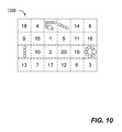
- FIG. 10 is a diagram showing an example egress area after each solution cycle of a time-marching simulation of moving various types of arbitrarily-shaped objects from an egress area onto a lower receiving surface in accordance with one embodiment of the invention.
- FIG. 11 is a function diagram showing salient components of a computing device, in which an embodiment of the invention may be implemented.
- references herein to “one embodiment” or “an embodiment” means that a particular feature, structure, or characteristic described in connection with the embodiment can be included in at least one embodiment of the invention.
- the appearances of the phrase “in one embodiment” in various places in the specification are not necessarily all referring to the same embodiment, nor are separate or alternative embodiments mutually exclusive of other embodiments. Further, the order of blocks in process flowcharts or diagrams representing one or more embodiments of the invention do not inherently indicate any particular order nor imply any limitations in the invention.
- FIGS. 1A-11 Embodiments of the invention are discussed herein with reference to FIGS. 1A-11 . However, those skilled in the art will readily appreciate that the detailed description given herein with respect to these figures is for explanatory purposes as the invention extends beyond these limited embodiments.
- FIGS. 1A-1C it is collectively shown a flowchart illustrating an example process 100 of numerically simulating of moving various arbitrarily-shaped objects from an egress area onto a lower surface in manufacturing process in accordance with an embodiment of the invention.
- Process 100 is preferably implemented in software and understood with other figures.
- Process 100 starts at action 102 by receiving a manufacturing process configuration specification for moving various types of arbitrarily-shaped objects from a horizontal egress area onto a lower receiving surface with a desired mass flow rate in a predefined time period in a computer system (e.g., computer system 1100 of FIG. 11 ) having at least one application module installed thereon.
- Application module may be software products based on finite element method, discrete element method, etc.
- the term “horizontal” used herein is as a reference orientation, for example, horizontal egress area is shown horizontally in the figures, which is perpendicular to the direction of gravity.
- the manufacturing process configuration specification defines properties of each type of the arbitrarily-shaped objects that include shape, size, strength and mass distribution, etc.
- the configuration specification also defines size and shape of the egress area and characteristics of the lower receiving surface.
- a finite element analysis (FEA) model is created for representing the lower receiving surface based on the defined characteristics, which includes, but is not limited to, width, relative location and orientation to the egress area.
- FEA finite element analysis
- FIG. 2 is a diagram showing a first example manufacturing process configuration 200 showing a horizontal egress area 210 , a lower receiving surface 220 .
- Various arbitrarily-shaped objected are moved from the egress area 210 onto the lower receiving surface 220 .
- the receiving lower surface 220 has a width 222 and optional moving speed 230 (e.g., a conveyor).
- the relative location and orientation of the lower receiving surface 220 in relation to the egress area 210 can be defined by a distance 215 and slope of the lower surface (see examples shown in FIGS. 4A-4C ).
- FIG. 3 shows a second example manufacturing process configuration 300 .
- Egress area 310 has an elliptical area instead of rectangular area of the first example.
- Lower receiving surface 320 contains raised edges or guard rails 326 located on either side. Raised edges 326 may provide certain protection for objects being bounced out when dropping down from the egress area 320 .
- FIGS. 4A-4C Three example different relative locations 415 a - c and orientations of a lower receiving surface 420 a - c to the egress area 410 a - c are shown as vertical elevation views in FIGS. 4A-4C .
- egress area 410 a and lower receiving surface 420 a are in parallel.
- egress area 410 b - c and lower receiving surface 420 b - c are not parallel to each other.
- the slopes are different in the examples shown in FIGS. 4A-4C .
- BDEMs respective bonded discrete element models
- Each BDEM contains a plurality of discrete elements connected by connection bonds in accordance with defined properties received in the manufacturing process configuration specification.
- FIG. 5 shows three examples of BDEMs.
- Each BDEM contains a plurality of either homogeneous or heterogeneous discrete elements (i.e., circles in two-dimension or spheres in three-dimension).
- Discrete elements are connected by the connection bonds (shown as broken lines). Based on defined properties, any arbitrarily-shaped objects can be modeled with this methodology. Connection bonds can be used for representing the structural strength, while discrete elements represent shape, size and mass distribution.
- the first example BDEM 510 contains four substantially similar sized discrete elements 511 connected by three connection bonds 512 in a bar type of structure (i.e., an I-shaped object).
- the second example BDEM 520 contains seven substantially similar discrete elements (DEs) 521 and one larger DE 529 connected by connection bonds 522 in a ring type of structure (i.e., an O-shaped object).
- the third example BDEM 530 contains one DE 539 and eight smaller DEs 531 connected by connection bonds 532 in a C-shaped object.
- a list of BDEMs is generated.
- Each BDEM in the list has a randomly-chosen type (e.g., one of the three types shown in FIG. 5 ) along with a randomly-chosen orientation (i.e., each object may be arbitrarily-rotated in a space either two- or three-dimensional).
- An example list of BDEMs 600 is shown in FIG. 6 .
- the total mass of the list is calculated as each BDEM is added.
- the target total mass is equal to the desired mass flow rate multiplied by the predefined time period.
- All of the BDEMs in the list are initially set as ‘inactive’ including all discrete elements and corresponding connection bonds at action 110 .
- the egress area is partitioned into a number of sub-regions for launching or releasing arbitrarily-shaped objects.
- Each of the sub-regions is so sized that the BDEMs in the list can be placed therein without any interference.
- the largest spatial dimension of the BDEMs in the list is used along with a margin of safety (e.g., a scalar factor of 2.5 may be used) for sizing the sub-regions.
- FIG. 7 shows an example egress area 700 being partitioned into 24 sub-regions, which are initially set to an ‘open’ status (i.e., available for placement of a BDEM from the list) at action 114 .
- Process 100 sets the simulation time as the beginning of the predefined time period (T begin ) at action 121 .
- respective BDEMs are placed into randomly-chosen ‘open’ sub-regions by activating next relevant portion of the list of the BDEMs.
- Next relevant portion is determined by the defined mass flow rate along with the current time-step size ( ⁇ t) in the time-marching simulation.
- the total mass of the next relevant portion should substantially represent a target mass, which is the mass flow rate multiplied by ⁇ t, which can be different at each solution cycle.
- FIG. 7 shows an example random order to all ‘open’ sub-regions.
- all sub-regions are initially set with ‘open’ status.
- the first inactive BDEM in the list of BDEMs 600 is placed in sub-region marked as “1”
- the second inactive BDEM is placed in sub-region marked as “2”
- each randomly-orientated BDEM is initially created in a local coordinate system.
- such placement operations can be done with a translation of the coordinates from a local coordinate system to a global coordinate system.
- the local coordinate system is used for defining each BDEM, while the global coordinate system is sued for defining the manufacturing process configuration (e.g., egress area and lower receiving surface).
- FIG. 8 shows an example egress area 800 after being placed with relevant portion of the list of BDEMs in selected ‘open’ sub-regions. These selected sub-regions (non-blank sub-regions) are then set to an ‘occupied’ status at action 123 . The newly-activated BDEMs are released from the egress area towards the lower receiving surface at action 124 . The release of newly-activated BDEMs can optionally be injected with an initial velocity. In the meantime, already-activated BDEMs are moved according to their own situations including, but not limited to, free falling, falling with initial velocity, reacting to contacts, etc.
- FIG. 9 shows an example of moving various types of arbitrarily-shaped objects 955 from an egress area 910 onto a lower receiving surface 920 .
- the objects are not in scale (i.e., much larger).
- corresponding contact force is calculated in each detected contact, which may be contact amongst activated BDEMs (e.g., shown as 915 a - b in FIG. 9 ) and/or between activated BDEMs and the lower receiving surface (e.g., shown as 916 in FIG. 9 ).
- the calculated contact force is then applied to the involved parties in each contact, at action 126 , to determine each activated BDEM's updated location and to update internal forces in corresponding connection bonds.
- connection bond may break due to the internal force beyond the strength (e.g., see example breakage of BDEM 919 in FIG. 9 ).
- FIG. 10 shows an example of egress area 1000 after ‘occupied’ sub-regions are reset to ‘open’ status (numbers shown are randomly-ordered).
- numbers shown are randomly-ordered.
- FIG. 10 there are 20 ‘open’ sub-regions at the end of a solution cycle.
- Four newly-activated BDEMs still occupy their respective sub-regions.
- the example shown in FIG. 9 also demonstrates few BDEMs 911 a - b occupying respective sub-regions in the egress area 910 .
- the simulation time is incremented by ⁇ t at action 128 . Then, process 100 moves to decision 129 for determining whether the simulation time has passed the end of the predefined time period (T end ). If not, process 100 moves back to repeat actions 122 - 128 till the decision 129 becomes true. Process 100 ends thereafter.
- the invention is directed towards one or more computer systems capable of carrying out the functionality described herein.
- An example of a computer system 1100 is shown in FIG. 11 .
- the computer system 1100 includes one or more processors, such as processor 1104 .
- the processor 1104 is connected to a computer system internal communication bus 1102 .
- Various software embodiments are described in terms of this exemplary computer system. After reading this description, it will become apparent to a person skilled in the relevant art(s) how to implement the invention using other computer systems and/or computer architectures.
- Computer system 1100 also includes a main memory 1108 , preferably random access memory (RAM), and may also include a secondary memory 1110 .
- the secondary memory 1110 may include, for example, one or more hard disk drives 1112 and/or one or more removable storage drives 1114 , representing a floppy disk drive, a magnetic tape drive, an optical disk drive, etc.
- the removable storage drive 1114 reads from and/or writes to a removable storage unit 1118 in a well-known manner.
- Removable storage unit 1118 represents a floppy disk, magnetic tape, optical disk, etc. which is read by and written to by removable storage drive 1114 .
- the removable storage unit 1118 includes a computer usable storage medium having stored therein computer software and/or data.
- secondary memory 1110 may include other similar means for allowing computer programs or other instructions to be loaded into computer system 1100 .
- Such means may include, for example, a removable storage unit 1122 and an interface 1120 .
- Examples of such may include a program cartridge and cartridge interface (such as that found in video game devices), a removable memory chip (such as an Erasable Programmable Read-Only Memory (EPROM), Universal Serial Bus (USB) flash memory, or PROM) and associated socket, and other removable storage units 1122 and interfaces 1120 which allow software and data to be transferred from the removable storage unit 1122 to computer system 1100 .
- Computer system 1100 is controlled and coordinated by operating system (OS) software, which performs tasks such as process scheduling, memory management, networking and I/O services.
- OS operating system
- Communications interface 1124 may also be a communications interface 1124 connecting to the bus 1102 .
- Communications interface 1124 allows software and data to be transferred between computer system 1100 and external devices.
- Examples of communications interface 1124 may include a modem, a network interface (such as an Ethernet card), a communications port, a Personal Computer Memory Card International Association (PCMCIA) slot and card, etc.
- the computer 1100 communicates with other computing devices over a data network based on a special set of rules (i.e., a protocol).
- a protocol i.e., a protocol
- One of the common protocols is TCP/IP (Transmission Control Protocol/Internet Protocol) commonly used in the Internet.
- the communication interface 1124 manages the assembling of a data file into smaller packets that are transmitted over the data network or reassembles received packets into the original data file. In addition, the communication interface 1124 handles the address part of each packet so that it gets to the right destination or intercepts packets destined for the computer 1100 .
- the terms “computer program medium”, “computer readable medium”, “computer recordable medium” and “computer usable medium” are used to generally refer to media such as removable storage drive 1114 (e.g., flash storage drive), and/or a hard disk installed in hard disk drive 1112 .
- These computer program products are means for providing software to computer system 1100 . The invention is directed to such computer program products.
- the computer system 1100 may also include an input/output (I/O) interface 1130 , which provides the computer system 1100 to access monitor, keyboard, mouse, printer, scanner, plotter, and alike.
- I/O input/output
- Computer programs are stored as application modules 1106 in main memory 1108 and/or secondary memory 1110 . Computer programs may also be received via communications interface 1124 . Such computer programs, when executed, enable the computer system 1100 to perform the features of the invention as discussed herein. In particular, the computer programs, when executed, enable the processor 1104 to perform features of the invention. Accordingly, such computer programs represent controllers of the computer system 1100 .
- the software may be stored in a computer program product and loaded into computer system 1100 using removable storage drive 1114 , hard drive 1112 , or communications interface 1124 .
- the application module 1106 when executed by the processor 1104 , causes the processor 1104 to perform the functions of the invention as described herein.
- the main memory 1108 may be loaded with one or more application modules 1106 (e.g., FEM and/or DEM application module) that can be executed by one or more processors 1104 with or without a user input through the I/O interface 1130 to achieve desired tasks.
- application modules 1106 e.g., FEM and/or DEM application module
- processors 1104 executes one of the application modules 1106
- the results are computed and stored in the secondary memory 1110 (i.e., hard disk drive 1112 ).
- the status of the analysis is reported to the user via the I/O interface 1130 either in a text or in a graphical representation upon user's instructions.
Landscapes
- Engineering & Computer Science (AREA)
- Physics & Mathematics (AREA)
- Theoretical Computer Science (AREA)
- Geometry (AREA)
- General Physics & Mathematics (AREA)
- Evolutionary Computation (AREA)
- Computer Hardware Design (AREA)
- General Engineering & Computer Science (AREA)
- Pure & Applied Mathematics (AREA)
- Mathematical Optimization (AREA)
- Mathematical Analysis (AREA)
- Computational Mathematics (AREA)
- Management, Administration, Business Operations System, And Electronic Commerce (AREA)
Abstract
Description
-
- (a) setting simulation time to the beginning of the predefined time period;
- (b) placing respective arbitrarily-shaped objects into randomly-selected ones of the ‘open’ sub-regions by activating next relevant portion of the list of BDEMs based on the mass flow rate and time-step size;
- (c) setting each randomly-selected ‘open’ sub-region to an ‘occupied’ status;
- (d) releasing the newly-activated BDEMs from the egress area onto the lower receiving surface;
- (e) calculating a corresponding contact force in each detected contact amongst the activated BDEMs and/or between the activated BDEMs and the lower receiving surface;
- (f) applying the contact force to each involved parties in said each detected contact to determine each activated BDEM's updated location and to update internal forces in the corresponding connection bonds;
- (g) setting corresponding ‘occupied’ sub-regions to ‘open’ status, when the activated BDEMs have moved entirely out of the egress area;
- (h) incrementing the simulation time by the time-step size; and
- (i) repeating (b)-(h) for next solution cycle until the simulation time has passed the end of the predefined time period.
Claims (18)
Priority Applications (2)
| Application Number | Priority Date | Filing Date | Title |
|---|---|---|---|
| US15/651,419 US10423737B2 (en) | 2017-07-17 | 2017-07-17 | Numerical simulation of objects being released onto a surface in a manufacturing process |
| CN201810560045.2A CN109271649B (en) | 2017-07-17 | 2018-06-03 | Numerical simulation of objects released to a surface during a manufacturing process |
Applications Claiming Priority (1)
| Application Number | Priority Date | Filing Date | Title |
|---|---|---|---|
| US15/651,419 US10423737B2 (en) | 2017-07-17 | 2017-07-17 | Numerical simulation of objects being released onto a surface in a manufacturing process |
Publications (2)
| Publication Number | Publication Date |
|---|---|
| US20190018914A1 US20190018914A1 (en) | 2019-01-17 |
| US10423737B2 true US10423737B2 (en) | 2019-09-24 |
Family
ID=64998998
Family Applications (1)
| Application Number | Title | Priority Date | Filing Date |
|---|---|---|---|
| US15/651,419 Active 2038-02-16 US10423737B2 (en) | 2017-07-17 | 2017-07-17 | Numerical simulation of objects being released onto a surface in a manufacturing process |
Country Status (2)
| Country | Link |
|---|---|
| US (1) | US10423737B2 (en) |
| CN (1) | CN109271649B (en) |
Family Cites Families (2)
| Publication number | Priority date | Publication date | Assignee | Title |
|---|---|---|---|---|
| US9798841B2 (en) * | 2015-09-15 | 2017-10-24 | Livermore Software Technology Corp. | Systems and methods of conducting numerical simulation of an underwater explosion |
| CN106598912B (en) * | 2016-10-20 | 2023-09-01 | 浙江工业大学 | Abrasive particle flow field analysis method based on CFD-DEM coupling model |
-
2017
- 2017-07-17 US US15/651,419 patent/US10423737B2/en active Active
-
2018
- 2018-06-03 CN CN201810560045.2A patent/CN109271649B/en active Active
Non-Patent Citations (3)
| Title |
|---|
| D. Markauskas, Discrete element modelling of complex axisymmetrical particle flow, Technical University, Saulėtekio, ISSN 1392-1207. Mechanika. 2006. Nr.6(62), p. 32-38 (Year: 2006). * |
| Q.J. Zheng et al., A coupled FEM/DEM model for pipe conveyor systems: Analysis of the contact forces on belt, Powder Technology 314 (2017) 480-489, Available online Sep. 30, 2016, (Year: 2016). * |
| Zumei Zheng et al., An improved 3D DEM-FEM contact detection algorithm for the interaction simulations between particles and structures, Powder Technology 305 (2017) 308-322, Available Oct. 1, 2016, (Year: 2016). * |
Also Published As
| Publication number | Publication date |
|---|---|
| US20190018914A1 (en) | 2019-01-17 |
| CN109271649B (en) | 2021-03-26 |
| CN109271649A (en) | 2019-01-25 |
Similar Documents
| Publication | Publication Date | Title |
|---|---|---|
| US20160314227A1 (en) | Methods and Systems For Simulating Structural Behaviors of Reinforced Concrete in Finite Element Analysis | |
| US20140257765A1 (en) | Numerical Simulation of FSI Using The Space-Time CE/SE Solver With A Moving Mesh For The Fluid Domain | |
| US8180605B1 (en) | Methods and systems for creating a smooth contact-impact interface in finite element analysis | |
| US8744825B2 (en) | Element refinement methods and systems in arbitrary lagrangian-eulerian (ALE) based finite element analysis | |
| US8855977B2 (en) | Numerically simulating structural behaviors of a product using explicit finite element analysis with a combined technique of mass scaling and subcycling | |
| US20130275090A1 (en) | Methods and Systems For Creating a Computerized Model Containing Polydisperse Spherical Particles Packed In An Arbitrarily-Shaped Volume | |
| US9798841B2 (en) | Systems and methods of conducting numerical simulation of an underwater explosion | |
| US20180129764A1 (en) | Converting A CAD Model to A Computerized Model Suitable For FEA | |
| US8190408B2 (en) | Methods and systems for numerically predicting surface imperfections on stamped sheet metal parts | |
| US9020784B2 (en) | Methods for providing a bonded-particle model in computer aided engineering system | |
| US8855976B2 (en) | Numerically simulating structural behaviors of a product using explicit finite element analysis with a mass scaling enhanced subcycling technique | |
| US20150347650A1 (en) | Dynamically-Positioned Search Domain Used In Numerical Simulation Of An Impact Event Between Two Objects | |
| US9507892B2 (en) | Methods and systems for using bi-directional level sets to partition an undirected graph representing a matrix to be used in CAE | |
| US20170185699A1 (en) | Methods and Systems For Simulating Structural Behaviors of Reinforced Concrete in Finite Element Analysis | |
| JP5404516B2 (en) | Neighborhood determination method and system in computer-aided engineering analysis | |
| US10474773B2 (en) | Methods of improving reinforced concrete structures via numerical simulations | |
| US20160328503A1 (en) | Methods And Systems For Conducting A Time-Marching Numerical Simulation Of A Structure Expected To Experience Metal Necking Failure | |
| US10423737B2 (en) | Numerical simulation of objects being released onto a surface in a manufacturing process | |
| US20150112651A1 (en) | Bond Model For Representing Heterogeneous Material In Discrete Element Method | |
| US20170116360A1 (en) | Efficient explicit finite element analysis of a product with a time step size control scheme | |
| KR102535581B1 (en) | Methods and systems for creating computerized mesh model for layered shell-like structure | |
| US10699042B2 (en) | Methods and systems for manufacturing products/parts made of carbon fiber reinforced composite based on numerical simulations | |
| CN103377306B (en) | The system and method that particle link model is provided in computer-aided engineering analysis | |
| US20140049534A1 (en) | Efficient Method Of Rendering A Computerized Model To Be Displayed On A Computer Monitor | |
| US20180349529A1 (en) | Systems And Methods Of Numerically Simulating Structural Behaviors Using FONVL Finite Elements |
Legal Events
| Date | Code | Title | Description |
|---|---|---|---|
| AS | Assignment |
Owner name: LIVERMORE SOFTWARE TECHNOLOGY CORPORATION, CALIFOR Free format text: ASSIGNMENT OF ASSIGNORS INTEREST;ASSIGNOR:ZHANG, BONING;REEL/FRAME:043147/0735 Effective date: 20170731 |
|
| STPP | Information on status: patent application and granting procedure in general |
Free format text: DOCKETED NEW CASE - READY FOR EXAMINATION |
|
| STPP | Information on status: patent application and granting procedure in general |
Free format text: NON FINAL ACTION MAILED |
|
| STPP | Information on status: patent application and granting procedure in general |
Free format text: RESPONSE TO NON-FINAL OFFICE ACTION ENTERED AND FORWARDED TO EXAMINER |
|
| STPP | Information on status: patent application and granting procedure in general |
Free format text: AWAITING TC RESP, ISSUE FEE PAYMENT RECEIVED |
|
| STPP | Information on status: patent application and granting procedure in general |
Free format text: PUBLICATIONS -- ISSUE FEE PAYMENT VERIFIED |
|
| STCF | Information on status: patent grant |
Free format text: PATENTED CASE |
|
| FEPP | Fee payment procedure |
Free format text: ENTITY STATUS SET TO UNDISCOUNTED (ORIGINAL EVENT CODE: BIG.); ENTITY STATUS OF PATENT OWNER: LARGE ENTITY |
|
| AS | Assignment |
Owner name: LIVERMORE SOFTWARE TECHNOLOGY LLC, CALIFORNIA Free format text: MERGER AND CHANGE OF NAME;ASSIGNORS:LIVERMORE SOFTWARE TECHNOLOGY CORP.;LIVERMORE SOFTWARE TECHNOLOGY LLC;REEL/FRAME:051793/0075 Effective date: 20191029 |
|
| AS | Assignment |
Owner name: ANSYS, INC., PENNSYLVANIA Free format text: MERGER AND CHANGE OF NAME;ASSIGNORS:LIVERMORE SOFTWARE TECHNOLOGY, LLC;ANSYS, INC.;REEL/FRAME:061950/0753 Effective date: 20220831 |
|
| MAFP | Maintenance fee payment |
Free format text: PAYMENT OF MAINTENANCE FEE, 4TH YEAR, LARGE ENTITY (ORIGINAL EVENT CODE: M1551); ENTITY STATUS OF PATENT OWNER: LARGE ENTITY Year of fee payment: 4 |