US1042129A - Machine for doubling fabrics. - Google Patents
Machine for doubling fabrics. Download PDFInfo
- Publication number
- US1042129A US1042129A US56182110A US1910561821A US1042129A US 1042129 A US1042129 A US 1042129A US 56182110 A US56182110 A US 56182110A US 1910561821 A US1910561821 A US 1910561821A US 1042129 A US1042129 A US 1042129A
- Authority
- US
- United States
- Prior art keywords
- rolls
- fabrics
- heated
- doubling
- machine
- Prior art date
- Legal status (The legal status is an assumption and is not a legal conclusion. Google has not performed a legal analysis and makes no representation as to the accuracy of the status listed.)
- Expired - Lifetime
Links
- 239000004744 fabric Substances 0.000 title description 35
- 239000004568 cement Substances 0.000 description 8
- 238000010276 construction Methods 0.000 description 2
- 239000010985 leather Substances 0.000 description 2
- 101100194706 Mus musculus Arhgap32 gene Proteins 0.000 description 1
- 101100194707 Xenopus laevis arhgap32 gene Proteins 0.000 description 1
- 238000005452 bending Methods 0.000 description 1
- 238000001035 drying Methods 0.000 description 1
- 239000007788 liquid Substances 0.000 description 1
- 210000000050 mohair Anatomy 0.000 description 1
- 229920000136 polysorbate Polymers 0.000 description 1
- 239000000843 powder Substances 0.000 description 1
- 239000000725 suspension Substances 0.000 description 1
Images
Classifications
-
- B—PERFORMING OPERATIONS; TRANSPORTING
- B29—WORKING OF PLASTICS; WORKING OF SUBSTANCES IN A PLASTIC STATE IN GENERAL
- B29C—SHAPING OR JOINING OF PLASTICS; SHAPING OF MATERIAL IN A PLASTIC STATE, NOT OTHERWISE PROVIDED FOR; AFTER-TREATMENT OF THE SHAPED PRODUCTS, e.g. REPAIRING
- B29C65/00—Joining or sealing of preformed parts, e.g. welding of plastics materials; Apparatus therefor
- B29C65/02—Joining or sealing of preformed parts, e.g. welding of plastics materials; Apparatus therefor by heating, with or without pressure
- B29C65/18—Joining or sealing of preformed parts, e.g. welding of plastics materials; Apparatus therefor by heating, with or without pressure using heated tools
-
- Y—GENERAL TAGGING OF NEW TECHNOLOGICAL DEVELOPMENTS; GENERAL TAGGING OF CROSS-SECTIONAL TECHNOLOGIES SPANNING OVER SEVERAL SECTIONS OF THE IPC; TECHNICAL SUBJECTS COVERED BY FORMER USPC CROSS-REFERENCE ART COLLECTIONS [XRACs] AND DIGESTS
- Y10—TECHNICAL SUBJECTS COVERED BY FORMER USPC
- Y10T—TECHNICAL SUBJECTS COVERED BY FORMER US CLASSIFICATION
- Y10T156/00—Adhesive bonding and miscellaneous chemical manufacture
- Y10T156/17—Surface bonding means and/or assemblymeans with work feeding or handling means
- Y10T156/1702—For plural parts or plural areas of single part
- Y10T156/1712—Indefinite or running length work
Definitions
- This invention relates to an improved machine for doubling fabrics by which two different fabrics, such as leather, imitation leather, mohair and the like, can-be united with a backing layer of Acotton or other fabric by means of a waterproof cement so as to-be capable of resisting wear and the influence of the. atmosphere; and for this purpose the invention consists of a inachine.
- vpair of heated rolls means for feedingtvvo separate fabrics to and over said rolls, 'uprightabutments near each end of the heatedrolls, an inclined adjustable doctor arranged adjacent to one of the heated rolls, and adjustable Scrapers arranged at the under-side of the rolls and held in contact therewith for removing.l any adhering cement from the surface of said rolls.
- The'invention consists further of certain details of construction, such as the suspen sion ofthe Scrapers and the adjustment relatively to the heated rolls, and other details of construction, 'which will' be fully described hereinafter 'and finally pointed out in'theclaims.
- FIG. 2 is a vertical longitudinalsection ofthe sameon line. 2, 2, Fig. 3, and Fig.'3 is. a planview of the improved machine.V j
- The' adjustment of the' movable roll a? is accomplished ley-means of screws d1 opposite direction toy veach other from a, driving shaft s, Awhich is supported in suitable bearings in the side-standards of the frame f blow the rolls, and intermediate driving gear-wheels g, g5 andgear-wheels l g2, g3 on the rolls a, a?.
- the two layers of fabric to be united are' wound up on reels the shafts of which v are supported in bracket-bearings e, el at opposite ends of the frame f and conducted over suitable guide-rods e2, 6 3 and adjustable tension-rolls e4, e5 to the' heated rolls a, 1,1 and then be ⁇ tween the same in downward direction over.
- a guide-roller e to a suitable conveyer (not shown) by which .the doubled fabrics, after they are united by the lrolls a, al, are ⁇ con ⁇ rolls c4, e are adjustable by means or sliderests e7, e8 which .are acted upon by screws e having hand-wheels elo so asV to apply. a.
- ments l1. are suspended by hangery rods k2 and screw'and jam ⁇ nuts k3 'from a trans"- verse yoke'y havingA yertical endlportions which are attached tothe side-standards of the frame' f," the .top-portion., being provided with Slots lagfor perm-ating the lateral ad j ustment of the hangerlevers kz ofthe abut ⁇ ments over the.
- scrapers Z, Z1 which extend across the ⁇ full 'length of the rolls, said AScrapers being held in close contact with the surface of the heated rolls so as to remove any traces of cement that should be' pressed through m1- nute openings or the meshes of the fabric,
- the Scrapers Z, Zl are supported on two pairs of hangers Z2 that are pivotally united at their upper ends and suspended from the vertical portions of the yoke y and riveted or otherwise attached at their lower ends to the extreme ends of the Scrapers Z.
- supporting platesl n are employed which press on the underside of the Scrapers andwhich are adjustably supported bymeans of inclined screwposts n1 and screw-nuts ns en inclined brackets n2, the lower parts of said brackets being supported Yon angular bars n4 extending transversely between the upright side-standards of the frame f, as shown in Fig. 2.
- the middle portion of the Scrapers can be accurately adjusted to the lower surface of the heated rolls.
- the cement that is removed-by the Scrapers from the surface ofthe rolls is collected in a suitlable receptacle (not shown) 4at the lower part of the frame and returned from time to maaien time to the trough-shaped space between the trough-shaped space, which latter acts in the nature of a hopper for supplying the waterp proof cement to the fabrics to be doubled or united.
- Any suitable fabrics may' be doubled by sure is exerted on thel fabrics as they are ⁇ passing through the rolls, they are uniformly doubled and at the same time dried to a considerable extent, so that no further artificial drying is necessary.
- a machine for doubling-fabrics comprising a pair of rotatory heated rolls, means for guiding two layers of fabric from opposite sides to and over said rolls, upright abutments at opposite ends of said rolls, the lower ends of which extend into the ves space between said rolls, means for suspending said abutments, and .an inclined doctor supported on said abutments in proximity to one of said rolls.
- a machine for doubling fabrics com: prising a pair of rotatory heated rolls, means for guiding two layers of fabrics from opposite sides to and over said heated rolls, upright abutments at the ends of saidheated rolls, whereof the lower ends extend into the space between said rolls, means for adjusting said abutments to the rolls,an inclined doctorsupported on said abutments in proximity to one of said heated rolls, and means for adjusting said doctor relatively to said heated roll.
- a machine for doubling fabrics comprising a' pair of rotatory heated rolls, means for guiding twovvlayers of fabric from opposite sides to and oversaid rolls, upright abutments having lower tapering ends extending between said heated rol s, a transverse yoke for suspending said abutments,
- a machine for-doubling fabrics comprising a pair of rotatory heated rolls, one roll being stationary and the other adjustable, means for guiding two layers of fabrics toand over said heated rolls, an inclined doctor arranged in proximity to one of said rolls, npr ht abntments at the ends of the heated ro ls and extending downwardly between the same, Scrapers arranged in contact with the lower parts of the heated rolls, hanger-rods for supporting said Scrapers, and means for sup orting the Scrapers at an intermediate point of their length for'holding them tightly against the iower surface of the heated rolls.
- a machine -for doubling fabrics comprising a pair of rotatory heated rolls, onev roll being stationary and the. other adjust- I able, means for guiding two layers of I'abrics from opposite sides to and over said heated rolls, an inclined doctor arranged in proximity to one of said rolls, upright ahntnients at the ends of the heated rolls extending between the saine, Scrapers contacting with the lower parts of the heated rolls, curved hangers attached to said scra pers and suspended at their upper ends, a transverse yoke for supportingthe upp'er ends of said hangers, and means for supporting the Scrapers at points ntermedately between their ends.
Landscapes
- Engineering & Computer Science (AREA)
- Mechanical Engineering (AREA)
- Treatment Of Fiber Materials (AREA)
Description
A. LEISEL.
MACHINE FOR DOUBLING FABRICS. APPLICATION PILPD MAY 17, 19'10.
1,042,129. Patented 0013.22, 1912.
3 1 2 SHEETS-SHEET l.
A. LEISEL.'
MACHINE POR DOUBLING FABRICS.
APPLICATION FILED MAY 17, 1910.
2 SHEETS-SHEET 2.
Z475 s l Hw Z 6067 g1/y1 1J; 7 '.610 C v l :l M al 'f a 1| 212 \69 e 5l .P feq l E i l' j ,n l Il l; l a z I Wr !l l l I l Il 1| 1 l 11 'I I| I l y i l Il I L Il i l; I I a* l| I l 1| [I 1| 2 .-.inl-51| ...l a 1l.- 2
l l Y 'is I 'i H 1 l l il l l; l 1| l II l I' I l Il I l I il I I i4 l| H l i l c l El] RAM 0@ 'i231 Z2 m :mm .@f" I H e 1 1a 68 f l ,Zz 7 e? @gf i Patented 0013.22, 1912.
UNITED sTATns PATENT onirica-.
ALBERT LEIsnL, or NEWARK, NEW JERSEY, AssIGNoR To E. I: n'u'PoNT 1an-NEMOURS:
POWDER COMPANY, or WILMINGTON, DELAWARE, A conPonATIoN oF Nnwmnlsnv.
'iw -MGHINE FOIR- DOUIBLING EABRICS.
' specination of Letters Patent.
Application 'led Hay 17,1910. Serial No. 561,821.
Patent-ed 06u22, 1912.
To all 'whom it may conce-m:
Be it known that I, ALBERT Lmsnt., a citizen of the United States of America, re
siding in lewark, inthe county of Essex and State of New Jersey, have invented certain new and useful `Improvements 1n Machines for Doubling'Fabrics, of which.
the following is a specification.
This invention relates to an improved machine for doubling fabrics by which two different fabrics, such as leather, imitation leather, mohair and the like, can-be united with a backing layer of Acotton or other fabric by means of a waterproof cement so as to-be capable of resisting wear and the influence of the. atmosphere; and for this purpose the invention consists of a inachine.
for doubling fabrics which comprises. a vpair of heated rolls, means for feedingtvvo separate fabrics to and over said rolls, 'uprightabutments near each end of the heatedrolls, an inclined adjustable doctor arranged adjacent to one of the heated rolls, and adjustable Scrapers arranged at the under-side of the rolls and held in contact therewith for removing.l any adhering cement from the surface of said rolls. v
The'invention consists further of certain details of construction, such as the suspen sion ofthe Scrapers and the adjustment relatively to the heated rolls, and other details of construction, 'which will' be fully described hereinafter 'and finally pointed out in'theclaims.
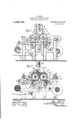
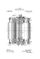
In the accompanying drawings, Figure 1.
represents a sideelevation-of my improved f machine for doubling fabrics, Fig. 2 is a vertical longitudinalsection ofthe sameon line. 2, 2, Fig. 3, and Fig.'3 is. a planview of the improved machine.V j
Similar letters of reference' indicate cor.
responding parts throughout the-figures,
Referringto-the drawings,- a, al are" two tubular 'rolls which are heatedby meansof live steam admitted to theinterior .of the rolls by steam supply-pipes?) connected withl one end of the 'rolls and'carried oi suitable exhaust-pipes 1 at the same-end. 'The `heated roll a is supported in stationary bearings ofa sup orting 'frame f, 'while the heated roll a?. 1s SUPPOrted Yin` s of horizontally adj-ustahleslide-re'sts 1i which. are guided on the frmef, so that the roll' al. cui be adjustednlor Ito-or away from the stationary roll a for providing for.'l
theA different thicknesses of thefabricsto be united. The' adjustment of the' movable roll a? is accomplished ley-means of screws d1 opposite direction toy veach other from a, driving shaft s, Awhich is supported in suitable bearings in the side-standards of the frame f blow the rolls, and intermediate driving gear-wheels g, g5 andgear-wheels l g2, g3 on the rolls a, a?. .The two layers of fabric to be united are' wound up on reels the shafts of which v are supported in bracket-bearings e, el at opposite ends of the frame f and conducted over suitable guide-rods e2, 6 3 and adjustable tension-rolls e4, e5 to the' heated rolls a, 1,1 and then be` tween the same in downward direction over.
a guide-roller e to a suitable conveyer (not shown) by which .the doubled fabrics, after they are united by the lrolls a, al, are `con` rolls c4, e are adjustable by means or sliderests e7, e8 which .are acted upon by screws e having hand-wheels elo so asV to apply. a.
Aducted off. The bearings of the tensionregulated tension to both layers of fabric.'
Nearthe ends of the heated rolls a, a1.' are located vertical' abutment-s 7i, the lower ends .l
of which extend by arc-shaped tapering portions lIt" into the angular space between the irolls, the arc-shaped portions being arranged The close to the surface of the rolls. ments l1. are suspended by hangery rods k2 and screw'and jam `nuts k3 'from a trans"- verse yoke'y havingA yertical endlportions which are attached tothe side-standards of the frame' f," the .top-portion., being provided with Slots lagfor perm-ating the lateral ad j ustment of the hangerlevers kz ofthe abut` ments over the. rolls, either closer together waterproofcement that is supplied tothe lfabrics in thev trough' formed between one of the fabricsI passing over the roll a1, tl1ev lower portions 'of the abutments h andan .inclined doctor which is-"supported, ona
transverse'bar 1 .that isA connected by inclined screwosts i2 and. 4screw-nuts j! to an ar brac etsz'ifattached to the, inner `oriaway from each other,l according ;to the width' of 'the fabrics to bei-doubled. .-The abutments li., h? serve to hold 'the liquefiedv sidesgof 'the abutments', as shown clearly in Vio Fig. 2. The ends of the bar l and the ends ,to the fabrics in heated and liquid condition Vso as to be spread luniformly over the surface of the ingoing fabrics, and is then firmly united with the face-fabric and its backing fabric by the pressure exerted thereon during their passage between the heated rolls, the two layers, after being doubledup or united, being then conducted uit below the rolls by passing over the roller e* at the lower part of the .frame f'.
Below the rolls a, al and in contact with the lower circumference of the same are arranged scrapers Z, Z1 which extend across the `full 'length of the rolls, said AScrapers being held in close contact with the surface of the heated rolls so as to remove any traces of cement that should be' pressed through m1- nute openings or the meshes of the fabric,
onto the surface of the same, or that portion of the cement that should run over the edges of the fabric passing over the roll a1, so that the surface of the rolls is kept absolutely cleared of even the slightest traces of cement and thereby 'the surface of the doubled-up fabric kept perfectly clear vof cement. The Scrapers Z, Zl are supported on two pairs of hangers Z2 that are pivotally united at their upper ends and suspended from the vertical portions of the yoke y and riveted or otherwise attached at their lower ends to the extreme ends of the Scrapers Z. For preventing the bending of the Scrapers midway between their ends and holding them in contact with-the heated rolls throughout their length, supporting platesl n are employed which press on the underside of the Scrapers andwhich are adjustably supported bymeans of inclined screwposts n1 and screw-nuts ns en inclined brackets n2, the lower parts of said brackets being supported Yon angular bars n4 extending transversely between the upright side-standards of the frame f, as shown in Fig. 2. By
vadjusting the threaded posts n1 of the supporting plates fn. slightly higher or lower on the brackets a2, the middle portion of the Scrapers can be accurately adjusted to the lower surface of the heated rolls. The cement that is removed-by the Scrapers from the surface ofthe rolls is collected in a suitlable receptacle (not shown) 4at the lower part of the frame and returned from time to maaien time to the trough-shaped space between the trough-shaped space, which latter acts in the nature of a hopper for supplying the waterp proof cement to the fabrics to be doubled or united.
Any suitable fabrics may' be doubled by sure is exerted on thel fabrics as they are `passing through the rolls, they are uniformly doubled and at the same time dried to a considerable extent, so that no further artificial drying is necessary. The properly backed and doubled fabrics'are wound up on a reel and ready for immediate shipment and use.
Having thus described my invention, I claim as new and desire to secure by Letters Patent:
l. A machine for doubling-fabrics, comprising a pair of rotatory heated rolls, means for guiding two layers of fabric from opposite sides to and over said rolls, upright abutments at opposite ends of said rolls, the lower ends of which extend into the ves space between said rolls, means for suspending said abutments, and .an inclined doctor supported on said abutments in proximity to one of said rolls. l
2.l A machine for doubling fabrics, com: prising a pair of rotatory heated rolls, means for guiding two layers of fabrics from opposite sides to and over said heated rolls, upright abutments at the ends of saidheated rolls, whereof the lower ends extend into the space between said rolls, means for adjusting said abutments to the rolls,an inclined doctorsupported on said abutments in proximity to one of said heated rolls, and means for adjusting said doctor relatively to said heated roll.
3.0 A machine for doubling fabrics, comprising a' pair of rotatory heated rolls, means for guiding twovvlayers of fabric from opposite sides to and oversaid rolls, upright abutments having lower tapering ends extending between said heated rol s, a transverse yoke for suspending said abutments,
means for adjusting the abutments verti- .for adjusting the doctor relatively to said roll.
4. A machine for doubling fabrics, comable, means for guiding two layers of fa rics fronropposite sides to and over said :heated rolls, an inclined doctor arranged in proximity to one of said rolls, upright abutmentsat the ends of th heated rolls provided-with curved tapering portions at their lower ends, extending between said rolls, scrapesat the lower parts of the heated rolls, and means for holding the Scrapers in contact with the lower surface of said rolls.
5. A machine for-doubling fabrics, comprising a pair of rotatory heated rolls, one roll being stationary and the other adjustable, means for guiding two layers of fabrics toand over said heated rolls, an inclined doctor arranged in proximity to one of said rolls, npr ht abntments at the ends of the heated ro ls and extending downwardly between the same, Scrapers arranged in contact with the lower parts of the heated rolls, hanger-rods for supporting said Scrapers, and means for sup orting the Scrapers at an intermediate point of their length for'holding them tightly against the iower surface of the heated rolls.
6.*A machine -for doubling fabrics, comprising a pair of rotatory heated rolls, onev roll being stationary and the. other adjust- I able, means for guiding two layers of I'abrics from opposite sides to and over said heated rolls, an inclined doctor arranged in proximity to one of said rolls, upright ahntnients at the ends of the heated rolls extending between the saine, Scrapers contacting with the lower parts of the heated rolls, curved hangers attached to said scra pers and suspended at their upper ends, a transverse yoke for supportingthe upp'er ends of said hangers, and means for supporting the Scrapers at points ntermedately between their ends.
In testimony, that I clamvthe foregoing as my invention, I have signed my name 1n 45 presence of two suhscribin f witnesses.
ALB )RT LEISEL, Witnesses: v PAUL Gomer., \FANN1E Frsx.
Priority Applications (1)
| Application Number | Priority Date | Filing Date | Title |
|---|---|---|---|
| US56182110A US1042129A (en) | 1910-05-17 | 1910-05-17 | Machine for doubling fabrics. |
Applications Claiming Priority (1)
| Application Number | Priority Date | Filing Date | Title |
|---|---|---|---|
| US56182110A US1042129A (en) | 1910-05-17 | 1910-05-17 | Machine for doubling fabrics. |
Publications (1)
| Publication Number | Publication Date |
|---|---|
| US1042129A true US1042129A (en) | 1912-10-22 |
Family
ID=3110403
Family Applications (1)
| Application Number | Title | Priority Date | Filing Date |
|---|---|---|---|
| US56182110A Expired - Lifetime US1042129A (en) | 1910-05-17 | 1910-05-17 | Machine for doubling fabrics. |
Country Status (1)
| Country | Link |
|---|---|
| US (1) | US1042129A (en) |
Cited By (2)
| Publication number | Priority date | Publication date | Assignee | Title |
|---|---|---|---|---|
| US3236714A (en) * | 1962-10-09 | 1966-02-22 | Rogers Corp | Method of and apparatus for producing reinforced sheet material |
| US3382130A (en) * | 1964-05-15 | 1968-05-07 | Fr D Etiquetage Virey & Garnie | Device for preventing the fouling of labelling machines by the label glue |
-
1910
- 1910-05-17 US US56182110A patent/US1042129A/en not_active Expired - Lifetime
Cited By (2)
| Publication number | Priority date | Publication date | Assignee | Title |
|---|---|---|---|---|
| US3236714A (en) * | 1962-10-09 | 1966-02-22 | Rogers Corp | Method of and apparatus for producing reinforced sheet material |
| US3382130A (en) * | 1964-05-15 | 1968-05-07 | Fr D Etiquetage Virey & Garnie | Device for preventing the fouling of labelling machines by the label glue |
Similar Documents
| Publication | Publication Date | Title |
|---|---|---|
| US687481A (en) | Machine for applying varnish, &c. | |
| US1402020A (en) | Laundry apparatus | |
| US1480348A (en) | Fabric-printing machine | |
| US778709A (en) | Painting-machine. | |
| US595669A (en) | chadwick | |
| US1799002A (en) | Knife-coating machine | |
| US399544A (en) | manahan | |
| JP7778912B2 (en) | Embossing Equipment | |
| US448873A (en) | Hermann bormann | |
| US727373A (en) | Paper-damping machine. | |
| US307130A (en) | Bronzing-machine | |
| US451011A (en) | Gumming-machine | |
| US532172A (en) | Machine for | |
| US664055A (en) | Paper-damping machine. | |
| US1133440A (en) | Machine for doubling fabrics. | |
| US483738A (en) | fisher | |
| US734949A (en) | Machine for coating sun-print paper. | |
| US350899A (en) | Nag-el | |
| US1258840A (en) | Apparatus for sizing paper. | |
| US745353A (en) | Hide-working machine. | |
| US423593A (en) | Machine foe | |
| US1154874A (en) | Coating apparatus. | |
| US263998A (en) | William h | |
| US524276A (en) | Machine for inking ribbons for type-writer machines | |
| US478236A (en) | Machine for waxing velvets |