US10419681B2 - Variable field of view multi-imager - Google Patents
Variable field of view multi-imager Download PDFInfo
- Publication number
- US10419681B2 US10419681B2 US15/334,473 US201615334473A US10419681B2 US 10419681 B2 US10419681 B2 US 10419681B2 US 201615334473 A US201615334473 A US 201615334473A US 10419681 B2 US10419681 B2 US 10419681B2
- Authority
- US
- United States
- Prior art keywords
- imagers
- view
- field
- selected field
- imager assembly
- Prior art date
- Legal status (The legal status is an assumption and is not a legal conclusion. Google has not performed a legal analysis and makes no representation as to the accuracy of the status listed.)
- Active, expires
Links
Images


Classifications
-
- H04N5/23296—
-
- H—ELECTRICITY
- H04—ELECTRIC COMMUNICATION TECHNIQUE
- H04N—PICTORIAL COMMUNICATION, e.g. TELEVISION
- H04N23/00—Cameras or camera modules comprising electronic image sensors; Control thereof
- H04N23/60—Control of cameras or camera modules
- H04N23/69—Control of means for changing angle of the field of view, e.g. optical zoom objectives or electronic zooming
-
- H—ELECTRICITY
- H04—ELECTRIC COMMUNICATION TECHNIQUE
- H04N—PICTORIAL COMMUNICATION, e.g. TELEVISION
- H04N23/00—Cameras or camera modules comprising electronic image sensors; Control thereof
- H04N23/45—Cameras or camera modules comprising electronic image sensors; Control thereof for generating image signals from two or more image sensors being of different type or operating in different modes, e.g. with a CMOS sensor for moving images in combination with a charge-coupled device [CCD] for still images
-
- H—ELECTRICITY
- H04—ELECTRIC COMMUNICATION TECHNIQUE
- H04N—PICTORIAL COMMUNICATION, e.g. TELEVISION
- H04N23/00—Cameras or camera modules comprising electronic image sensors; Control thereof
- H04N23/50—Constructional details
- H04N23/51—Housings
-
- H—ELECTRICITY
- H04—ELECTRIC COMMUNICATION TECHNIQUE
- H04N—PICTORIAL COMMUNICATION, e.g. TELEVISION
- H04N23/00—Cameras or camera modules comprising electronic image sensors; Control thereof
- H04N23/50—Constructional details
- H04N23/54—Mounting of pick-up tubes, electronic image sensors, deviation or focusing coils
-
- H—ELECTRICITY
- H04—ELECTRIC COMMUNICATION TECHNIQUE
- H04N—PICTORIAL COMMUNICATION, e.g. TELEVISION
- H04N23/00—Cameras or camera modules comprising electronic image sensors; Control thereof
- H04N23/50—Constructional details
- H04N23/55—Optical parts specially adapted for electronic image sensors; Mounting thereof
-
- H—ELECTRICITY
- H04—ELECTRIC COMMUNICATION TECHNIQUE
- H04N—PICTORIAL COMMUNICATION, e.g. TELEVISION
- H04N23/00—Cameras or camera modules comprising electronic image sensors; Control thereof
- H04N23/60—Control of cameras or camera modules
- H04N23/698—Control of cameras or camera modules for achieving an enlarged field of view, e.g. panoramic image capture
-
- H04N5/2252—
-
- H04N5/2253—
-
- H04N5/2254—
-
- H04N5/2258—
-
- H04N5/23238—
Definitions
- the present invention relates to image capture technology, specifically to pan, tilt, and zoom (“PTZ”) cameras and panoramic cameras.
- PTZ pan, tilt, and zoom
- PTZ cameras allow for the view of an image to be adjusted via pan, tilt, horizon, or zoom functions.
- PTZ cameras can be used in various environments and for various applications e.g., television or movie studios, sporting events, and for surveillance or security applications.
- panoramic cameras are often static.
- Panoramic cameras stitch together video output from multiple individual imagers side-by-side to produce the panoramic image, which has a wide aspect ratio.
- Panoramic cameras often do not possess zooming capabilities. The panoramic image will break apart as the field of view decreases in a zoom-out function or will overlap images as the field of view increases in a zoom-in function.
- the invention provides a multi-imager assembly including a plurality of imagers operable to produce a composite image, with each of the plurality of imagers having optical zoom capability such that each of the plurality of imagers has a variable field of view.
- a chassis movably supports the plurality of imagers.
- a drive assembly is operable to move the plurality of imagers while supported by the chassis.
- a controller is operable to coordinate movement of the plurality of imagers based at least in part upon the variable field of view of each of the plurality of imagers to produce the composite image.
- the invention provides a method of providing a composite image with a variable field of view.
- the method includes providing a plurality of imagers operable to produce a composite image, with each of the plurality of imagers having optical zoom capability such that each of the plurality of imagers has a variable field of view.
- the method further includes providing a chassis movably supporting the plurality of imagers and providing a drive assembly operable to move the chassis. Additionally, the method coordinates movement of the plurality of imagers based at least in part upon the variable field of view of each of the plurality of imagers to produce the composite image.
- FIG. 1 is a perspective view of an exemplary multi-imager assembly embodying the invention.
- FIG. 2 is an exploded isometric view of the exemplary multi-imager assembly of FIG. 1 .
- FIG. 3 is a schematic view of a configuration for a controller coordinating the movement of an exemplary multi-imager assembly.
- FIG. 4A is a schematic of a field of view for an exemplary multi-imager assembly having an odd number of imagers.
- FIG. 4B is a schematic of a field of view for an exemplary multi-imager assembly having an even number of imagers.
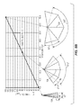
- FIG. 5A is a graphical depiction of an exemplary multi-imager assembly having three imagers.
- FIG. 5B is a graphical depiction of an exemplary multi-imager assembly having four imagers.
- FIGS. 1-5B illustrate and describe a multi-imager assembly 1 capable of producing a composite or panoramic image with an optical zoom capability.
- the multi-imager assembly 1 makes adjustments to a plurality of imagers 2 , 4 , 6 , 8 in a coordinated manner to maintain a seamless variable field of view such that the panoramic image does not break apart when the field of view decreases i.e., a zoom-out function, or wastes imager coverage as the field of view increases i.e., a zoom-in function.
- the optical zoom capability is implemented by driving the plurality of imagers 2 , 4 , 6 , 8 such that each of the plurality of imagers 2 , 4 , 6 , 8 is capable of having a variable field of view.
- the plurality of imagers 2 , 4 , 6 , 8 operate and move together to produce the composite image with each of the plurality of imagers 2 , 4 , 6 , 8 having optical zoom capability such that each of the plurality of imagers 2 , 4 , 6 , 8 has a variable field of view.
- the variable field of view panoramic image of the multi-imager assembly 1 is produced by utilizing equations, which are described in detail below, that relate the number of individual imagers and their associated field of views with the rotational ratios of the angle adjustment required to align an optical plane of symmetry of each individual imager through the optical zooming adjustment.
- FIGS. 1 and 2 illustrate an exemplary embodiment of a multi-imager assembly 1 including a plurality of imagers 2 , 4 , 6 , 8 .
- the multi-imager assembly 1 can have a varied number of imagers.
- the multi-imager assembly 1 can have four individual imagers 2 , 4 , 6 , 8 as shown in FIGS. 1 and 2 .
- other exemplary embodiments can have two imagers, such as the top pair of imagers 2 and 4 or the bottom pair of imagers 6 and 8 shown in FIGS. 1 and 2 .
- the multi-imager assembly 1 further includes a chassis 12 .
- the chassis 12 includes shafts 14 , 16 , apertures 20 , 22 having two pairs of countersinks 24 , 26 , and a tilt plate 28 .
- the chassis 12 is pivotably coupled to a mounting member 32 having through holes 34 , 36 .
- the mounting member 32 can be movably coupled or fixed to a fixture (not shown) (e.g., a pole, wall, ceiling, etc.) to provide support to the multi-imager assembly 1 .
- the through hole 34 pivotably receives the shaft 14 and the through hole 36 pivotably receives the shaft 16 such that the chassis 12 tilts about a horizontal axis A 1 of the multi-imager assembly 1 .
- An actuator can be coupled to the mounting member 32 to drive the tilt plate 28 of the chassis 12 to tilt the chassis 12 about the horizontal axis A 1 .
- a bearing member (not shown) is positioned between the mounting member 32 and the fixture.
- another actuator (not shown) can be coupled to the mounting member 32 to drive the mounting member 32 relative to the bearing member allowing for the chassis 12 to pan about a vertical axis A 2 of the multi-imager assembly 1 .
- the multi-imager assembly 1 further includes a drive assembly 40 .
- the drive assembly 40 includes a plurality of gears 44 , brackets 46 , and a motor 48 .
- the plurality of gears 44 includes a first pair of gears 52 , 54 and a second pair of gears 56 , 58 .
- Each of the first pair of gears 52 , 54 includes include a hub 62 , through holes 64 , a first set of teeth 66 , a second set of teeth 68 , and an aperture 70 .
- the first set of teeth 66 is formed in a distal end of the gears 52 , 54
- the second set of teeth 68 is formed on an arcuate projection extending from the face of the gears 52 , 54 in a same direction as the hub 62 extends.
- Each of the second pair of gears 56 , 58 includes a hub 72 , through holes 74 , teeth 76 , and an aperture 78 .
- the hub 62 of the gear 52 and the hub 72 of the gear 58 are rotatably received into the pair of countersinks 26 of the chassis 12 .
- the hub 62 of the gear 54 and the hub 72 of the gear 56 are rotatably received into the pair of countersinks 24 of the chassis 12 .
- the hubs 62 and 72 and the pair of countersinks 24 and 26 each can have re-entrant ball races (not shown) configured to receive bearing balls.
- a center axis of the ball races of the hubs 62 and 72 and a center axis of the countersinks 24 and 26 would be initially mis-aligned for assembly. This allows for bearing balls to be introduced into the ball races on one side of either the hubs 62 and 72 or the countersinks 24 and 26 .
- the ball races would then be aligned so that the center axes of the ball races were coincident.
- the bearing balls would be tangentially distributed evenly through each of the ball races, and can be held in this position by a bearing ball cage.
- This exemplary embodiment allows for the hubs 62 and 72 to be rotatably received in the countersinks 24 and 26 of the chassis 12 .
- other exemplary embodiments may be used to achieve the function described above (e.g., press or snap fitting the hubs into standard bearings on the countersinks of the chassis).
- the brackets 46 each include an imager attachment portion 82 having through holes 84 and a gear attachment portion 88 having through holes 90 with corresponding countersinks 93 .
- the imager attachment portion 82 couples the brackets 46 to the plurality of imagers 2 , 4 , 6 , 8 by receiving fasteners (not shown) in the through holes 84 .
- the fasteners are then fastened into each of the plurality of imagers 2 , 4 , 6 , 8 to secure the plurality of imagers to the multi-imager assembly 1 .
- fasteners 92 e.g., screws
- the fasteners 92 are then tightened such that the head of each of the fasteners 92 is in communication with the countersink 93 of each through hole 90 to couple the plurality of imagers 2 , 4 , 6 , 8 to the drive assembly 40 .
- the imager 2 is secured to the gear 56 by its bracket 46
- the imager 4 is secured to the gear 52 by its bracket 46
- the imager 6 is secured to the gear 54 by its bracket 46
- the imager 8 is secured to the gear 58 by its bracket 46 .
- the motor 48 includes a worm gear 96 on its output pinion and an attachment portion 98 having through holes 100 .
- the attachment portion 98 is configured to couple the motor 48 to the multi-imager assembly 1 by receiving fasteners (not shown) in the through holes 100 .
- the motor 48 can be coupled to the chassis 12 .
- the motor 48 is coupled to the multi-imager assembly 1 adjacent to one of second pair of gears 56 such that the worm gear 96 intermeshes with the teeth 76 of the gear 56 .
- the motor 48 is coupled to the multi-imager assembly adjacent to the gear 58 such that the worm gear 96 intermeshes with the teeth 76 of the gear 58 .
- Other embodiments may use more motors to drive each of the imagers individually.
- the drive assembly 40 having the plurality of gears 44 is configured to drive movement of the plurality of imagers 2 , 4 , 6 , 8 .
- the first pair of gears 52 , 54 and the second pair of gears 56 , 58 have an intermeshing relation to rotatably drive each of the plurality of imagers 2 , 4 , 6 , 8 about a respective vertical axis A 3 .
- the motor 48 rotates the worm gear 96 , which has an intermeshing relation to the teeth 76 of gear 56 , to drive the gear 56 providing the rotational movement of imager 2 .
- the rotational movement of the gear 56 having teeth 76 which have an intermeshing relation to the first set of teeth 66 of the gear 52 , drives the gear 52 providing rotational movement of imager 4 .
- the gear 52 and the gear 54 have the symmetrical second set of intermeshing teeth 68 such that motion is transferred from the gear 52 to the gear 54 , thereby providing rotational movement of imager 6 . Therefore, the intermeshing second set of teeth 68 transmits rotation between the upper pair of images 2 , 4 and the lower pair of imagers 6 , 8 .
- the first set of teeth 66 of gear 54 which have an intermeshing relation to the teeth 76 of the gear 58 , drive the gear 58 providing rotational movement of the imager 8 .
- the first pair of gears 52 , 54 has seventy-two teeth and the second pair of gears 56 , 58 has twenty-four teeth in each of the tooth sets 66 and 68 .
- This configuration produces a 3-to-1 gear ratio for the four imagers 2 , 4 , 6 , 8 and allows all four imagers 2 , 4 , 6 , 8 to simultaneously pivot about the respective axes A 3 symmetrically. Relative field of view spacing is maintained for each of the plurality of imagers 2 , 4 , 6 , 8 to produce the seamless composite or panoramic view.
- each of the plurality of imagers 2 , 4 , 6 , 8 includes a lens portion 104 and an attachment portion 106 .
- the lens portion 104 includes a lens 110 at a distal end of each of the plurality of imagers 2 , 4 , 6 , 8 .
- the lens 110 is adjustable to produce the variable field of view.
- the lens portion 104 further includes a lens actuator 114 , as shown schematically in FIG. 3 , to drive the lens 110 to produce the variable field of view.
- the attachment portion 106 is configured to couple each of the plurality of imagers 2 , 4 , 6 , 8 to the respective brackets 46 , as described above.
- the exemplary multi-imager assembly 1 shown in FIGS. 1 and 2 and described above can also be positioned inside of a dome structure 116 as shown in the schematic view of FIG. 3 .
- the dome structure 116 could cover and conceal the lens 110 of each of the plurality of imagers 2 , 4 , 6 , 8 , which is a common configuration for security camera assemblies.
- FIG. 3 also schematically illustrates a controller 120 that coordinates the movement of the plurality of imagers 2 , 4 , 6 , 8 to produce the composite image.
- the controller 120 can be programmed in an open loop, in which the movements of the multi-imager assembly 1 are calibrated in a factory setting.
- the controller 120 can be programmed in a closed loop, in which the controller 120 would receive feedback from a position sensor on either the lens 110 or on each of the plurality of imagers 2 , 4 , 6 , 8 .
- the controller 120 controls both the motor 48 of the drive assembly 40 and the lens actuators 114 of each of the plurality of imagers 2 , 4 , 6 , 8 .
- the controller 120 sends signals to produce angular actuations in increments of size (“delta”). Both the motor 48 and the lens actuators 114 are driven within a motion of a prescribed range.
- the lens portion 104 can include a position measurement device to report a position value to the controller 120
- the drive assembly 40 can include a similar position measurement device.
- the lens actuator 114 zooms the lens of the imager between a wide field of view angle (“wide”) and a narrow field of view angle (“tele”) with the wide and tele field of view angles constituting an upper and lower limit of the lens field of view, respectively.
- the controller 120 is calibrated to assign angular increments based on the difference between the wide and tele field of view angles, divided by the controller delta.
- the lens actuator 114 can then provide any field of view angle between these two limits based on a position data feed to the controller 120 .
- the motor 48 of the drive assembly 40 can rotate the plurality of imagers 2 , 4 , 6 , 8 between two prescribed angular limits, panoramic “wide” and panoramic “tele.”
- the controller 120 is also calibrated to assign angular drive assembly increments based on the difference between panoramic wide and panoramic tele, divided by the controller delta. In this manner, the motor 48 can achieve any angle between those two limits based on a data feed to the controller 120 .
- the composite or panoramic image is produced and maintained by use of the following algorithms embedded in software that operates the controller 120 , which coordinates the movement of the plurality of imagers 2 , 4 , 6 , 8 to produce the composite image as described above. These equations maintain a uniform overall aspect ratio of the composite image such that the lens 110 of each of the plurality of imagers 2 , 4 , 6 , 8 has the same varifocal characteristics, which are driven by the lens actuator 114 based on the data feed to the controller 120 .
- the field of view angle at the tele position is FoV TELE and the field of view angle at the wide position is FoV WIDE
- the following field of view function can be defined where the variable x can be any value between 0 and 1, including being equal to 0 and 1:
- variable x is proportional to the optical zoom value of the lenses 110 of each of the plurality of imagers 2 , 4 , 6 , 8 . If the optical zoom value is linearly proportional to the field of view, these linear imager equations would define how the field of view can vary with the optical zoom value of the lens 110 . In other exemplary embodiments, if the lenses 110 of the plurality of imagers 2 , 4 , 6 , 8 are configured with a non-linear optical zoom function, then additional terms (not shown) would be added to the above linear equations to replicate the non-linear behavior of the lenses 110 .
- the relative position of each individual imager's field of view within the overall panoramic view will be located by the individual field of view centerline for each of the plurality of imagers 2 , 4 , 6 , 8 .
- the plurality of imagers' 2 , 4 , 6 , 8 lenses 110 produce a continuous optically symmetric field of view, so that the center of the individual field of view coincides with the optical centerline of the imager lens 110 at all optical zoom values. If the imager lenses 110 are not continuously optically symmetric (i.e. asymmetric) at all zoom values, then additional terms would be added to the below equations to reflect the effects of this optical asymmetry.
- the drive assembly 40 of the multi-imager assembly 1 causes the centerline angles of each imager's field of view to vary by rotational translation to ensure a properly interconnected panoramic field of view. It is understood that, due to mechanism design constraints, the imager centerlines do not need to be exactly coincident.
- the scenes being viewed by the multi-imager assembly 1 are at much larger distances than the separation distances between the plurality of imagers 2 , 4 , 6 , 8 within the multi-imager assembly 1 , and thus the imager separation distances within the multi-imager assembly 1 have a very small relative effect on the panoramic view and can therefore be neglected.
- the panoramic field of view has a centerline 124 that is considered as a primary reference, with the various individual imager fields of view symmetrically disposed on either side of the panoramic field of view centerline 124 , as shown in FIGS. 4A-5B .
- the governing relationships between the individual imager centerlines and the panoramic field of view centerline 124 depend on whether an odd or even number of individual imagers are utilized in creating the panoramic view. With an odd number of optically symmetric individual imagers, the panoramic field of view centerline 124 always coincides with the field of view centerline of the center individual imager. With an even number of optically symmetric individual imagers, the panoramic field of view centerline 124 never coincides with any individual imager's field of view centerline.
- (n ⁇ 1) is the inverse slope of the relationship, and determines the mechanism rotational ratio needed to achieve a continuously interconnected panoramic view.
- the inverse slope is 1 and therefore the mechanism ratio is 1 between the centerlines of those two individual imager centerlines.
- the inverse slope is 2 and therefore the mechanism ratio is 2 between the centerlines of those two individual imager centerlines.
- the calculation is performed first with n set at the value for the set closest to the panoramic image centerline, and then the calculation is performed again with n set at the value of the set located in the next closest position relative to the panoramic image centerline.
- the inverse slope is 1, and therefore the mechanism ratio is 1 between the centerlines of those two individual imagers' centerlines closest to the panoramic field of view centerline 124 .
- the mechanism ratio is 3 between the centerlines of those two individual imagers' centerlines that are on the outside of the four-imager multi-imager assembly (i.e. the multi-imager assembly 1 shown in FIGS. 1 and 2 ), the next closest position relative to the panoramic image centerline 124 .
- a multi-imager assembly can be designed to support any number of imagers using the relationship described above. For example, FIG.
- FIGS. 4A and 4B illustrate a schematic field of view for an odd number of imagers, specifically three imagers.
- FIG. 4B illustrates a schematic field of view for an even number of imagers, specifically four imagers.
- the x-axis represents the field of view of the individual imager
- the y-axis represents a resulting panoramic symmetric angle ⁇ .
- the graphical representation of FIGS. 5A and 5B is based on the assumption of a basic interconnection of the individual imager's fields of view to form the panoramic field of view. There are some reasons, among others, to form the panoramic view from only a portion of the individual imager's field of view.
Landscapes
- Engineering & Computer Science (AREA)
- Multimedia (AREA)
- Signal Processing (AREA)
- Human Computer Interaction (AREA)
- Studio Devices (AREA)
- Stereoscopic And Panoramic Photography (AREA)
Abstract
Description
FoVIMAGER(x)=(FoVWIDE−FoVTELE)x+FoVTELE
at x=0,FoVIMAGER(0)=(FoVWIDE−FoVTELE)*0+FoVTELE=FoVTELE
at x=0.5,FoVIMAGER(0.5)=(FoVWIDE+FoVTELE)/2
at x=1,FoVIMAGER(1)=(FoVWIDE−FoVTELE)*1+FoVTELE=FoVWIDE.
The variable x is proportional to the optical zoom value of the
ϕ(x,n)=(n−1)FoVIMAGER(x).
Accordingly, (n−1) is the inverse slope of the relationship, and determines the mechanism rotational ratio needed to achieve a continuously interconnected panoramic view. For n=2, the inverse slope is 1 and therefore the mechanism ratio is 1 between the centerlines of those two individual imager centerlines. For n=3, the inverse slope is 2 and therefore the mechanism ratio is 2 between the centerlines of those two individual imager centerlines. When there are multiple sets of individual imager pairs symmetrically disposed on either side of the
| (npairA − 1) * | ||||
| n | npair | ϕ (x) | (npairB − 1) * ϕ (x) | (npairC − 1) * ϕ (x) |
| 2 | 2 | 1 ϕ (x | N/A | N/ |
| 3 | 3 | 2 ϕ (x) | N/A | N/ |
| 4 | 4 | 3 ϕ (x) | N/A | N/ |
| 5 | 3, 5 | 2 ϕ (x) | 4 ϕ (x) | N/ |
| 6 | 4, 6 | 3 ϕ (x) | 5 ϕ (x) | N/A |
| 7 | 3, 5, 7 | 2 ϕ (x) | 4 ϕ (x) | 6 ϕ (x) |
A multi-imager assembly can be designed to support any number of imagers using the relationship described above. For example,
FoVIMAGER,SCALED(x)(1−p)FoVIMAGER.
The above equation allows for the scaling of the individual field of view of each of the plurality of
Claims (19)
Priority Applications (1)
| Application Number | Priority Date | Filing Date | Title |
|---|---|---|---|
| US15/334,473 US10419681B2 (en) | 2016-10-26 | 2016-10-26 | Variable field of view multi-imager |
Applications Claiming Priority (1)
| Application Number | Priority Date | Filing Date | Title |
|---|---|---|---|
| US15/334,473 US10419681B2 (en) | 2016-10-26 | 2016-10-26 | Variable field of view multi-imager |
Publications (2)
| Publication Number | Publication Date |
|---|---|
| US20180115720A1 US20180115720A1 (en) | 2018-04-26 |
| US10419681B2 true US10419681B2 (en) | 2019-09-17 |
Family
ID=61970126
Family Applications (1)
| Application Number | Title | Priority Date | Filing Date |
|---|---|---|---|
| US15/334,473 Active 2037-03-09 US10419681B2 (en) | 2016-10-26 | 2016-10-26 | Variable field of view multi-imager |
Country Status (1)
| Country | Link |
|---|---|
| US (1) | US10419681B2 (en) |
Cited By (1)
| Publication number | Priority date | Publication date | Assignee | Title |
|---|---|---|---|---|
| US10656503B2 (en) * | 2016-08-17 | 2020-05-19 | Sz Dji Osmo Technology Co., Ltd. | Gimbal control |
Families Citing this family (3)
| Publication number | Priority date | Publication date | Assignee | Title |
|---|---|---|---|---|
| US10388133B1 (en) * | 2018-02-26 | 2019-08-20 | Panasonic Intellectual Property Management Co., Ltd. | Surveillance camera |
| CN110971788B (en) * | 2018-09-28 | 2022-06-21 | 中国科学院长春光学精密机械与物理研究所 | An infinite rotating large field of view scanning imaging system and control system |
| CN111491094B (en) * | 2019-01-28 | 2021-08-31 | 北京小米移动软件有限公司 | Camera module and terminal |
Citations (21)
| Publication number | Priority date | Publication date | Assignee | Title |
|---|---|---|---|---|
| US20040062541A1 (en) * | 2002-07-05 | 2004-04-01 | Tetsurou Kajino | Camera rotation device |
| US6850025B1 (en) * | 2000-06-30 | 2005-02-01 | Sensormatic Electronics Corporation | Integrated enclosure and controller for video surveillance camera |
| US20070126863A1 (en) * | 2005-04-07 | 2007-06-07 | Prechtl Eric F | Stereoscopic wide field of view imaging system |
| US20070235648A1 (en) * | 2004-09-09 | 2007-10-11 | Teich Andrew C | Multiple camera systems and methods |
| US20080024390A1 (en) * | 2006-07-31 | 2008-01-31 | Henry Harlyn Baker | Method and system for producing seamless composite images having non-uniform resolution from a multi-imager system |
| US7440027B2 (en) | 2004-03-12 | 2008-10-21 | Robert Bosch Gmbh | Mounting assembly for camera |
| US20100033577A1 (en) | 2008-08-05 | 2010-02-11 | I2C Technologies, Ltd. | Video surveillance and remote monitoring |
| US7680192B2 (en) | 2003-07-14 | 2010-03-16 | Arecont Vision, Llc. | Multi-sensor panoramic network camera |
| US20100238262A1 (en) * | 2009-03-23 | 2010-09-23 | Kurtz Andrew F | Automated videography systems |
| US20100296802A1 (en) * | 2009-05-21 | 2010-11-25 | John Andrew Davies | Self-zooming camera |
| US20120098927A1 (en) * | 2009-06-29 | 2012-04-26 | Bosch Security Systems Inc. | Omni-directional intelligent autotour and situational aware dome surveillance camera system and method |
| US8279283B2 (en) | 2005-11-18 | 2012-10-02 | Utc Fire & Security Americas Corporation, Inc. | Methods and systems for operating a video surveillance system |
| US8325229B2 (en) | 2008-11-26 | 2012-12-04 | Robert Bosch Gmbh | Camera having a slip ring and pan-tilt mechanism |
| US20130044181A1 (en) | 2010-05-14 | 2013-02-21 | Henry Harlyn Baker | System and method for multi-viewpoint video capture |
| US20140139623A1 (en) | 2009-01-05 | 2014-05-22 | Duke University | Panoramic multi-scale imager and method therefor |
| US20150009350A1 (en) | 2009-09-22 | 2015-01-08 | Altia Systems Inc | Multi-Imager Video Camera with Frame-by-Frame View Switching |
| US9094540B2 (en) | 2012-12-13 | 2015-07-28 | Microsoft Technology Licensing, Llc | Displacing image on imager in multi-lens cameras |
| US9124801B2 (en) | 2012-07-26 | 2015-09-01 | Omnivision Technologies, Inc. | Image processing system and method using multiple imagers for providing extended view |
| US20150304559A1 (en) | 2014-03-28 | 2015-10-22 | Kogeto, Inc. | Multiple camera panoramic image capture apparatus |
| US9232155B1 (en) | 2012-05-25 | 2016-01-05 | Altia Systems Inc. | Automated alignment adjustment for multiple imager based video systems |
| US9819863B2 (en) * | 2014-06-20 | 2017-11-14 | Qualcomm Incorporated | Wide field of view array camera for hemispheric and spherical imaging |
Family Cites Families (2)
| Publication number | Priority date | Publication date | Assignee | Title |
|---|---|---|---|---|
| US7252774B2 (en) * | 2005-06-08 | 2007-08-07 | International Business Machines Corporation | Selective chemical etch method for MRAM soft layers |
| US9819683B2 (en) * | 2016-03-15 | 2017-11-14 | Bank Of America Corporation | Automated control of technology resources |
-
2016
- 2016-10-26 US US15/334,473 patent/US10419681B2/en active Active
Patent Citations (22)
| Publication number | Priority date | Publication date | Assignee | Title |
|---|---|---|---|---|
| US6850025B1 (en) * | 2000-06-30 | 2005-02-01 | Sensormatic Electronics Corporation | Integrated enclosure and controller for video surveillance camera |
| US20040062541A1 (en) * | 2002-07-05 | 2004-04-01 | Tetsurou Kajino | Camera rotation device |
| US7680192B2 (en) | 2003-07-14 | 2010-03-16 | Arecont Vision, Llc. | Multi-sensor panoramic network camera |
| US7440027B2 (en) | 2004-03-12 | 2008-10-21 | Robert Bosch Gmbh | Mounting assembly for camera |
| US20070235648A1 (en) * | 2004-09-09 | 2007-10-11 | Teich Andrew C | Multiple camera systems and methods |
| US20070126863A1 (en) * | 2005-04-07 | 2007-06-07 | Prechtl Eric F | Stereoscopic wide field of view imaging system |
| US8279283B2 (en) | 2005-11-18 | 2012-10-02 | Utc Fire & Security Americas Corporation, Inc. | Methods and systems for operating a video surveillance system |
| US7855752B2 (en) | 2006-07-31 | 2010-12-21 | Hewlett-Packard Development Company, L.P. | Method and system for producing seamless composite images having non-uniform resolution from a multi-imager system |
| US20080024390A1 (en) * | 2006-07-31 | 2008-01-31 | Henry Harlyn Baker | Method and system for producing seamless composite images having non-uniform resolution from a multi-imager system |
| US20100033577A1 (en) | 2008-08-05 | 2010-02-11 | I2C Technologies, Ltd. | Video surveillance and remote monitoring |
| US8325229B2 (en) | 2008-11-26 | 2012-12-04 | Robert Bosch Gmbh | Camera having a slip ring and pan-tilt mechanism |
| US20140139623A1 (en) | 2009-01-05 | 2014-05-22 | Duke University | Panoramic multi-scale imager and method therefor |
| US20100238262A1 (en) * | 2009-03-23 | 2010-09-23 | Kurtz Andrew F | Automated videography systems |
| US20100296802A1 (en) * | 2009-05-21 | 2010-11-25 | John Andrew Davies | Self-zooming camera |
| US20120098927A1 (en) * | 2009-06-29 | 2012-04-26 | Bosch Security Systems Inc. | Omni-directional intelligent autotour and situational aware dome surveillance camera system and method |
| US20150009350A1 (en) | 2009-09-22 | 2015-01-08 | Altia Systems Inc | Multi-Imager Video Camera with Frame-by-Frame View Switching |
| US20130044181A1 (en) | 2010-05-14 | 2013-02-21 | Henry Harlyn Baker | System and method for multi-viewpoint video capture |
| US9232155B1 (en) | 2012-05-25 | 2016-01-05 | Altia Systems Inc. | Automated alignment adjustment for multiple imager based video systems |
| US9124801B2 (en) | 2012-07-26 | 2015-09-01 | Omnivision Technologies, Inc. | Image processing system and method using multiple imagers for providing extended view |
| US9094540B2 (en) | 2012-12-13 | 2015-07-28 | Microsoft Technology Licensing, Llc | Displacing image on imager in multi-lens cameras |
| US20150304559A1 (en) | 2014-03-28 | 2015-10-22 | Kogeto, Inc. | Multiple camera panoramic image capture apparatus |
| US9819863B2 (en) * | 2014-06-20 | 2017-11-14 | Qualcomm Incorporated | Wide field of view array camera for hemispheric and spherical imaging |
Non-Patent Citations (3)
| Title |
|---|
| Arecont Vision, AV12176DN <https://www.arecontvision.com/product/SurroundVideo+Omni+G2+Series/AV12176DN-08#KeyFeatures> Publicly available at least as early as Feb. 5, 2016. |
| Arecont Vision, AV20175DN <https://www.arecontvision.com/product/SurroundVideo+Omni+G2+Series/AV20175DN-28#KeyFeatures> Publicly available at least as early as Feb. 5, 2016. |
| Axis Communications, AXIS Q3709-PVE Network Camera <http://www.axis.com/ie/en/products/axis-q3709-pve> Publicly available at least as early as Feb. 5, 2016. |
Cited By (2)
| Publication number | Priority date | Publication date | Assignee | Title |
|---|---|---|---|---|
| US10656503B2 (en) * | 2016-08-17 | 2020-05-19 | Sz Dji Osmo Technology Co., Ltd. | Gimbal control |
| US11175569B2 (en) | 2016-08-17 | 2021-11-16 | Sz Dji Osmo Technology Co., Ltd. | Gimbal control |
Also Published As
| Publication number | Publication date |
|---|---|
| US20180115720A1 (en) | 2018-04-26 |
Similar Documents
| Publication | Publication Date | Title |
|---|---|---|
| US10419681B2 (en) | Variable field of view multi-imager | |
| EP3596543B1 (en) | Camera with panoramic scanning range | |
| EP2556654B1 (en) | Apparatus and method for capturing images | |
| US20060023074A1 (en) | Omni-directional camera with calibration and up look angle improvements | |
| EP3573324B1 (en) | Camera assembly and electronic apparatus | |
| KR20210022973A (en) | Multi camera apparatus and photography system having the same | |
| CN101636769A (en) | Method and system for video surveillance system motor overcurrent protection | |
| US20090290033A1 (en) | Systems and methods of creating a virtual window | |
| JPH10233950A (en) | Electronic zoom image input system | |
| JPH0983841A (en) | Structure for universal head for television camera and panning tilt camera | |
| JP2012088396A (en) | Surveillance camera | |
| KR101889275B1 (en) | Single-frame stereoscopic camera | |
| CN118764717A (en) | Auxiliary lens-based pan/tilt camera system and control method | |
| CN109729247B (en) | Video pixel control array camera device | |
| WO2017206424A1 (en) | Pan-tilt and photographing apparatus comprising pan-tilt | |
| US11831851B1 (en) | Multiple camera sensor system | |
| JPH02260890A (en) | Stereoscopic camera device | |
| JP4933086B2 (en) | Multifocal camera imaging unit mounting structure | |
| JP4235683B2 (en) | Electronic zoom image input method | |
| CN115996305A (en) | A camera and monitoring equipment | |
| JP7515265B2 (en) | Image capture device, image processing device control method, and image capture system | |
| WO2006093387A1 (en) | Panorama watch camera apparatus and the deferment unit thereof | |
| US20260089382A1 (en) | Versatile Perspective Control | |
| CN223067155U (en) | PTZ camera system based on auxiliary lens | |
| KR200256732Y1 (en) | a monitor camera |
Legal Events
| Date | Code | Title | Description |
|---|---|---|---|
| AS | Assignment |
Owner name: BOSCH SECURITY SYSTEMS, INC., NEW YORK Free format text: ASSIGNMENT OF ASSIGNORS INTEREST;ASSIGNOR:JONES, THEODORE LEROY;REEL/FRAME:040139/0293 Effective date: 20161019 Owner name: ROBERT BOSCH GMBH, GERMANY Free format text: ASSIGNMENT OF ASSIGNORS INTEREST;ASSIGNOR:JONES, THEODORE LEROY;REEL/FRAME:040139/0293 Effective date: 20161019 |
|
| STPP | Information on status: patent application and granting procedure in general |
Free format text: DOCKETED NEW CASE - READY FOR EXAMINATION |
|
| STPP | Information on status: patent application and granting procedure in general |
Free format text: NON FINAL ACTION MAILED |
|
| STPP | Information on status: patent application and granting procedure in general |
Free format text: NOTICE OF ALLOWANCE MAILED -- APPLICATION RECEIVED IN OFFICE OF PUBLICATIONS |
|
| STPP | Information on status: patent application and granting procedure in general |
Free format text: PUBLICATIONS -- ISSUE FEE PAYMENT VERIFIED |
|
| STCF | Information on status: patent grant |
Free format text: PATENTED CASE |
|
| MAFP | Maintenance fee payment |
Free format text: PAYMENT OF MAINTENANCE FEE, 4TH YEAR, LARGE ENTITY (ORIGINAL EVENT CODE: M1551); ENTITY STATUS OF PATENT OWNER: LARGE ENTITY Year of fee payment: 4 |
|
| AS | Assignment |
Owner name: GLAS TRUST CORPORATION LIMITED, UNITED KINGDOM Free format text: INTELLECTUAL PROPERTY SECURITY AGREEMENT;ASSIGNOR:BOSCH SECURITY SYSTEMS, LLC (FKA BOSCH SECURITY SYSTEMS, INC.);REEL/FRAME:073363/0729 Effective date: 20251027 |