US10418924B2 - Engine generator with a boosting circuit for starting an engine - Google Patents
Engine generator with a boosting circuit for starting an engine Download PDFInfo
- Publication number
- US10418924B2 US10418924B2 US15/938,734 US201815938734A US10418924B2 US 10418924 B2 US10418924 B2 US 10418924B2 US 201815938734 A US201815938734 A US 201815938734A US 10418924 B2 US10418924 B2 US 10418924B2
- Authority
- US
- United States
- Prior art keywords
- engine
- power converter
- converter circuit
- output terminal
- circuit
- Prior art date
- Legal status (The legal status is an assumption and is not a legal conclusion. Google has not performed a legal analysis and makes no representation as to the accuracy of the status listed.)
- Active
Links
Images


Classifications
-
- H—ELECTRICITY
- H02—GENERATION; CONVERSION OR DISTRIBUTION OF ELECTRIC POWER
- H02P—CONTROL OR REGULATION OF ELECTRIC MOTORS, ELECTRIC GENERATORS OR DYNAMO-ELECTRIC CONVERTERS; CONTROLLING TRANSFORMERS, REACTORS OR CHOKE COILS
- H02P9/00—Arrangements for controlling electric generators for the purpose of obtaining a desired output
- H02P9/04—Control effected upon non-electric prime mover and dependent upon electric output value of the generator
-
- H—ELECTRICITY
- H02—GENERATION; CONVERSION OR DISTRIBUTION OF ELECTRIC POWER
- H02J—ELECTRIC POWER NETWORKS; CIRCUIT ARRANGEMENTS OR SYSTEMS FOR SUPPLYING OR DISTRIBUTING ELECTRIC POWER; SYSTEMS FOR STORING ELECTRIC ENERGY
- H02J7/00—Circuit arrangements for charging or discharging batteries or for supplying loads from batteries
- H02J7/14—Circuit arrangements for charging or discharging batteries or for supplying loads from batteries for charging batteries from dynamo-electric generators driven at varying speed, e.g. on vehicle
- H02J7/16—Regulation of the charging current or voltage by variation of field
- H02J7/24—Regulation of the charging current or voltage by variation of field using discharge tubes or semiconductor devices
- H02J7/243—Regulation of the charging current or voltage by variation of field using discharge tubes or semiconductor devices with on/off action
-
- H—ELECTRICITY
- H02—GENERATION; CONVERSION OR DISTRIBUTION OF ELECTRIC POWER
- H02J—ELECTRIC POWER NETWORKS; CIRCUIT ARRANGEMENTS OR SYSTEMS FOR SUPPLYING OR DISTRIBUTING ELECTRIC POWER; SYSTEMS FOR STORING ELECTRIC ENERGY
- H02J7/00—Circuit arrangements for charging or discharging batteries or for supplying loads from batteries
- H02J7/14—Circuit arrangements for charging or discharging batteries or for supplying loads from batteries for charging batteries from dynamo-electric generators driven at varying speed, e.g. on vehicle
- H02J7/16—Regulation of the charging current or voltage by variation of field
- H02J7/24—Regulation of the charging current or voltage by variation of field using discharge tubes or semiconductor devices
- H02J7/2437—Regulation of the charging current or voltage by variation of field using discharge tubes or semiconductor devices using thyristors or triacs as final control devices
-
- H—ELECTRICITY
- H02—GENERATION; CONVERSION OR DISTRIBUTION OF ELECTRIC POWER
- H02M—APPARATUS FOR CONVERSION BETWEEN AC AND AC, BETWEEN AC AND DC, OR BETWEEN DC AND DC, AND FOR USE WITH MAINS OR SIMILAR POWER SUPPLY SYSTEMS; CONVERSION OF DC OR AC INPUT POWER INTO SURGE OUTPUT POWER; CONTROL OR REGULATION THEREOF
- H02M3/00—Conversion of DC power input into DC power output
- H02M3/02—Conversion of DC power input into DC power output without intermediate conversion into AC
- H02M3/04—Conversion of DC power input into DC power output without intermediate conversion into AC by static converters
- H02M3/10—Conversion of DC power input into DC power output without intermediate conversion into AC by static converters using discharge tubes with control electrode or semiconductor devices with control electrode
- H02M3/145—Conversion of DC power input into DC power output without intermediate conversion into AC by static converters using discharge tubes with control electrode or semiconductor devices with control electrode using devices of a triode or transistor type requiring continuous application of a control signal
- H02M3/155—Conversion of DC power input into DC power output without intermediate conversion into AC by static converters using discharge tubes with control electrode or semiconductor devices with control electrode using devices of a triode or transistor type requiring continuous application of a control signal using semiconductor devices only
- H02M3/156—Conversion of DC power input into DC power output without intermediate conversion into AC by static converters using discharge tubes with control electrode or semiconductor devices with control electrode using devices of a triode or transistor type requiring continuous application of a control signal using semiconductor devices only with automatic control of output voltage or current, e.g. switching regulators
- H02M3/158—Conversion of DC power input into DC power output without intermediate conversion into AC by static converters using discharge tubes with control electrode or semiconductor devices with control electrode using devices of a triode or transistor type requiring continuous application of a control signal using semiconductor devices only with automatic control of output voltage or current, e.g. switching regulators including plural semiconductor devices as final control devices for a single load
-
- H—ELECTRICITY
- H02—GENERATION; CONVERSION OR DISTRIBUTION OF ELECTRIC POWER
- H02M—APPARATUS FOR CONVERSION BETWEEN AC AND AC, BETWEEN AC AND DC, OR BETWEEN DC AND DC, AND FOR USE WITH MAINS OR SIMILAR POWER SUPPLY SYSTEMS; CONVERSION OF DC OR AC INPUT POWER INTO SURGE OUTPUT POWER; CONTROL OR REGULATION THEREOF
- H02M5/00—Conversion of AC power input into AC power output, e.g. for change of voltage, for change of frequency, for change of number of phases
- H02M5/40—Conversion of AC power input into AC power output, e.g. for change of voltage, for change of frequency, for change of number of phases with intermediate conversion into DC
- H02M5/42—Conversion of AC power input into AC power output, e.g. for change of voltage, for change of frequency, for change of number of phases with intermediate conversion into DC by static converters
- H02M5/44—Conversion of AC power input into AC power output, e.g. for change of voltage, for change of frequency, for change of number of phases with intermediate conversion into DC by static converters using discharge tubes or semiconductor devices to convert the intermediate DC into AC
- H02M5/453—Conversion of AC power input into AC power output, e.g. for change of voltage, for change of frequency, for change of number of phases with intermediate conversion into DC by static converters using discharge tubes or semiconductor devices to convert the intermediate DC into AC using devices of a triode or transistor type requiring continuous application of a control signal
- H02M5/458—Conversion of AC power input into AC power output, e.g. for change of voltage, for change of frequency, for change of number of phases with intermediate conversion into DC by static converters using discharge tubes or semiconductor devices to convert the intermediate DC into AC using devices of a triode or transistor type requiring continuous application of a control signal using semiconductor devices only
-
- H—ELECTRICITY
- H02—GENERATION; CONVERSION OR DISTRIBUTION OF ELECTRIC POWER
- H02M—APPARATUS FOR CONVERSION BETWEEN AC AND AC, BETWEEN AC AND DC, OR BETWEEN DC AND DC, AND FOR USE WITH MAINS OR SIMILAR POWER SUPPLY SYSTEMS; CONVERSION OF DC OR AC INPUT POWER INTO SURGE OUTPUT POWER; CONTROL OR REGULATION THEREOF
- H02M7/00—Conversion of AC power input into DC power output; Conversion of DC power input into AC power output
- H02M7/42—Conversion of DC power input into AC power output without possibility of reversal
- H02M7/44—Conversion of DC power input into AC power output without possibility of reversal by static converters
- H02M7/48—Conversion of DC power input into AC power output without possibility of reversal by static converters using discharge tubes with control electrode or semiconductor devices with control electrode
- H02M7/493—Conversion of DC power input into AC power output without possibility of reversal by static converters using discharge tubes with control electrode or semiconductor devices with control electrode the static converters being arranged for operation in parallel
-
- H—ELECTRICITY
- H02—GENERATION; CONVERSION OR DISTRIBUTION OF ELECTRIC POWER
- H02P—CONTROL OR REGULATION OF ELECTRIC MOTORS, ELECTRIC GENERATORS OR DYNAMO-ELECTRIC CONVERTERS; CONTROLLING TRANSFORMERS, REACTORS OR CHOKE COILS
- H02P9/00—Arrangements for controlling electric generators for the purpose of obtaining a desired output
- H02P9/48—Arrangements for obtaining a constant output value at varying speed of the generator, e.g. on vehicle
-
- H—ELECTRICITY
- H02—GENERATION; CONVERSION OR DISTRIBUTION OF ELECTRIC POWER
- H02P—CONTROL OR REGULATION OF ELECTRIC MOTORS, ELECTRIC GENERATORS OR DYNAMO-ELECTRIC CONVERTERS; CONTROLLING TRANSFORMERS, REACTORS OR CHOKE COILS
- H02P2201/00—Indexing scheme relating to controlling arrangements characterised by the converter used
- H02P2201/09—Boost converter, i.e. DC-DC step up converter increasing the voltage between the supply and the inverter driving the motor
-
- H—ELECTRICITY
- H02—GENERATION; CONVERSION OR DISTRIBUTION OF ELECTRIC POWER
- H02P—CONTROL OR REGULATION OF ELECTRIC MOTORS, ELECTRIC GENERATORS OR DYNAMO-ELECTRIC CONVERTERS; CONTROLLING TRANSFORMERS, REACTORS OR CHOKE COILS
- H02P9/00—Arrangements for controlling electric generators for the purpose of obtaining a desired output
- H02P9/08—Control of generator circuit during starting or stopping of driving means, e.g. for initiating excitation
-
- Y—GENERAL TAGGING OF NEW TECHNOLOGICAL DEVELOPMENTS; GENERAL TAGGING OF CROSS-SECTIONAL TECHNOLOGIES SPANNING OVER SEVERAL SECTIONS OF THE IPC; TECHNICAL SUBJECTS COVERED BY FORMER USPC CROSS-REFERENCE ART COLLECTIONS [XRACs] AND DIGESTS
- Y02—TECHNOLOGIES OR APPLICATIONS FOR MITIGATION OR ADAPTATION AGAINST CLIMATE CHANGE
- Y02T—CLIMATE CHANGE MITIGATION TECHNOLOGIES RELATED TO TRANSPORTATION
- Y02T10/00—Road transport of goods or passengers
- Y02T10/80—Technologies aiming to reduce greenhouse gasses emissions common to all road transportation technologies
- Y02T10/92—Energy efficient charging or discharging systems for batteries, ultracapacitors, supercapacitors or double-layer capacitors specially adapted for vehicles
Definitions
- This invention relates to an engine generator capable of operating as an engine starter motor
- a starter-generator driver for operating a generator unit as a generator and as a starter motor.
- a generator taught by JP5839835B has a starter-generator driver that includes a DC/DC converter and starts an engine by passing battery output boosted by the DC/DC converter through a winding of the generator unit to rotate a rotor of the generator unit with respect to a stator.
- the generator according to JP5839835B has an increased number of parts, greater weight and higher cost.
- An aspect of the present invention is an engine generator, including: an engine; a generator unit configured to be driven by the engine; a first power converter circuit configured to be electrically connected to the generator unit and to rectify power generated by the generator unit to DC current; a capacitor configured to be electrically connected to the first power converter circuit and to smooth DC current rectified by the first power converter circuit; a second power converter circuit configured to be electrically connected to the capacitor, to convert DC current smoothed by the capacitor to AC current and to have multiple switching elements and the multiple diodes connected one in parallel with each multiple switching element; a smoothing circuit configured to be electrically connected to the second power converter circuit, to smooth AC current converted by the second power converter circuit, to supply the smoothed power to an electrical load and to have a coil; a DC power source configured to be connectable to the smoothing circuit; and a control unit configured to control operation of the switching elements of the second power converter circuit so as to form a boosting circuit by the DC power source, the coil of the smoothing circuit, the switching element and the diode of the
- FIG. 1 is an electrical circuit diagram showing an overall configuration of the engine generator according to the embodiment of the present invention
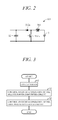
- FIG. 2 is a diagram showing configuration of a boosting circuit formed by part of the electrical circuit of FIG. 1 ;
- FIG. 3 a flowchart showing an example of processing performed by the control unit of FIG. 1 .
- An engine generator according to the embodiment of the present invention is a portable or mobile generator of weight and size a user can carry by hand.
- FIG. 1 is an electrical circuit diagram showing an overall configuration of the engine generator 100 according to the embodiment of the present invention.
- the engine generator 100 includes a general purpose engine 1 , a generator unit 2 driven by the engine 1 , and an inverter unit 3 electrically connected to the generator unit 2 .
- the engine 1 is, for example, a spark ignition, air cooled, gasoline fueled engine with a piston that reciprocates inside a cylinder and a crankshaft (output shaft) that rotates synchronously with the piston. Motive power of the engine 1 is output through the crankshaft to the generator unit 2 .
- the generator unit (generator main unit) 2 is a multipolar alternator driven by the engine 1 to generate AC power. It includes a rotor connected to and rotated integrally with the crankshaft and a stator arranged concentric with the rotor to face a peripheral surface thereof. The rotor is provided with permanent magnets. The stator is provided with UVW windings arranged at phase angle differences of 120 degree. As described below, the generator unit 2 can be driven as a starter motor by power from a battery 5 , in which case the engine 1 can be started without using the recoil starter.
- the inverter unit 3 electrically connected to the generator unit 2 includes a first power converter circuit 31 for rectifying three-phase AC current output by the generator unit 2 , a capacitor 32 electrically connected to the first power converter circuit 31 for smoothing DC current rectified by the first power converter circuit 31 , a second power converter circuit 33 electrically connected to the capacitor 32 for converting DC current smoothed by the capacitor 32 to AC current, a smoothing circuit 34 electrically connected to the second power converter circuit 33 for smoothing AC current converted by the second power converter circuit 33 , a control unit 50 for controlling switching operation of switching elements included in the first power converter circuit 31 and the second power converter circuit 33 .
- the first power converter circuit 31 is configured as an H-bridge circuit and includes three pairs of (a total of six) semiconductor switching elements 311 connected to respective U-phase, V-phase and W-phase windings of the generator unit 2 .
- the switching elements 311 are, for example, configured as MOSFET, IGBT or other transistors, and diodes (e.g., parasitic diodes) 322 are connected in parallel with the switching elements 311 .
- a gate of the switching element 311 is driven by a control signal output from the control unit 50 , and ON-OFF switching of the switching elements 311 is controlled by the control unit 50 .
- the switching elements 311 are turned OFF, so that that three-phase AC is rectified by the diodes 312 .
- the rectified current is smoothed by a capacitor 32 and sent to the inverter 32 .
- the first power converter circuit 31 ON-OFF controls the switching elements 311 to convert DC supplied from the battery 5 to three-phase AC for output to the generator unit 2 .
- the second power converter circuit 33 is connected the capacitor 32 via a positive terminal 361 and a negative terminal 362 .
- the second power converter circuit 33 has two pairs of (a total of four) semiconductor switching elements 331 configured as an H-bridge circuit.
- the switching elements 331 are constituted using transistors such as MOSFETs or IGBTs, for example, and a diode (e.g., parasitic diode) 322 is connected in parallel with each switching element 331 .
- a gate of the switching element 331 is driven by a control signal output from the control unit 50 , ON-OFF switching of the switching elements 331 is controlled by the control unit 50 , and DC current is converted to a single phase AC.
- the second power converter circuit 33 is connected with smoothing circuit 34 via a pair of output terminal 363 and 364 .
- the switching elements 331 include a first switching element 331 a located between the positive terminal 361 of the capacitor 32 and the output terminal 363 of the second power converter circuit 33 , a second switching element 331 b located between the negative terminal 362 of the capacitor 32 and the output terminal 363 of the second power converter circuit 33 , a third switching element 331 c located between the positive terminal 361 of the capacitor 32 and the output terminal 364 of the second power converter circuit 33 , and a fourth switching element 331 d located between the negative terminal 362 of the capacitor 32 and the output terminal 364 of the second power converter circuit 33 .
- the diodes 332 include a first diode 332 a whose anode is connected to the output terminal 363 of the second power converter circuit 33 and cathode is connected to the positive terminal 361 of the capacitor 32 , a second diode 332 b whose anode is connected to the negative terminal 362 of the capacitor 32 and cathode is connected to the output terminal 363 of the second power converter circuit 33 , a third diode 332 c whose anode is connected to the output terminal 364 of the second power converter circuit 33 and cathode is connected to the positive terminal 361 of the capacitor 32 , a fourth diode 332 d whose anode is connected to the negative terminal 362 of the capacitor 32 and cathode is connected to the output terminal 364 of the second power converter circuit 33 .
- the smoothing circuit (filter circuit) 34 includes a pair of coils (reactors) 341 and 342 and a capacitor.
- the smoothing circuit 34 smooths single-phase AC current received from the capacitor 32 to sine wave and outputs it through a pair of power lines 371 and 372 to an electrical load 35 .
- the power lines 371 and 372 are electrically connected through a power supply circuit 40 to the battery 5 .
- the battery 5 has a specified capacity (e.g., 12V).
- the power supply circuit 40 is arranged so as to connect the battery 5 through a connector 6 to positive and negative output terminals 365 and 366 of the smoothing circuit 34 on the power lines 371 and 372 . More exactly, a positive pole (terminal) of the battery 5 is connected through a fuse 41 , contactor 42 and diode 43 to the positive output terminal 365 , and a negative pole of the battery 5 is connected to the negative output terminal 366 .
- the contactor 42 includes a switching unit for electrically connecting (ON) and disconnecting (OFF) the battery 5 to and from the inverter unit 3 , and its ON-OFF operation is controlled by a contactor drive circuit 44 .
- a battery switch 45 is connected between the fuse 41 and the contactor 42 , and power is supplied to the control unit 50 by turning the battery switch 45 ON. This causes the contactor drive circuit 44 to turn the contactor 42 ON.
- the contactor drive circuit 44 turns the contactor 42 OFF. In other words, the contactor 42 is turned ON and OFF conjointly with ON-OFF operation of the battery switch 45 .
- the user turns the battery switch 45 ON. This turns the contactor 42 ON, and power of the battery 5 is supplied to the generator unit 2 through the smoothing circuit 34 the second power converter circuit 33 the capacitor 32 and the first power converter circuit 31 of the inverter unit 3 .
- the control unit 50 determines whether the battery switch 45 is ON, and when it determines the battery switch 45 to be ON, it ON-OFF controls the switching elements 311 of the first power converter circuit 31 to convert DC power to AC power.
- the resulting AC power is supplied to the generator unit 2 , so that a revolving magnetic field is produced in a stator winding and a rotor of the generator unit 2 rotates.
- a crankshaft 11 is rotated and the engine 1 can be started by cranking.
- a communication line is connected to the connector 6 , and internal temperature, charge state and other battery 5 data are transmitted through this communication line to the control unit 50 .
- the existing inverter circuit (inverter unit 3 ) is configured to do double duty as a boosting circuit that is in turn configured to boost voltage of the battery 5 to a predetermined voltage.
- FIG. 2 is a diagram showing configuration of a boosting circuit 101 formed by part of the electrical circuit of FIG. 1 .
- the boosting circuit 101 includes the battery 5 , the coil 341 of the smoothing circuit 34 , the second switching element 331 b and first diode 332 a of the second power converter circuit 33 , and the capacitor 32 .
- FIG. 3 is a flowchart showing an example of processing performed by the control unit 50 , particularly an example of processing at the time of starting the engine-generator 100 .
- the processing indicated by this program is started, for example, when the battery switch 45 is turned ON and power supplied to the control unit 50 in an inactive state of the engine-generator 100 and an unconnected state of the electrical load 35 , and repeated at predetermined intervals until starting of the engine 1 is completed.
- a control signal is output to the contactor drive circuit 44 to turn the contactor 42 ON. This supplies power of the battery 5 through the power supply circuit 40 to the inverter unit 3 .
- control signal is output to the switching elements 331 of the second power converter circuit 33 so as to control their switching operation.
- the first switching element 331 a , third switching element 331 c and fourth switching element 331 d of the second power converter circuit 33 are turned OFF, and the second switching element 331 b thereof is turned ON and OFF periodically at predetermined intervals.
- control signals are output to the switching elements 331 of the first power converter circuit 31 to switch the switching elements 331 ON and OFF.
- the rotor can be rotationally driven.
- the crankshaft can therefore be rotated to crank and start the engine 1 .
- the present embodiment can achieve advantages and effects such as the following.
- the engine-generator 100 includes: the engine 1 ; the generator unit 2 driven by the engine 1 ; the first power converter circuit 31 that is electrically connected to the generator unit 2 and rectifies power generated by the generator unit 2 to DC current; the capacitor 32 that is electrically connected to the first power converter circuit 31 and smooths DC current rectified by the first power converter circuit 31 ; the second power converter circuit 33 that is electrically connected to the capacitor 32 , converts DC current smoothed by the capacitor 32 to AC current and has the multiple switching elements 331 and the multiple diodes 332 connected one in parallel with each multiple switching element 331 ; and the smoothing circuit 34 that is electrically connected to the second power converter circuit 33 , smooths AC current converted by the second power converter circuit 33 , supplies the smoothed power to the electrical load 35 and has the coil 341 ( FIG.
- the engine-generator 100 further includes the battery 5 connectable to the smoothing circuit 34 , and the control unit 50 that at starting of the engine 1 controls operation of the switching elements 331 of the second power converter circuit 33 so as to form the boosting circuit 101 by the battery 5 , the coil 341 of the smoothing circuit 34 , the switching element 331 (second switching element 331 b ) and the diode 332 (first diode 332 a ) of the second power converter circuit 33 , and the capacitor 32 ( FIGS. 1 and 2 ).
- the boosting circuit 101 can be formed by putting an existing inverter circuit to double duty. As separate provision of a DC/DC converter or the like is therefore unnecessary, the boosting circuit 101 can be configured with minimal increase in number of parts, weight and cost. In other words, power of the battery 5 can be boosted and supplied to the generator unit 2 with a simple configuration. Moreover, since a configuration is adopted that boosts voltage of the battery 5 with the booster circuit 101 , the generator unit 2 (engine 1 ) can be easily started without using a high-voltage battery.
- the output terminals 363 and 364 of the second power converter circuit 33 can be connected through the smoothing circuit 34 to the positive terminal and negative terminal, respectively, of the battery 5 ( FIG. 1 ).
- the second power converter circuit 33 includes the first switching element 331 a located between the positive terminal 361 of the capacitor 32 and the output terminal 363 , the second switching element 331 b located between the negative terminal 362 of the capacitor 32 and the output terminal 363 , the first diode 332 a whose anode is connected to the output terminal 363 and cathode is connected to the positive terminal 361 , and the second diode 332 b whose anode is connected to the negative terminal 362 and cathode is connected to the output terminal 363 ( FIG. 2 ).
- the control unit 50 turns the first switching element 331 a OFF and turns the second switching element 331 b ON and OFF periodically at predetermined intervals.
- the ON-OFF control of the first switching elements 331 a and 331 b of the second power converter circuit 33 in this manner facilitates configuration because it enables formation of the boosting circuit 101 without adding new components.
- the engine-generator 100 includes the contactor 42 for establishing and cutting off connection between the smoothing circuit 34 and the battery 5 ( FIG. 1 ).
- the control unit 50 additionally controls the contactor 42 (contactor drive circuit 44 ) so as to connect the smoothing circuit 34 and the battery 5 .
- power from the battery 5 is supplied to the inverter circuit and boosted only at engine starting, whereby appropriate operation of the generator unit 2 as a starter motor can be ensured.
- control unit 50 serving as control means performs processing whereby voltage of the battery 5 (DC power supply) is boosted at starting of the engine 1 by turning the first switching element 331 a located between the positive terminal 361 (first terminal) of the capacitor 32 and the output terminal 363 (first output terminal) OFF and turning the second switching element 331 b located between the negative terminal 362 (second terminal) of the capacitor and the output terminal 363 ON and OFF periodically at predetermined intervals,
- the control means is not limited to the electrical circuit configuration shown in FIG.
- the switching elements of the second power converter circuit can be of any configuration insofar as operation of the switching elements of the second power converter circuit is controlled so as to form the booster circuit from the DC power supply, the coil of the smoothing circuit, the switching element and diode of the second power converter circuit, and the capacitor.
- the second power converter circuit can be adapted to output three-phase AC current instead of single-phase AC current.
- the switching unit is not limited to this configuration.
- the present invention enables formation of a boosting circuit by putting an existing inverter circuit to double duty, without need to provide a separate a DC/DC converter or the like, and therefore minimizes increase in number of parts, weight and cost
Landscapes
- Engineering & Computer Science (AREA)
- Power Engineering (AREA)
- Control Of Eletrric Generators (AREA)
- Inverter Devices (AREA)
- Dc-Dc Converters (AREA)
Abstract
Description
Claims (2)
Applications Claiming Priority (2)
| Application Number | Priority Date | Filing Date | Title |
|---|---|---|---|
| JP2017066551A JP6832775B2 (en) | 2017-03-30 | 2017-03-30 | Engine generator |
| JP2017-066551 | 2017-03-30 |
Publications (2)
| Publication Number | Publication Date |
|---|---|
| US20180287534A1 US20180287534A1 (en) | 2018-10-04 |
| US10418924B2 true US10418924B2 (en) | 2019-09-17 |
Family
ID=63670912
Family Applications (1)
| Application Number | Title | Priority Date | Filing Date |
|---|---|---|---|
| US15/938,734 Active US10418924B2 (en) | 2017-03-30 | 2018-03-28 | Engine generator with a boosting circuit for starting an engine |
Country Status (3)
| Country | Link |
|---|---|
| US (1) | US10418924B2 (en) |
| JP (1) | JP6832775B2 (en) |
| CN (1) | CN108695963B (en) |
Citations (6)
| Publication number | Priority date | Publication date | Assignee | Title |
|---|---|---|---|---|
| EP0488108A1 (en) * | 1990-11-30 | 1992-06-03 | Shinko Electric Co. Ltd. | Engine-operated generator system |
| JPH0622461A (en) * | 1992-01-28 | 1994-01-28 | Shinko Electric Co Ltd | Engine type power generator with built-in battery |
| US20110121769A1 (en) * | 2009-11-20 | 2011-05-26 | Hamilton Sundstrand Corporation | Multi-tasking power processor for a vehicle electric system |
| US20120291739A1 (en) * | 2011-05-17 | 2012-11-22 | Honda Motor Co., Ltd. | Start control apparatus for engine generator |
| JP5839835B2 (en) | 2011-05-17 | 2016-01-06 | 本田技研工業株式会社 | Parallel operation controller for inverter generator |
| US20170288575A1 (en) * | 2016-04-01 | 2017-10-05 | Murata Manufacturing Co., Ltd. | Power converter |
Family Cites Families (6)
| Publication number | Priority date | Publication date | Assignee | Title |
|---|---|---|---|---|
| JPS6022461A (en) * | 1983-07-16 | 1985-02-04 | Takashi Nosaka | Generating apparatus of gravity rotary engine |
| JPH05176552A (en) * | 1991-12-24 | 1993-07-13 | Shinko Electric Co Ltd | Engine type power generator with built-in battery |
| JP4203471B2 (en) * | 2004-12-28 | 2009-01-07 | 東京瓦斯株式会社 | Hot water system |
| CN101702532B (en) * | 2009-11-26 | 2012-05-23 | 芜湖国睿兆伏电子股份有限公司 | Charging controller of wind driven generator and control method thereof |
| CN102710006B (en) * | 2012-05-18 | 2014-12-24 | 深圳市健网科技有限公司 | Double-power supply system with balance bridge arm |
| WO2014033868A1 (en) * | 2012-08-30 | 2014-03-06 | 三洋電機株式会社 | Input circuit and power conversion apparatus |
-
2017
- 2017-03-30 JP JP2017066551A patent/JP6832775B2/en not_active Expired - Fee Related
-
2018
- 2018-03-22 CN CN201810241011.7A patent/CN108695963B/en not_active Expired - Fee Related
- 2018-03-28 US US15/938,734 patent/US10418924B2/en active Active
Patent Citations (8)
| Publication number | Priority date | Publication date | Assignee | Title |
|---|---|---|---|---|
| EP0488108A1 (en) * | 1990-11-30 | 1992-06-03 | Shinko Electric Co. Ltd. | Engine-operated generator system |
| JPH04203471A (en) * | 1990-11-30 | 1992-07-24 | Shinko Electric Co Ltd | Engine type power generating device |
| US5237260A (en) * | 1990-11-30 | 1993-08-17 | Shinko Electric Co., Ltd. | Engine-operated generator system |
| JPH0622461A (en) * | 1992-01-28 | 1994-01-28 | Shinko Electric Co Ltd | Engine type power generator with built-in battery |
| US20110121769A1 (en) * | 2009-11-20 | 2011-05-26 | Hamilton Sundstrand Corporation | Multi-tasking power processor for a vehicle electric system |
| US20120291739A1 (en) * | 2011-05-17 | 2012-11-22 | Honda Motor Co., Ltd. | Start control apparatus for engine generator |
| JP5839835B2 (en) | 2011-05-17 | 2016-01-06 | 本田技研工業株式会社 | Parallel operation controller for inverter generator |
| US20170288575A1 (en) * | 2016-04-01 | 2017-10-05 | Murata Manufacturing Co., Ltd. | Power converter |
Non-Patent Citations (1)
| Title |
|---|
| A machine translation of Yoshida (JP06-022461); 10 pages, translated Jan. 4, 2019. * |
Also Published As
| Publication number | Publication date |
|---|---|
| US20180287534A1 (en) | 2018-10-04 |
| JP2018168751A (en) | 2018-11-01 |
| CN108695963A (en) | 2018-10-23 |
| CN108695963B (en) | 2022-12-23 |
| JP6832775B2 (en) | 2021-02-24 |
Similar Documents
| Publication | Publication Date | Title |
|---|---|---|
| CN100366892C (en) | engine generator | |
| CN102790586B (en) | Inverter generator | |
| US10724489B2 (en) | Engine-generator starting apparatus | |
| US20130113283A1 (en) | Charging and distribution control | |
| US10483890B2 (en) | Engine generator comprising an electrical load-dependent delta to WYE switching unit | |
| US20110037442A1 (en) | Permanent magnet generator control | |
| US10697416B2 (en) | Engine generator | |
| US10763675B2 (en) | Power generator system | |
| US20170207738A1 (en) | Electric machine for the power supply of a motor vehicle electrical system | |
| US11316457B2 (en) | Inverter type engine generator | |
| EP2719888A1 (en) | Dual-DC bus starter/generator | |
| JP4478185B2 (en) | Engine starter for vehicle | |
| US10418924B2 (en) | Engine generator with a boosting circuit for starting an engine | |
| JP5690651B2 (en) | Inverter generator | |
| US11121653B2 (en) | Inverter generator | |
| KR101934719B1 (en) | On Board Charger for Controlling Output Voltage and Charging Method Threrof | |
| US11476787B2 (en) | Inverter type engine generator | |
| JP5052255B2 (en) | AC rotating machine | |
| US9712100B2 (en) | Electric rotating machine and control method therefor | |
| US20240317090A1 (en) | Charging system for electric vehicle | |
| GB2494715A (en) | Power control circuit for self-excited electrical generator | |
| JP2012244690A (en) | Inverter generator | |
| JP6492450B2 (en) | Rotating electric machine | |
| CN117394612A (en) | Low-cost double-voltage power supply generator system | |
| US20210028643A1 (en) | Hybrid-type engine generator controller |
Legal Events
| Date | Code | Title | Description |
|---|---|---|---|
| AS | Assignment |
Owner name: HONDA MOTOR CO., LTD., JAPAN Free format text: ASSIGNMENT OF ASSIGNORS INTEREST;ASSIGNORS:MAEDAKO, MINORU;MATSUHISA, TETSUYA;SHIBATA, KENJI;AND OTHERS;REEL/FRAME:045378/0539 Effective date: 20180309 |
|
| FEPP | Fee payment procedure |
Free format text: ENTITY STATUS SET TO UNDISCOUNTED (ORIGINAL EVENT CODE: BIG.); ENTITY STATUS OF PATENT OWNER: LARGE ENTITY |
|
| STPP | Information on status: patent application and granting procedure in general |
Free format text: DOCKETED NEW CASE - READY FOR EXAMINATION |
|
| STPP | Information on status: patent application and granting procedure in general |
Free format text: NON FINAL ACTION MAILED |
|
| STPP | Information on status: patent application and granting procedure in general |
Free format text: NOTICE OF ALLOWANCE MAILED -- APPLICATION RECEIVED IN OFFICE OF PUBLICATIONS |
|
| STPP | Information on status: patent application and granting procedure in general |
Free format text: PUBLICATIONS -- ISSUE FEE PAYMENT VERIFIED |
|
| STCF | Information on status: patent grant |
Free format text: PATENTED CASE |
|
| MAFP | Maintenance fee payment |
Free format text: PAYMENT OF MAINTENANCE FEE, 4TH YEAR, LARGE ENTITY (ORIGINAL EVENT CODE: M1551); ENTITY STATUS OF PATENT OWNER: LARGE ENTITY Year of fee payment: 4 |