US10411302B2 - Lithium secondary battery - Google Patents
Lithium secondary battery Download PDFInfo
- Publication number
- US10411302B2 US10411302B2 US15/293,475 US201615293475A US10411302B2 US 10411302 B2 US10411302 B2 US 10411302B2 US 201615293475 A US201615293475 A US 201615293475A US 10411302 B2 US10411302 B2 US 10411302B2
- Authority
- US
- United States
- Prior art keywords
- silicon
- graphene
- secondary battery
- lithium secondary
- composite
- Prior art date
- Legal status (The legal status is an assumption and is not a legal conclusion. Google has not performed a legal analysis and makes no representation as to the accuracy of the status listed.)
- Active, expires
Links
Images


Classifications
-
- H—ELECTRICITY
- H01—ELECTRIC ELEMENTS
- H01M—PROCESSES OR MEANS, e.g. BATTERIES, FOR THE DIRECT CONVERSION OF CHEMICAL ENERGY INTO ELECTRICAL ENERGY
- H01M10/00—Secondary cells; Manufacture thereof
- H01M10/05—Accumulators with non-aqueous electrolyte
- H01M10/056—Accumulators with non-aqueous electrolyte characterised by the materials used as electrolytes, e.g. mixed inorganic/organic electrolytes
- H01M10/0564—Accumulators with non-aqueous electrolyte characterised by the materials used as electrolytes, e.g. mixed inorganic/organic electrolytes the electrolyte being constituted of organic materials only
- H01M10/0566—Liquid materials
- H01M10/0569—Liquid materials characterised by the solvents
-
- H—ELECTRICITY
- H01—ELECTRIC ELEMENTS
- H01M—PROCESSES OR MEANS, e.g. BATTERIES, FOR THE DIRECT CONVERSION OF CHEMICAL ENERGY INTO ELECTRICAL ENERGY
- H01M10/00—Secondary cells; Manufacture thereof
- H01M10/05—Accumulators with non-aqueous electrolyte
- H01M10/052—Li-accumulators
-
- H—ELECTRICITY
- H01—ELECTRIC ELEMENTS
- H01M—PROCESSES OR MEANS, e.g. BATTERIES, FOR THE DIRECT CONVERSION OF CHEMICAL ENERGY INTO ELECTRICAL ENERGY
- H01M10/00—Secondary cells; Manufacture thereof
- H01M10/05—Accumulators with non-aqueous electrolyte
- H01M10/056—Accumulators with non-aqueous electrolyte characterised by the materials used as electrolytes, e.g. mixed inorganic/organic electrolytes
- H01M10/0564—Accumulators with non-aqueous electrolyte characterised by the materials used as electrolytes, e.g. mixed inorganic/organic electrolytes the electrolyte being constituted of organic materials only
- H01M10/0566—Liquid materials
- H01M10/0568—Liquid materials characterised by the solutes
-
- H—ELECTRICITY
- H01—ELECTRIC ELEMENTS
- H01M—PROCESSES OR MEANS, e.g. BATTERIES, FOR THE DIRECT CONVERSION OF CHEMICAL ENERGY INTO ELECTRICAL ENERGY
- H01M4/00—Electrodes
- H01M4/02—Electrodes composed of, or comprising, active material
- H01M4/36—Selection of substances as active materials, active masses, active liquids
- H01M4/38—Selection of substances as active materials, active masses, active liquids of elements or alloys
- H01M4/386—Silicon or alloys based on silicon
-
- H—ELECTRICITY
- H01—ELECTRIC ELEMENTS
- H01M—PROCESSES OR MEANS, e.g. BATTERIES, FOR THE DIRECT CONVERSION OF CHEMICAL ENERGY INTO ELECTRICAL ENERGY
- H01M4/00—Electrodes
- H01M4/02—Electrodes composed of, or comprising, active material
- H01M4/36—Selection of substances as active materials, active masses, active liquids
- H01M4/48—Selection of substances as active materials, active masses, active liquids of inorganic oxides or hydroxides
- H01M4/485—Selection of substances as active materials, active masses, active liquids of inorganic oxides or hydroxides of mixed oxides or hydroxides for inserting or intercalating light metals, e.g. LiTi2O4 or LiTi2OxFy
-
- H—ELECTRICITY
- H01—ELECTRIC ELEMENTS
- H01M—PROCESSES OR MEANS, e.g. BATTERIES, FOR THE DIRECT CONVERSION OF CHEMICAL ENERGY INTO ELECTRICAL ENERGY
- H01M4/00—Electrodes
- H01M4/02—Electrodes composed of, or comprising, active material
- H01M4/36—Selection of substances as active materials, active masses, active liquids
- H01M4/362—Composites
- H01M4/366—Composites as layered products
-
- Y—GENERAL TAGGING OF NEW TECHNOLOGICAL DEVELOPMENTS; GENERAL TAGGING OF CROSS-SECTIONAL TECHNOLOGIES SPANNING OVER SEVERAL SECTIONS OF THE IPC; TECHNICAL SUBJECTS COVERED BY FORMER USPC CROSS-REFERENCE ART COLLECTIONS [XRACs] AND DIGESTS
- Y02—TECHNOLOGIES OR APPLICATIONS FOR MITIGATION OR ADAPTATION AGAINST CLIMATE CHANGE
- Y02E—REDUCTION OF GREENHOUSE GAS [GHG] EMISSIONS, RELATED TO ENERGY GENERATION, TRANSMISSION OR DISTRIBUTION
- Y02E60/00—Enabling technologies; Technologies with a potential or indirect contribution to GHG emissions mitigation
- Y02E60/10—Energy storage using batteries
-
- Y—GENERAL TAGGING OF NEW TECHNOLOGICAL DEVELOPMENTS; GENERAL TAGGING OF CROSS-SECTIONAL TECHNOLOGIES SPANNING OVER SEVERAL SECTIONS OF THE IPC; TECHNICAL SUBJECTS COVERED BY FORMER USPC CROSS-REFERENCE ART COLLECTIONS [XRACs] AND DIGESTS
- Y02—TECHNOLOGIES OR APPLICATIONS FOR MITIGATION OR ADAPTATION AGAINST CLIMATE CHANGE
- Y02T—CLIMATE CHANGE MITIGATION TECHNOLOGIES RELATED TO TRANSPORTATION
- Y02T10/00—Road transport of goods or passengers
- Y02T10/60—Other road transportation technologies with climate change mitigation effect
- Y02T10/70—Energy storage systems for electromobility, e.g. batteries
-
- Y02T10/7011—
Definitions
- the present disclosure relates to a lithium secondary battery.
- Silicon has been studied for use as a negative electrode material for lithium ion batteries since silicon has a high theoretical capacity of 4200 milliampere-hours per gram (mAh/g) and a low cost.
- silicon undergoes a volume expansion when alloyed with lithium during discharge of a battery to form Li 4.4 Si and thus the silicon active material becomes electrically isolated in the electrode and the electrolyte decomposition reaction increases according to the increase in the specific surface area of the silicon.
- a structure that reduces the volume expansion of the silicon so that it undergoes less pulverization has been developed or alternatively formation of a coating layer of carbon or the like on a surface of the silicon has been suggested.
- general silicon materials do not exhibit satisfactory volume expansion reduction effects or battery charging/discharging efficiency. There remains a need for improved lithium secondary battery materials.
- a lithium secondary battery with enhanced capacity retention and improved charging/discharging efficiency.
- a lithium secondary battery includes: a negative electrode, a positive electrode, and an electrolyte disposed between the negative electrode and the positive electrode, wherein the negative electrode includes a silicon composite including silicon, a silicon oxide of the formula SiO x wherein 0 ⁇ x ⁇ 2 and disposed on the silicon, and a graphene disposed on the silicon oxide, or a carbonaceous composite including the silicon composite and a carbonaceous material, which is different from the graphene, and wherein at least one of the negative electrode and the electrolyte includes an ionic liquid containing a fluorosulfonyl imide anion and a lithium salt.
- FIG. 1A is a schematic view illustrating a process in which a composite according to an exemplary embodiment forms a stable solid electrolyte interface (SEI) film;
- SEI solid electrolyte interface
- FIG. 1B is a schematic view illustrating a method of implementing a clamping effect as a graphene layer helps silicon particles to expand and lithium ions to diffuse during a lithiation process;
- FIG. 1C is a schematic view illustrating an exemplary embodiment in which graphene in the form of a nanosheet is disposed on silicon wires with a silicon oxide thereon;
- FIG. 1D is a schematic view illustrating an exemplary embodiment in which graphene in the form of a film is disposed on silicon wires with a silicon oxide thereon;
- FIG. 1E is a schematic view illustrating a method of implementing a clamping effect as a graphene layer helps silicon particles having no defect to expand and lithium ions to diffuse during a lithiation process;
- FIG. 2 is a schematic view of a lithium battery according to an exemplary embodiment
- FIG. 3 is a graph of capacity versus cycle number, showing changes in capacity retention of coin cells manufactured according to Example 1 and Comparative Examples 1 and 6 to 9;
- FIG. 4 is a graph of coulombic efficiency (%) versus charge/discharge cycle number, showing changes in Coulombic efficiency of coin cells manufactured according to Example 1 and Comparative Examples 5, 8 and 9;
- FIG. 5 is a graph of 1 st cycle differential capacity (dQ/dV) versus voltage of the coin cells of Example 1 and Comparative Examples 1 and 6 to 9;
- FIG. 6 is a graph of 2 nd cycle differential capacity (dQ/dV) versus voltage of the lithium secondary batteries of Example 1 and Comparative Example 1;
- FIGS. 7A to 7C are graphs of intensity (arbitrary units, a.u.) versus binding energy (eV) determined by X-ray photoelectron spectroscopy (XPS) for the lithium secondary batteries of Example 1 and Comparative Example 1;
- FIG. 8A is a graph showing voltage versus capacity for the 2 nd and 100 th cycles of the coin cell of Example 1;
- FIG. 8B is a graph showing voltage versus capacity for the 2 nd and 100 th cycles of the coin cell of Comparative Example 1;
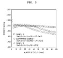
- FIG. 9 is a graph of capacity versus cycle number, showing changes in capacity retention of coin cells manufactured according to Examples 1 and 2 and the coin cell of Comparative Example 1;
- FIG. 10 is a graph showing Coulombic efficiency a versus cycle number for coin cells manufactured according to Examples 1 to 4 and Comparative Examples 1 to 4;
- FIG. 11 is a graph showing capacity versus cycle number for coin cells manufactured according to Examples 1, 5, 6 and 8 and the coin cell of Comparative Example 2;
- FIG. 12 is a graph showing charging/discharging efficiency versus cycle number for the coin cells of Examples 1, 5, 6 and 8 and Comparative Example 2;
- FIG. 13 is a graph showing capacity versus cycle number for the coin cells of Example 1 and Comparative Examples 1 to 3;
- FIG. 14 is a graph showing coulombic efficiency (%) versus cycle number for the coin cells of Example 1 and Comparative Examples 1 to 3;
- FIG. 15 is a graph showing amount of residual electrolyte (weight percent, “wt %”) versus number of bending cycles for coin cells manufactured according to Examples 18 and 19 and Comparative Examples 11 and 12;
- FIGS. 16A to 16H are images showing bending test results for the coin cells of Example 18 and Comparative Example 11, respectively;
- FIGS. 17A and 17C are transmission electron microscope (TEM) images of a composite prepared according to Preparation Example 1;
- FIGS. 17B and 17D are TEM images of a composite prepared according to Preparation Example 3.
- FIG. 18 is a graph showing Raman spectra (intensity (a.u.) versus Raman shift (centimeter ⁇ 1 “cm ⁇ 1 ”) for the composite of Preparation Example 3 and silicon nanoparticles with an amorphous carbon film formed thereon, prepared according to Comparative Preparation Example 2; and
- FIG. 19 is a graph showing an infrared (IR) spectrum (absorbance (arbitrary units “a.u.”) versus wave number (centimeter ⁇ 1 “cm ⁇ 1 ”)) for an electrolyte used in Example 2.
- IR infrared
- first,” “second,” “third,” etc. may be used herein to describe various elements, components, regions, layers, and/or sections, these elements, components, regions, layers, and/or sections should not be limited by these terms. These terms are only used to distinguish one element, component, region, layer or section from another element, component, region, layer, or section. Thus, “a first element,” “component,” “region,” “layer,” or “section” discussed below could be termed a second element, component, region, layer, or section without departing from the teachings herein.
- relative terms such as “lower” or “bottom” and “upper” or “top,” may be used herein to describe one element's relationship to another element as illustrated in the Figures. It will be understood that relative terms are intended to encompass different orientations of the device in addition to the orientation depicted in the Figures. For example, if the device in one of the figures is turned over, elements described as being on the “lower” side of other elements would then be oriented on “upper” sides of the other elements. The exemplary term “lower,” can therefore, encompasses both an orientation of “lower” and “upper,” depending on the particular orientation of the figure.
- “About” or “approximately” as used herein is inclusive of the stated value and means within an acceptable range of deviation for the particular value as determined by one of ordinary skill in the art, considering the measurement in question and the error associated with measurement of the particular quantity (e.g., the limitations of the measurement system). For example, “about” can mean within one or more standard deviations, or within ⁇ 30%, 20%, 10%, or 5% of the stated value.
- Exemplary embodiments are described herein with reference to cross section illustrations that are schematic illustrations of idealized embodiments. As such, variations from the shapes of the illustrations as a result, for example, of manufacturing techniques and/or tolerances, are to be expected. Thus, embodiments described herein should not be construed as limited to the particular shapes of regions as illustrated herein but are to include deviations in shapes that result, for example, from manufacturing. For example, a region illustrated or described as flat may have rough and/or nonlinear features. Moreover, sharp angles that are illustrated may be rounded. Thus, the regions illustrated in the figures are schematic in nature and their shapes are not intended to illustrate the precise shape of a region and are not intended to limit the scope of the present claims.
- a lithium secondary battery includes a negative electrode, a positive electrode, and an electrolyte disposed between the negative electrode and the positive electrode, wherein the negative electrode includes i) a silicon composite including silicon (Si), a silicon oxide of the formula SiO x wherein 0 ⁇ x ⁇ 2 disposed on the silicon, and a graphene disposed on the silicon oxide or ii) a carbonaceous composite including the silicon composite and a carbonaceous material, which is different from the graphene, and wherein at least one of the negative electrode and the electrolyte includes i) an ionic liquid containing a fluorosulfonyl imide anion and ii) a lithium salt.
- the negative electrode includes i) a silicon composite including silicon (Si), a silicon oxide of the formula SiO x wherein 0 ⁇ x ⁇ 2 disposed on the silicon, and a graphene disposed on the silicon oxide or ii) a carbonaceous composite including the silicon composite and a carbonaceous material, which is different from
- the electrolyte includes an ionic liquid containing a fluorosulfonyl imide anion and a lithium salt.
- the fluorosulfonyl imide anion may be, for example, (FSO 2 ) 2 N ⁇ , (CF 3 SO 2 ) 2 N ⁇ , (C 2 F 5 SO 2 ) 2 N ⁇ , (C 2 F 5 SO 2 )(CF 3 SO 2 )N ⁇ , or (FSO 2 )(CF 3 SO 2 )N ⁇ .
- a silicon material is pulverized due to the volume expansion occurring during battery charging and discharging, or an interface between new electrolyte and a silicon active material is continuously formed, which causes a side reaction therebetween.
- a lithium secondary battery employing a negative electrode including such silicon material has reduced charging/discharging efficiency and deteriorated lifespan characteristics.
- a composite in which a graphene is grown on a silicon oxide on silicon.
- the composite may form an unstable solid electrolyte interface (SEI) film due to decomposition of the electrolyte at the basal-plane site and edge-plane site of graphene.
- SEI solid electrolyte interface
- silicon pulverization or formation of irreversible c-Li x Si due to overcharging may occur.
- an interface is continuously formed between the new electrolyte and the active material, which causes a side reaction therebetween.
- a lithium secondary battery employing a negative electrode including such a composite exhibits reduced durability and deteriorated charging/discharging efficiency due to the decrease in capacity.
- the present inventors provide a lithium secondary battery in which, as illustrated in FIG. 1A , an electrochemically stable protective film 14 is disposed on a surface of graphene 13 of a composite 10 by using an electrolyte 15 including an ionic liquid containing a fluorosulfonyl imide anion. Accordingly, the side reaction between a surface of silicon of the composite 10 and the electrolyte 15 is effectively suppressed. In such a lithium secondary battery, formation of crystalline Li x Si is suppressed due to the prevention of overcharging by the stable protective film 14 , thus increasing capacity durability of the lithium secondary battery.
- the lithium salt may be any suitable lithium salt including those used in the art.
- the lithium salt may be LiSCN, LiN(CN) 2 , LiClO 4 , LiBF 4 , LiAsF 6 , LiPF 6 , LiCF 3 SO 3 , Li(CF 3 SO 2 ) 2 N (“LiTFSI”), LiSbF 6 , Li(CF 3 SO 2 ) 3 C, LiPF 3 (CF 2 CF 3 ) 3 , LiPF 3 (CF 3 ) 3 , LiB(C 2 O 4 ) 2 , Li(FSO 2 ) 2 N (“LiFSI”), LiN(SO 2 C 2 F 5 )(CF 3 SO 2 ), LiN(SO 2 C 2 F 5 ) 2 , LiPF 3 (CF 2 CF 3 ) 3 , LiCl, LiI, or a mixture thereof.
- the lithium salt may be, for example, a lithium salt including a fluorosulfonyl imide anion, such as LiTFSI or LiFS
- the composite 10 has a structure including silicon (Si) 11 , a silicon oxide 12 of the formula SiO x where 0 ⁇ x ⁇ 2 disposed on the silicon 11 , and a graphene 13 disposed on the silicon oxide 12 .
- the graphene 13 has a structure that is directly grown on the silicon oxide 12 .
- the graphene 13 may be in the form of a film or a nanosheet. Referring to FIG. 1A , the graphene 13 has a film type.
- the composite 10 has a protective film for preventing a reaction between a surface of silicon and the electrolyte such that the graphene film can slide according to the volumetric change of silicon during charging and discharging of the lithium battery. Accordingly, the surface of the silicon is protected.
- a graphene with a high conductivity and pliable to volume expansion is directly grown on the surface of silicon and accordingly, volume expansion is suppressed and pulverization of the silicon may be reduced.
- the opportunity of direct contact between the silicon and the electrolyte may be reduced by the graphene, thus reducing the formation of an SEI layer.
- XPS X-ray photoelectron spectrometry
- electrolyte molecules are considered to more easily contact a surface of a negative electrode by passing through the protective film, as compared to the case in which an electrolyte including an ionic liquid containing a fluorosulfonyl imide anion is used.
- the ionic liquid containing a fluorosulfonyl imide anion may be at least one selected from compounds having: at least one cation selected from ammonium cations, pyrrolidinium cations, pyridinium cations, pyrimidinium cations, imidazolium cations, piperidinium cations, pyrazolium cations, oxazolium cations, pyridazinium cations, phosphonium cations, sulfonium cations, and triazolium cations; and at least one anion selected from (FSO 2 ) 2 N ⁇ , (CF 3 SO 2 ) 2 N ⁇ , (C 2 F 5 SO 2 ) 2 N ⁇ , (C 2 F 5 SO 2 )(CF 3 SO 2 )N ⁇ , and (FSO 2 )(CF 3 SO 2 )N ⁇ .
- the ionic liquid containing a fluorosulfonyl imide anion may be, for example, N-methyl-N-propylpyrrolidinium bis(fluorosulfonyl)imide, N-methyl-N-propylpyrrolidinium bis(trifluoromethanesulfonyl)imide, N-butyl-N-methylpyrrolidinium bis(3-trifluoromethylsulfonyl)imide, N-butyl-N-methylpyrrolidinium bis(fluorosulfonyl)imide, 1-butyl-3-methylimidazolium bis(trifluoromethylsulfonyl)imide, 1-butyl-3-methylimidazolium bis(fluorosulfonyl)imide, 1-ethyl-3-methylimidazolium bis(trifluoromethylsulfonyl)imide and 1-ethyl-3-methylimidazolium bis(fluorosulfon
- the amount of the ionic liquid containing a fluorosulfonyl imide anion may be from about 1 part by weight to about 95 parts by weight, for example, from about 70 parts by weight to about 90 parts by weight, based on 100 parts by weight of the electrolyte.
- amount of the ionic liquid containing a fluorosulfonyl imide anion is within the above range, a lithium secondary battery with excellent charging/discharging efficiency and capacity retention may be manufactured.
- the amount of the lithium salt may be from about 0.2M to about 2M, for example, from about 0.5M to about 1.0M.
- the electrolyte has an appropriate viscosity and thus there is no risk of leakage of the electrolyte.
- a lithium secondary battery with high charging/discharging efficiency and capacity retention may be manufactured.
- 2D peaks obtained by Raman analysis appear at about 2600 to about 2750 cm ⁇ 1 .
- the Raman analysis results are obtained by measurement with light having a wavelength of 514 nm.
- An intensity ratio of D and G (D/G) obtained by Raman analysis may be from about 1.0 to about 4.0, for example, 2.0, and an intensity ratio of G and 2D (G/2D) of graphene obtained by Raman analysis may be from about 1.0 to about 6.0, for example, 2.0.
- the graphene has a high crystallinity when having the Raman analysis characteristics described above.
- the electrolyte has a viscosity of about 50 cp to about 300 cp, for example, about 150 cp to 223 cp.
- the viscosity of the electrolyte is within the above range, it is easy to inject the electrolyte into a lithium secondary battery and there is no risk of leakage of the electrolyte.
- high bending durability may be achieved, which enables the manufacture of a flexible battery.
- a silicon oxide of the formula SiO x where 0 ⁇ x ⁇ 2, which is a natural oxide disposed on silicon is not removed and rather used as a seed layer material for forming graphene and as a result, graphene is disposed on the silicon.
- the shape, structure, thickness and the like of graphene may be adjusted using the silicon oxide as a seed layer material according to the purpose of use.
- the silicon oxide of the formula SiO x where 0 ⁇ x ⁇ 2 is an unstable material which lacks oxygen compared to silica (SiO 2 ) and has a tendency to form a stable material by reacting with other reactive materials such as carbon source gas.
- a silicon oxide film is used as a seed layer material for forming graphene.
- the thickness of the silicon oxide (SiO x where 0 ⁇ x ⁇ 2) film disposed on silicon has a very important effect on the shape, structure and the like of the graphene.
- the thickness of the silicon oxide (SiO x where 0 ⁇ x ⁇ 2) film may be changed using a manufacturing process used in the formation of graphene, e.g., the composition of carbon source gas needed to form graphene.
- the thickness of the silicon oxide (SiO x where 0 ⁇ x ⁇ 2) film may be 300 ⁇ m or less.
- the thickness of the silicon oxide (SiO x where 0 ⁇ x ⁇ 2) film of the composite used in a battery may be 10 nanometer (nm) or less, for example, from about 0.1 to about 10 nm, for example, from about 0.1 nm to about 5 nm.
- the composite including the silicon oxide (SiO x where 0 ⁇ x ⁇ 2) film having the thickness within the above ranges is used, a lithium secondary battery with excellent capacity characteristics is obtained.
- the graphene is disposed on the silicon oxide (SiO x where 0 ⁇ x ⁇ 2) film of the silicon by gaseous carbon deposition that does not use a catalyst.
- the gaseous carbon deposition is performed by heat-treating silicon coated with a silicon oxide of the formula SiO x in an atmosphere comprising at least one gas selected from a compound represented by Formula 1 below, a compound represented by Formula 2 below, and an oxygen-containing gas represented by Formula 3 below: C n H (2n+2 ⁇ a) [OH] a Formula 1
- n is an integer of 1 to 20 and a is 0 or 1, C n H (2n) Formula 2
- n is an integer of 2 to 6
- x is an integer of 1 to 20
- y is 0 or an integer of 1 to 20
- z is 1 or 2.
- the gaseous carbon deposition described above is believed to be related to reforming of the silicon covered with the silicon oxide of the formula SiO x included in the gas mixture by using CO 2 .
- the compound of Formula 1 is methane (i.e., n is 1 and a is 0 in Formula 1)
- carbon deposition occurs on a composite oxide based on a reaction (e.g., a Boudouard reaction of Reaction Scheme 2) that occurs as a side reaction in the reforming reaction of Reaction Scheme 1.
- a reaction e.g., a Boudouard reaction of Reaction Scheme 2
- carbon deposition occurring from decomposition of the compound of Formula 1 e.g., the reaction of Reaction Scheme 3 in the case of methane, is used.
- reaction that may occur during the heat treatment process of the carbon coating method is not limited to the reaction described above, and reactions other than the foregoing reaction may occur.
- graphene is grown directly on silicon covered with a silicon oxide (SiO x ) and thus the graphene is closely adhered to the silicon.
- a SiO x layer may be first formed on the silicon by reaction with an oxygen-containing gas mixture. Then graphene may be formed thereon by reaction with a carbon gas mixture through a process of reacting the carbon gas mixture and the oxygen-containing gas mixture.
- An adherency between the silicon and the graphene may be evaluated by using a distance between a silicon of the silicon oxide (SiO x ) thereon and the graphene as determined with a scanning electron microscope.
- the distance between the graphene and the silicon of the silicon oxide (SiO x ) may be about 10 nm or less, for example, from about 0.5 nm to about 10 nm. In another embodiment, the distance between the graphene and the silicon of the silicon oxide (SiO x ) may be about 1 nm or less, for example, from about 0.5 nm to about 1 nm.
- the graphene extends from the silicon of the silicon oxide (SiO x ) by a distance of 1 nm or less, for example, from about 0.5 nm to about 1 nm and thus the adherency and uniformity therebetween are very high.
- the graphene may be oriented at an angle ranging from about 0° to about 90° with respect to a primary axis of the silicon.
- the graphene may include one to 20 layers of graphene, and the total thickness of the graphene may be about 0.6 nm to about 12 nm.
- the graphene may be oriented at an angle ranging from about 0° to about 90° with respect to a primary axis of the silicon.
- about 90% or greater, for example, from about 90% to about 100%, for example, from about 99% to about 100%, for example, from about 99.5% to about 99.99% of the graphene extends from silicon nanoparticles with the silicon oxide (SiO x ) film formed thereon by a distance of about 1 nm or less and is uniformly positioned.
- a shape of the silicon is not limited, and may be, for example, at least one selected from nanowires, nanoparticles, nanotubes, nanorods, a wafer, and nanoribbons.
- the silicon may have a shape of a nanowire.
- a cross-sectional diameter of the silicon nanowire may be less than about 500 nm, for example, from about 100 nm to about 300 nm.
- the nanowire may have a diameter of greater than about 50 nm, for example, from about 50 nm to about 100 nm.
- a silicon oxide (SiO x where 0 ⁇ x ⁇ 2) film is disposed on silicon nanowires, and graphene may be formed thereon.
- a silicon oxide (SiO x where 0 ⁇ x ⁇ 2) film may be disposed on silicon nanoparticles, and graphene may be formed thereon.
- the silicon nanoparticles may have an average diameter of from about 1 ⁇ m to 40 ⁇ m, for example, from about 40 nm to about 100 nm.
- the silicon wafer may have a thickness of about 2 mm or less, for example, from about 0.001 mm to about 2 mm.
- the graphene is a polycyclic aromatic molecule containing a plurality of carbon atoms that are covalently bonded to one another.
- the covalently bonded carbon atoms form a 6-membered ring as a basic repeating unit, but may further include a 5-membered ring and/or a 7-membered ring.
- the graphene may appear as a single layer of the covalently bonded carbon atoms (generally, having a sp 2 bond).
- the graphene may be a single layer or multiple layers of carbon stacked one upon another, e.g., about 1 layer to about 100 layers, for example, about 2 layers to about 100 layers, for example, about 3 layers to about 50 layers.
- the graphene may be in the form of a nanosheet or a layer (or a film).
- nanosheet and “layer” used herein are defined as follows.
- the term “nanosheet” denotes a structure disposed in an irregular form on the silicon oxide and the term “layer” denotes a structure that is continuously and uniformly disposed on the silicon oxide.
- FIG. 1C illustrates a composite in which a graphene nanosheet 11 is disposed on a silicon wire 10 covered with a silicon oxide.
- FIG. 1D illustrates a composite in which a graphene film 11 is disposed on a silicon wire 10 covered with a silicon oxide.
- FIGS. 1C and 1D Views on the right sides of FIGS. 1C and 1D illustrate lithiated composites used as a negative active material.
- FIG. 1B is a view illustrating the clamping effect in which, during lithiation, a graphene film helps to inflate silicon nanoparticles and to diffuse lithium ions.
- a graphene encapsulation layer serves to suppress particle crushing and pulverization which occur in general silicon particles.
- a graphene sliding layer acts as a clamping layer that prevents disintegration of silicon particles.
- an alloying reaction between lithium ions and Si proceeds and as a result, a conducting path with a very high specific capacity and being continuously formed between particles is provided.
- the graphene layer(s) acts as a clamping layer for preventing the disintegration of silicon particles.
- the amount of the graphene may be from about 0.001 parts by weight to about 90 parts by weight, for example, from about 0.01 parts by weight to about 20 parts by weight, for example, from about 0.01 parts by weight to about 10 parts by weight, based on 100 parts by weight of the composite.
- the amount of the graphene is within the above range, the graphene has a great effect on suppressing the volume of the silicon and a high conductivity.
- the composite may further include a metal oxide.
- a side reaction may be suppressed, thus preventing the formation of an SEI layer.
- the metal oxide includes at least one selected from magnesium oxides, manganese oxides, aluminum oxides, titanium oxides, zirconium oxides, tantalum oxides, tin oxides, hafnium oxides, and aluminum fluoride (AIF 3 ).
- the graphene may act as an SEI stabilization clamping layer.
- the graphene has a high specific surface area and thus a decrease in initial efficiency and volume energy density of a battery using such graphene may be prevented.
- the graphene may suppress the crushing and pulverization of an active material such as silicon and have an enhanced conductivity.
- the carbonaceous composite includes the composite described above and a carbonaceous material.
- the carbonaceous composite has further enhanced initial efficiency, rate characteristics and durability as compared to the composite.
- the carbonaceous material includes at least one selected from graphite, graphene, and carbon nanotubes (CNTs).
- the carbonaceous material of the carbonaceous composite may be different from the graphene of the silicon composite.
- the amount of the carbonaceous material may be about 50 parts by weight or less, for example, from about 0.0001 parts by weight to about 50 parts by weight, based on 100 parts by weight of the carbonaceous composite. In an embodiment, the amount of the carbonaceous material may be from about 0.0001 parts by weight to about 30 parts by weight, for example, from about 0.0001 parts by weight to about 20 parts by weight, based on 100 parts by weight of the carbonaceous composite.
- the amount of the carbonaceous material may be from about 0.001 parts by weight to about 10 parts by weight, for example, from about 0.01 parts by weight to about 5 parts by weight. When the amount of the carbonaceous material is within the above range, a carbonaceous composite with high capacity and conductivity may be obtained.
- the carbonaceous composite includes, for example, graphite and a composite disposed on the graphite.
- the composite has a structure including silicon wires covered with a silicon oxide (SiO x where 0 ⁇ x ⁇ 2) film and a graphene layer or a graphene nanosheet disposed on the silicon oxide film of the silicon wires.
- the graphite may be, for example, SFG6 graphite and may have an average particle diameter of, for example, about 6 ⁇ m.
- the silicon wires have a diameter of about 50 nm and a length of about 400 nm.
- the amount of the carbonaceous composite in the electrode may be, for example, from about 68 parts by weight to about 87 parts by weight and the amount of a binder may be, for example, from about 13 parts by weight to about 32 parts by weight.
- the amount of the graphite in the carbonaceous composite may be, for example, from about 1 part by weight to about 20 parts by weight based on 100 parts by weight of the carbonaceous composite.
- the binder may be, for example, a lithium-substituted polyacrylate.
- the method includes supplying a carbon source gas to a structure including silicon and a silicon oxide of the formula SiO x where 0 ⁇ x ⁇ 2 and heat-treating the resulting structure.
- the carbon source gas may be at least one selected from the compound of Formula 1, the compound of Formula 2, and the oxygen-containing gas of Formula 3.
- Each of the compound of Formula 1 and the compound of Formula 2 may be at least one selected from methane, ethylene, propylene, methanol, ethanol, and propanol.
- the oxygen-containing gas of Formula 3 includes, for example, carbon dioxide (CO 2 ), carbon monoxide (CO), water vapor (H 2 O), or a mixture thereof.
- At least one inert gas selected from nitrogen, helium, and argon may be further used.
- the oxygen-containing gas may be at least one selected from carbon monoxide, carbon dioxide, and water vapor.
- the thickness of the silicon oxide film may be greater than that of a natural silicon oxide film.
- the thickness of the silicon oxide film may be adjusted to be about 10 nm or less, for example, from about 0.5 nm to about 5 nm.
- the shape and thickness of the graphene may be adjusted. More particularly, when the thickness of the silicon oxide film is greater than that of the natural oxide film so as to be within the aforementioned thickness range, a graphene layer having a compact structure, as compared to a graphene nanosheet disposed on the silicon oxide layer, may be obtained.
- the graphene layer has, for example, a 5- to 10-layered structure.
- the composite obtained as a result may have a greater conductivity than when water vapor is included.
- carbon with a high degree of crystallinity is deposited on the silicon covered with a silicon oxide by the reaction of the gas mixture in the presence of water vapor, and thus the composite may have a high conductivity even when the silicon is coated with a small amount of carbon.
- the amount of water vapor in the gas mixture is not particularly limited and may be, for example, from about 0.01 volume percent (vol %) to about 10 vol % based on 100 vol % of the carbon source gas.
- the carbon source gas may be, for example, methane, a gas mixture including methane and an inert gas, an oxygen-containing gas, or a gas mixture including methane and an oxygen-containing gas.
- the carbon source gas may be a gas mixture of CH 4 and CO 2 or a gas mixture of CH 4 , CO 2 , and H 2 O.
- the gas mixture of CH 4 and CO 2 may be provided at a molar ratio of about 1:0.20 to 0.50, for example, from about 1:0.25 to 0.45, for example, from about 1:0.30 to 0.40, for CH 4 and CO 2 .
- the gas mixture of CH 4 , CO 2 , and H 2 O may be provided at a molar ratio of about 1:0.20 to 0.50:0.01 to 1.45, for example, about 1:0.25 to 0.45:0.10 to 1.35, for example, about 1:0.30 to 0.40:0.50 to 1.0, for CH 4 , CO 2 , and H 2 O.
- the carbon source gas may be carbon monoxide (CO) or carbon dioxide (CO 2 ).
- the carbon source gas is a gas mixture of CH 4 and N 2 .
- the gas mixture of CH 4 and N 2 may be provided at a molar ratio of about 1:0.20 to 0.50, for example, about 1:0.25 to 0.45, for example, about 1:0.30 to 0.40, for CH 4 : N 2 .
- the carbon source gas may not include an inert gas, such as nitrogen.
- the heat treatment process may be performed at a temperature ranging from about 700° C. to about 1100° C., for example, from about 700° C. to about 1000° C.
- a pressure is not limited and may be selected in consideration of a heat treatment temperature, a composition of a gas mixture, and a desired amount of carbon coating.
- the heat treatment pressure may be adjusted by changing the amount of supply and discharge of the gas mixture.
- the heat treatment pressure may be about 1 atm or higher, for example, about 2 atm or higher, for example, about 3 atm or higher, for example, about 4 atm or higher, for example, about 5 atm or higher, but is not limited thereto.
- a heat-treating time is not particularly limited but may be appropriately adjusted depending on a heat treatment temperature, a heat treatment pressure, a composition of a gas mixture, and a desired amount of carbon coating.
- the reaction time may be from about 10 minutes to about 100 hours, for example, from about 30 minutes to about 90 hours, for example, from about 50 minutes to about 40 hours, but is not limited thereto.
- the method of preparing a composite may provide a uniform coating of graphene on the silicon covered with the silicon oxide (SiO x ) even at a relatively low temperature through a gas phase reaction of the carbon source gas described above.
- delamination of the graphene disposed on the silicon covered with the silicon oxide (SiO x ) layer does not substantially occur.
- the thickness of the silicon oxide film is suitable, the delamination of the graphene may be even further suppressed.
- the thickness of the silicon oxide layer that may efficiently suppress the delamination of the graphene may be about 10 nm or less, for example, from about 0.1 nm to about 10 nm, for example, from about 0.1 nm to about 5 nm.
- the graphene is coated on the silicon through the gas phase reaction, a coating layer with a high degree of crystallinity may be formed, and thus when the composite is used as a negative active material, the negative active material may have an increased conductivity without a structural change of the composite.
- the carbonaceous composite according to an embodiment may be prepared by mixing a composite, including silicon covered with a silicon oxide and graphene disposed on the silicon, and a carbonaceous material and heat-treating the resulting mixture.
- the heat treatment process is performed at a temperature ranging from about 700° C. to about 1000° C. When the heat treatment temperature is within the above range, a carbonaceous composite with excellent capacity characteristics may be obtained.
- a negative electrode is prepared according to a negative electrode fabrication method.
- the negative electrode using the composite or the carbonaceous composite may be manufactured by molding a negative active material composition including the composite or the carbonaceous composite, a conductive agent, and a binder in a certain shape or coating the negative active material composition on a current collector, such as a copper foil.
- the conductive agent may be omitted in the composition.
- the negative active material composition may be formed as a film on a separator without the current collector.
- the negative active material composition is prepared by mixing a negative active material, a conductive agent, a binder, and a solvent.
- a negative electrode plate is manufactured by directly coating the negative active material composition on a metal current collector.
- a negative electrode plate may be manufactured by casting the negative active material composition on a separate support and then laminating a film separated from the support on a metal current collector.
- the negative electrode fabrication method is not limited to the above-described examples and the negative electrode may be manufactured using various other methods.
- the negative active material composition may further include other carbonaceous negative active materials in addition to the negative active material described above.
- the carbonaceous negative active material may be at least one selected from natural graphite, artificial graphite, expandable graphite, graphene, carbon black, fullerene soot, carbon nanotubes, and carbon fibers, but is not limited thereto, and any suitable carbonaceous negative active material used in the art may be used.
- the conductive agent may be acetylene black, Ketjen black, natural graphite, artificial graphite, carbon black, carbon fibers, a metal powder of copper, nickel, aluminum, silver, or the like, metal fibers, or the like.
- at least one selected from conductive materials such as polyphenylene derivatives and the like may be used in combination, but is not limited thereto, and any conductive agent used in the art may be used.
- the binder may be a vinylidene fluoride/hexafluoropropylene copolymer, polyvinylidenefluoride (PVDF), polyacrylonitrile, polymethyl methacrylate, polytetrafluoroethylene (PTFE), a mixture thereof, a styrene-butadiene rubber copolymer, polyacrylic acid, polyamideimide, polyimide, or the like, but is not limited thereto, and any suitable binder, including those used in the art may be used.
- PVDF polyvinylidenefluoride
- PTFE polytetrafluoroethylene
- the solvent may be N-methylpyrrolidone, acetone, water, or the like, but is not limited thereto, and any suitable solvent, including those used in the art may be used.
- the amounts of the negative active material, the conductive agent, the binder, and the solvent are those levels commonly used in lithium batteries and can be determined by one of ordinary skill in the art without undue experimentation. At least one of the binder and the solvent may be omitted depending on use and configuration of a lithium battery, if desired.
- the negative electrode may include an electrolyte including i) an ionic liquid containing a fluorosulfonyl imide anion and ii) a lithium salt.
- the lithium salt may be any suitable lithium salt commonly used in the manufacture of a lithium secondary battery.
- the lithium salt may be at least one selected from lithium salts containing a fluorosulfonyl imide anion, e.g., Li(CF 3 SO 2 ) 2 N, Li(FSO 2 ) 2 N, LiN(SO 2 C 2 F 5 )(CF 3 SO 2 ), LiN(SO 2 C 2 F 5 ) 2 , and LiPF 3 (CF 2 CF 3 ) 3 .
- a positive active material composition is prepared by mixing a positive active material, a conductive agent, a binder, and a solvent.
- the positive active material composition may be coated directly on a metal current collector and dried to manufacture a positive electrode plate.
- a positive electrode plate may be manufactured by casting the positive active material composition on a separate support and then laminating a film separated from the support on a metal current collector.
- the positive active material may include at least one selected from lithium cobalt oxide, lithium nickel cobalt manganese oxide, lithium nickel cobalt aluminum oxide, lithium iron phosphorous oxide, and lithium manganese oxide, but embodiments are not limited to the above examples, and any suitable positive active material used in the art may be used.
- the positive active material may be a compound represented by any of following formulas: Li a A 1 ⁇ b B′ b D 2 where 0.90 ⁇ a ⁇ 1.8 and 0 ⁇ b ⁇ 0.5; Li a E 1 ⁇ b B′ b O 2 ⁇ c D c where 0.90 ⁇ a ⁇ 1.8, 0 ⁇ b ⁇ 0.5, and 0 ⁇ c ⁇ 0.05; LiE 2 ⁇ b B′ b O 4 ⁇ c D c where 0 ⁇ b ⁇ 0.5 and 0 ⁇ c ⁇ 0.05; Li a Ni 1 ⁇ b ⁇ c Co b B′ c D ⁇ where 0.90 ⁇ a ⁇ 1.8, 0 ⁇ b ⁇ 0.5, 0 ⁇ c ⁇ 0.05, and 0 ⁇ 2; Li a Ni 1 ⁇ b ⁇ c Co b B′ c O 2 ⁇ a F′ ⁇ where 0.90 ⁇ a ⁇ 1.8, 0 ⁇ b ⁇ 0.5, 0 ⁇ c ⁇ 0.05, and 0 ⁇ 2; Li a Ni 1 ⁇ b ⁇ c Mn b B′ c D ⁇ where 0.90 ⁇ a ⁇ 1.8, 0 ⁇ b ⁇ 0.5, 0 ⁇ b
- A is nickel (Ni), cobalt (Co), manganese (Mn), or a combination thereof
- B′ is aluminum (Al), Ni, Co, Mn, chromium (Cr), iron (Fe), magnesium (Mg), strontium (Sr), vanadium (V), a rare earth element, or a combination thereof
- D is oxygen (O), fluorine (F), sulfur (S), phosphorous (P), or a combination thereof
- E is Co, Mn, or a combination thereof
- F′ is F, S, P, or a combination thereof
- G is Al, Cr, Mn, Fe, Mg, lanthanum (La), cerium (Ce), Sr, V, or a combination thereof
- Q is titanium (Ti), molybdenum (Mo), Mn, or a combination thereof
- I′ is Cr, V, Fe, scandium (Sc), yttrium (Y), or a combination thereof
- J is V, Cr, Mn, Co, Ni, copper
- the compound may have a coating layer on a surface thereof or the compound may be combined with a compound having a coating layer.
- the coating layer may include a coating element compound of an oxide or a hydroxide of a coating element, an oxyhydroxide of a coating element, an oxycarbonate of a coating element, or a hydroxycarbonate of a coating element.
- the compound forming the coating layer may be amorphous or crystalline.
- the coating element included in the coating layer may be at least one selected from Mg, Al, Co, potassium (K), sodium (Na), calcium (Ca), Si, Ti, V, tin (Sn), germanium (Ge), gallium (Ga), boron (B), arsenic (As), and zirconium (Zr).
- a process of forming the coating layer may be any suitable coating method capable of coating the compound by using the elements in a manner that does not adversely affect desirable physical properties of the positive active material (e.g., spray coating or immersion), and since the details of the coating process may be determined by one of skill in the art without undue experimentation, additional detailed description of the coating process is omitted.
- the compound may be LiNiO 2 , LiCoO 2 , LiMn x O 2x where x is 1 or 2, LiNi 1 ⁇ x Mn x O 2 where 0 ⁇ x ⁇ 1, LiNi 1 ⁇ x ⁇ y Co x Mn y O 2 where 0 ⁇ x ⁇ 0.5 and 0 ⁇ y ⁇ 0.5, LiFeO 2 , V 2 O 5 , TiS, MoS, or the like.
- the same conductive agent, binder and solvent as those used for the negative active material composition may be used.
- a plasticizer may be further added to the positive active material composition and/or the negative active material composition to form pores in the electrode plate.
- the amounts of the positive active material, the conductive agent, the binder, and the solvent are those levels commonly used in lithium batteries. At least one of the conductive agent, the binder, and the solvent may be omitted if desired depending on use and configuration of a lithium battery.
- the separator may be any suitable separator commonly used in lithium batteries.
- the separator may have a low resistance with respect to ion transfer and an excellent electrolyte retaining ability.
- the separator may be at least one selected from glass fibers, polyester, Teflon, polyethylene, polypropylene, and polytetrafluoroethylene (PTFE), each of which is of a non-woven or woven type.
- PTFE polytetrafluoroethylene
- a windable separator such as polyethylene or polypropylene, may be used in a lithium ion battery, and a separator having an excellent organic electrolyte retaining ability may be used in a lithium ion polymer battery.
- the separator may be manufactured using the method as follows.
- the polymer resin used in the preparation of the separator is not particularly limited, and any suitable material used as a binder for electrode plates may be used.
- the polymer resin may be at least one selected from a vinylidenefluoride/hexafluoropropylene copolymer, polyvinylidenefluoride (PVDF), polyacrylonitrile, and polymethylmethacrylate.
- the separator may include a ceramic composition to enhance function of the separator as a membrane.
- the separator may be coated with an oxide or include ceramic particles.
- the electrolyte may include i) an ionic liquid containing a fluorosulfonyl imide anion and ii) a lithium salt.
- the lithium salt may be at least one selected from lithium salts containing a fluorosulfonyl imide anion, e.g., Li(CF 3 SO 2 ) 2 N, Li(FSO 2 ) 2 N, LiN(SO 2 C 2 F 5 )(CF 3 SO 2 ), LiN(SO 2 C 2 F 5 ) 2 , and LiPF 3 (CF 2 CF 3 ) 3 .
- the electrolyte may be solid.
- the electrolyte may be a boron oxide, lithium oxynitride, or the like, but is not limited thereto, and any suitable solid electrolyte used in the art may be used.
- the solid electrolyte may be disposed on the negative electrode by using a method, such as sputtering.
- the electrolyte may further include a non-carbonate organic solvent.
- the non-carbonate organic solvent may be any suitable organic solvent, including those used in the art.
- the organic solvent may be at least one selected from benzonitrile, acetonitrile, tetrahydrofuran, 2-methyltetrahydrofuran, ⁇ -butyrolactone, dioxolane, 4-methyldioxolane, N-dimethylformamide, N-dimethylacetamide, N-dimethylsulfoxide, dioxane, 1,2-dimethoxyethane, sulfolane, dichloroethane, chlorobenzene, nitrobenzene, diethylene glycol, and dimethyl ether.
- the lithium salt may be any lithium salt used in the art.
- the lithium salt may be at least one selected from LiSCN, LiN(CN) 2 , LiClO 4 , LiBF 4 , LiAsF 6 , LiPF 6 , LiCF 3 SO 3 , Li(CF 3 SO 2 ) 2 N, LiSbF 6 , Li(CF 3 SO 2 ) 3 C, LiPF 3 (CF 2 CF 3 ) 3 , LiPF 3 (CF 3 ) 3 , LiB(C 2 O 4 ) 2 , Li(FSO 2 ) 2 N, LiN(SO 2 C 2 F 5 )(CF 3 SO 2 ), LiN(SO 2 C 2 F 5 ) 2 , LiPF 3 (CF 2 CF 3 ) 3 , LiCl, and LiI.
- a lithium secondary battery 21 includes a positive electrode 23 , a negative electrode 22 , and a separator 24 .
- the positive electrode 23 , negative electrode 22 , and separator 24 are wound or folded and accommodated in a battery case 25 .
- an organic electrolyte is injected into the battery case 25 and the battery case 25 is sealed with a cap assembly 26 , thereby completing the manufacture of the lithium secondary battery 21 .
- the battery case may have a cylindrical, rectangular or thin-film shape.
- the lithium secondary battery may be a thin film type battery.
- the lithium secondary battery may be a lithium ion battery.
- the separator may be disposed between the positive and negative electrodes to form a battery assembly.
- the battery assemblies may be stacked in a bi-cell structure and impregnated with an organic electrolyte, and the resulting structure is accommodated in a pouch and sealed therein, thereby completing the manufacture of a lithium ion polymer battery.
- the battery assemblies may be stacked and form a battery pack, and the battery pack may be used in any device requiring a high capacity and a high output.
- the battery pack may be used in laptop computers, smart phones, electric vehicles, and the like.
- the lithium secondary battery has excellent charging/discharging efficiency and lifespan characteristics and thus is suitable for use in electric vehicles (EVs).
- EVs electric vehicles
- the lithium secondary battery is suitable for use in hybrid vehicles such as plug-in hybrid electric vehicles (PHEVs).
- PHEVs plug-in hybrid electric vehicles
- Silicon nanoparticles (average particle diameter: about 150 nm) with a silicon oxide (SiO x where 0 ⁇ x ⁇ 2) film (thickness: about 2 nm) disposed on a surface thereof were disposed in a reactor.
- a gas mixture of CO 2 and CH 4 was flowed into the reactor at a flow rate ratio of 150 standard cubic centimeters per minute (sccm):150 sccm (CO:CH 4 ) to form an atmosphere of the gas mixture inside the reactor.
- the pressure formed by the flow of the gas mixture inside the reactor was 1 atmosphere (atm). Under the gas mixture atmosphere, the temperature in the reactor was raised to about 1000° C.
- the gas mixture was continuously flowed into the reactor while the temperature was maintained for 3 hours to perform a heat treatment process. Subsequently, the product of the heat treatment was left for about 4 hours to form a graphene film on the silicon nanoparticles. Thereafter, the supply of the gas mixture was stopped, and the reactor was cooled to room temperature (25° C.) to obtain a composite including the silicon nanoparticles covered with the silicon oxide (SiO x where 0 ⁇ x ⁇ 2) film and the graphene film disposed on the silicon oxide film of the silicon. The thickness of the graphene film of the composite was about 5 nm.
- the amount of the graphene film in the composite was about 5 parts by weight based on 100 parts by weight of the composite.
- a composite including a graphene film laminated on silicon nanoparticles covered with a silicon oxide (SiO x where 0 ⁇ x ⁇ 2) film was obtained in the same manner as in Preparation Example 1, except that a gas mixture of CH 4 and N 2 at a flow rate ratio of 30 sccm:270 sccm (CH 4 :N 2 ) was used in the reactor instead of the gas mixture of CO 2 and CH 4 at a flow rate ratio of 150 sccm:150 sccm, and the thickness of the silicon oxide (SiO x where 0 ⁇ x ⁇ 2) film was about 0.1 nm.
- the amount of the graphene film in the composite was about 5 parts by weight based on 100 parts by weight of the composite.
- a composite including a graphene film laminated on silicon nanoparticles covered with a silicon oxide (SiO x where 0 ⁇ x ⁇ 2) film was obtained in the same manner as in Preparation Example 1, except that a gas mixture of H 2 O, CO 2 , and CH 4 at a flow rate ratio of 0.001 sccm:150 sccm:150 sccm (H 2 O:CO 2 :CH 4 ) was used in the reactor instead of the gas mixture of CO 2 and CH 4 at a flow rate ratio of 150 sccm:150 sccm, and the thickness of the silicon oxide (SiO x where 0 ⁇ x ⁇ 2) film was about 5 nm.
- the amount of the graphene film in the composite was about 8 parts by weight based on 100 parts by weight of the composite.
- the thickness of the graphene film of the composite was about 10 nm.
- a composite including a graphene film laminated on silicon nanoparticles covered with a silicon oxide (SiO x where 0 ⁇ x ⁇ 2) film was obtained in the same manner as in Preparation Example 1, except that a gas having CO at a flow rate of 100 sccm was used in the reactor instead of the gas mixture of CO 2 and CH 4 at a flow rate ratio of 150 sccm:150 sccm, and the thickness of the silicon oxide (SiO x where 0 ⁇ x ⁇ 2) film was about 0.1 nm.
- the amount of the graphene film in the composite was about 5 parts by weight based on 100 parts by weight of the composite.
- a composite including a graphene film laminated on silicon nanoparticles covered with a silicon oxide (SiO x where 0 ⁇ x ⁇ 2) film was obtained in the same manner as in Preparation Example 1, except that a gas having CO 2 at a flow rate of 100 sccm was used in the reactor instead of the gas mixture of CO 2 and CH 4 at a flow rate ratio of 150 sccm:150 sccm, and the thickness of the silicon oxide (SiO x where 0 ⁇ x ⁇ 2) film was about 4 nm.
- the amount of the graphene film in the composite was about 5 parts by weight based on 100 parts by weight of the composite.
- a composite including a graphene film laminated on silicon nanoparticles covered with a silicon oxide (SiO x where 0 ⁇ x ⁇ 2) film was obtained in the same manner as in Preparation Example 1, except that the internal temperature of the reactor was raised to 850° C. instead of to 1000° C.
- the amount of the graphene film in the composite was about 5 parts by weight based on 100 parts by weight of the composite.
- a composite including a graphene film laminated on silicon nanoparticles covered with a silicon oxide (SiO x where 0 ⁇ x ⁇ 2) film was obtained in the same manner as in Preparation Example 1, except that the internal temperature of the reactor was raised to 700° C. instead of to 1000° C.
- the amount of the graphene film in the composite was about 5 parts by weight based on 100 parts by weight of the composite.
- a composite including silicon nanowires covered with a silicon oxide (SiO x where 0 ⁇ x ⁇ 2) film and a graphene nanosheet disposed on the silicon oxide film of the silicon nanowires was obtained in the same manner as in Preparation Example 2, except that the silicon nanowires (cross-sectional diameter: 50 nm, length: 400 nm) with the silicon oxide (SiO x where 0 ⁇ x ⁇ 2) film (thickness: about 0.1 nm) disposed on a surface thereof was used instead of the silicon nanoparticles (average particle diameter: about 150 nm) with the silicon oxide (SiO x where 0 ⁇ x ⁇ 2) film (thickness: about 0.1 nm) disposed on a surface thereof.
- the amount of the graphene nanosheet in the composite was about 5 parts by weight based on 100 parts by weight of the composite.
- a composite including a graphene film laminated on silicon nanowires covered with a silicon oxide (SiO x where 0 ⁇ x ⁇ 2) film was obtained in the same manner as in Preparation Example 8, except that a gas mixture of CH 4 and N 2 at a flow rate ratio of 150 sccm:150 sccm was used in the reactor instead of the gas mixture of CO 2 and CH 4 at a flow rate ratio of 30 sccm:270 sccm.
- the amount of the graphene film in the composite was about 5 parts by weight based on 100 parts by weight of the composite.
- Composites each of which included a graphene film disposed on silicon nanowires covered with a silicon oxide (SiO x where 0 ⁇ x ⁇ 2) film, were prepared in the same manner as in Preparation Example 3, except that the amounts of the graphene films were about 0.001 parts by weight and about 90 parts by weight, respectively based on 100 parts by weight of the composite.
- Silicon nanoparticles VD vision/Japan (hereinafter, referred to as “Si NP”); average particle diameter: about 150 nm) with a silicon oxide (SiO x ) film, which is a natural oxide film, were subjected to carbonization using citric acid to form an amorphous carbon film on a surface of the silicon nanoparticles, thereby completing preparation of silicon nanoparticles (Ac—Si) with an amorphous carbon film disposed on the surface thereof.
- Si NP silicon oxide
- SiO x silicon oxide
- Silicon nanoparticles VD vision/Japan (“Si NP”); average particle diameter: about 150 nm
- SiO x silicon oxide
- Silicon nanoparticles (VD vision/Japan) with a silicon oxide (SiO x ) film, which is a natural oxide film, and graphene were mixed in a slurry mixer by mechanical mixing for 30 minutes to obtain a mixture of the silicon nanoparticles with a silicon oxide film and the graphene.
- the silicon nanoparticles and the graphene were mixed in a mixed weight ratio of 95:5.
- a slurry was prepared by mixing the composite prepared according to Preparation Example 1 and a lithium-substituted polyacrylate (Li-PAA) solution.
- Li-PAA lithium-substituted polyacrylate
- a mixing ratio of the composite of Preparation Example 1 to solids in the Li-PAA solution was 80:20 on a weight ratio basis.
- the slurry was coated on a Cu foil by using a doctor blade to form a film having a thickness of 20 ⁇ m.
- the film was vacuum dried at a temperature of 120° C. for 2 hours, and then the dried product was pressed to prepare a negative electrode.
- the negative electrode manufactured according to Example 1 and Li metal as a counter electrode were used to manufacture a coin cell (CR2032).
- a polypropylene film (Celgard 3510) was used as a separator, and a mixture prepared by mixing lithium fluorosulfonyl imide (LiFSI) and N-propyl-N-methylpyrrolidinium bis(fluorosulfonyl)imide (Pyr13FSI) was used as an electrolyte.
- LiFSI lithium fluorosulfonyl imide
- Pyr13FSI N-propyl-N-methylpyrrolidinium bis(fluorosulfonyl)imide
- a lithium secondary battery (coin cell) was manufactured in the same manner as in Example 1, except that LiTFSI was used instead of LiFSI in the preparation of the electrolyte.
- a lithium secondary battery (coin cell) was manufactured in the same manner as in Example 1, except that LiPF 6 was used instead of LiFSI in the preparation of the electrolyte.
- a lithium secondary battery (coin cell) was manufactured in the same manner as in Example 1, except that LiBF 6 was used instead of LiFSI in the preparation of the electrolyte.
- a lithium secondary battery was manufactured in the same manner as in Example 1, except that 1-ethyl-3-methylimidazolium bis(fluorosulfonyl)imide (EMIFSI) was used instead of Pyr13FSI in the preparation of the electrolyte.
- EMIFSI 1-ethyl-3-methylimidazolium bis(fluorosulfonyl)imide
- a lithium secondary battery (coin cell) was manufactured in the same manner as in Example 5, except that LiTFSI was used instead of LiFSI in the preparation of the electrolyte.
- a lithium secondary battery (coin cell) was manufactured in the same manner as in Example 1, except that LiPF 6 was used instead of LiFSI in the preparation of the electrolyte.
- a lithium secondary battery was manufactured in the same manner as in Example 1, except that 1-ethyl-3-methylimidazolium tri(fluorosulfonyl)imide (EMITFSI) was used instead of Pyr13FSI in the preparation of the electrolyte.
- EMITFSI 1-ethyl-3-methylimidazolium tri(fluorosulfonyl)imide
- a lithium secondary battery (coin cell) was manufactured in the same manner as in Example 8, except that LiTFSI was used instead of LiFSI in the preparation of the electrolyte.
- Lithium secondary batteries (coin cells) were manufactured in the same manner as in Example 1, except that the respective composites of Preparation Examples 2 to 9 were used instead of the composite of Preparation Example 1.
- a slurry was prepared by mixing the composite of Preparation Example 1 and a lithium-substituted polyacrylate (Li-PAA) solution.
- Li-PAA lithium-substituted polyacrylate
- the slurry was coated on a Cu foil by using a doctor blade to form a film having a thickness of 20 ⁇ m.
- the film was vacuum dried at a temperature of 120° C. for 2 hours, and then the dried product was pressed to prepare a negative electrode.
- Example 1 The negative electrode of Example 1 and Li metal as a counter electrode were cut to a size of 1.2 cm ⁇ 5.0 cm, the negative electrode and the Li metal were stacked with a separator intervening therebetween, pouches (aluminum/polypropylene) for preventing the permeation of moisture were positioned on opposite surfaces of the electrodes, an electrolyte is injected into the resulting structure, and then the pouches were sealed by thermal bonding, thereby completing the manufacture of a pouch cell.
- pouches aluminum/polypropylene
- a polypropylene film (Celgard 3510) was used as a separator, and a mixture prepared by mixing LiFSI and Pyr13FSI was used as an electrolyte.
- the amount of LiFSI was 1.0 M.
- the amount of Pyr13FSI was 87 parts by weight based on 100 parts by weight of the electrolyte.
- a pouch cell was manufactured in the same manner as in Example 18, except that the amount of LiFSI used was 1.5 M.
- Lithium secondary batteries (coin cells) were manufactured in the same manner as in Example 1, except that the amounts of Pyr13FSI were 1 part by weight and 95 parts by weight, respectively, based on 100 parts by weight of the electrolyte.
- Lithium secondary batteries were manufactured in the same manner as in Example 1, except that the composite of Preparation Example 10 and the composite of Preparation Example 11 were used instead of the composite of Preparation Example 1.
- a lithium secondary battery (coin cell) was manufactured in the same manner as in Example 1, except that a 1.1 M LiPF 6 solution prepared by mixing diethylene carbonate (DEC), fluoroethylene carbonate (FEC), and LiPF 6 was used as an electrolyte.
- DEC diethylene carbonate
- FEC fluoroethylene carbonate
- LiPF 6 LiPF 6
- a lithium secondary battery (coin cell) was manufactured in the same manner as in Comparative Example 1, except that LiFSI was used instead of LiPF 6 in the preparation of the electrolyte.
- a lithium secondary battery (coin cell) was manufactured in the same manner as in Comparative Example 1, except that LiTFSI was used instead of LiPF 6 in the preparation of the electrolyte.
- a lithium secondary battery (coin cell) was manufactured in the same manner as in Example 1, except that the mixture prepared according to Comparative Preparation Example 1 was used instead of the composite of Preparation Example 1.
- a lithium secondary battery (coin cell) was manufactured in the same manner as in Example 1, except that the mixture of Comparative Preparation Example 1 was used instead of the composite of Preparation Example 1, and a 1.1 M LiPF 6 solution prepared by mixing DEC, FEC, and LiPF 6 was used as an electrolyte.
- a mixing ratio of DEC and FEC was 6:4 on a volume ratio basis.
- a lithium secondary battery (coin cell) was manufactured in the same manner as in Example 1, except that the Ac—Si prepared according to Comparative Preparation Example 2 was used instead of the composite of Preparation Example 1.
- a lithium secondary battery (coin cell) was manufactured in the same manner as in Example 1, except that the Ac—Si of Comparative Preparation Example 2 was used instead of the composite of Preparation Example 1, and a 1.1 M LiPF 6 solution prepared by mixing DEC, FEC, and LiPF 6 was used as an electrolyte.
- a mixing ratio of DEC and FEC was 6:4 on a volume ratio basis.
- a lithium secondary battery (coin cell) was manufactured in the same manner as in Example 1, except that the Si NP prepared according to Comparative Preparation Example 3 was used instead of the composite of Preparation Example 1.
- a lithium secondary battery (coin cell) was manufactured in the same manner as in Example 1, except that the Si NP of Comparative Preparation Example 3 was used instead of the composite of Preparation Example 1, and a 1.1 M LiPF 6 solution prepared by mixing DEC, FEC, and LiPF 6 was used as an electrolyte.
- a mixing ratio of DEC and FEC was 6:4 on a volume ratio basis.
- a lithium secondary battery (coin cell) was manufactured in the same manner as in Example 1, except that the mixture prepared according to Comparative Preparation Example 4 was used instead of the composite of Preparation Example 1.
- a pouch cell was manufactured in the same manner as in Comparative Example 1, except that the amount of the LiPF 6 solution in an electrolyte was about 1.0 M and the pouch cell was manufactured using the method described below.
- the negative electrode manufactured according to Comparative Example 1 and Li metal as a counter electrode were cut to a size of 1.2 cm ⁇ 5.0 cm, the negative electrode and the Li metal were stacked with a separator intervening therebetween, pouches (aluminum/polypropylene) for preventing the permeation of moisture were positioned on opposite surfaces of the electrodes, an electrolyte is injected into the resulting structure, and then the pouches were sealed by thermal bonding, thereby completing the manufacture of a pouch cell.
- pouches aluminum/polypropylene
- a polypropylene film (Celgard 3510) was used as a separator, and a 1.0 M LiPF 6 solution prepared by mixing DEC, FEC, and LiPF 6 was used as an electrolyte.
- the mixing ratio of DEC and FEC was 6:4 on a volume ratio basis.
- a pouch cell was manufactured in the same manner as in Comparative Example 11, except that the amount of the UP F 6 solution in the electrolyte was about 1.5 M.
- mA/g milliAmpere/gram
- 1 C 2500 mA/g
- Equation 1 A part of the charge/discharge characteristics evaluation results was calculated according to Equations 1 to 4 below and shown in Table 2 below and FIGS. 3 and 4 :
- Initial efficiency (%) (discharge capacity in 1 st cycle/charge capacity in 1 st cycle) ⁇ 100% Equation 1
- Charge/discharge efficiency (50 th )(%) (discharge capacity in 50 th cycle/charge capacity in 50 th cycle) ⁇ 100% Equation 2
- Capacity retention (%) (discharge capacity in 200 th cycle/discharge capacity in 1 st cycle) ⁇ 100% Equation 3
- Average charge/discharge efficiency (%) an average of charge/discharge efficiencies of 1 st to 200 th cycles. Equation 4
- Example 1 86.5 99.47 99.42 92.6 (1815/1958)* Comparative 82.9 98.52 99.11 72.3
- Example 1 (1560/2150)* Comparative 76.6 99.10 99.29 12.9
- Example 4 (unstable) (338/2623)* Comparative 81.1 98.58 98.98 47.8
- Example 5 (unstable) (338/2623)* Comparative 37.4 — — ⁇ 0
- Example 6 Comparative 26.3 — — ⁇ 0
- Example 7 *(Discharge capacity for cycle 200/discharge capacity for cycle 1).
- the lithium secondary battery of Example 1 exhibited enhanced initial efficiency, charge/discharge efficiency, average charge/discharge efficiency and capacity retention, as compared to those of the lithium secondary batteries of Comparative Examples 1 and 4 to 7. As shown in Table 2, the lithium secondary batteries of Comparative Examples 4 and 5 exhibit an unstable charge/discharge efficiency, which indicates that an incomplete protective film is formed.
- each coin cell was charged at a C-rate of 0.2 C (unit: mA/g) at room temperature (25° C.) until the voltage reached 0.01 V and then discharged at a C-rate of 0.2 C until the voltage reached 1.5 V. Thereafter, each coin cell was rested for 10 minutes. Subsequently, in the 2 nd or more cycles (n ⁇ 2), each coin cell was charged at a C-rate of 0.2 C at room temperature (25° C.) until the voltage reached 0.01 V and then discharged at a C-rate of 0.2 C until the voltage reached 1.0 V.
- FIG. 5 illustrates differential capacity profiles of the precycling process.
- the lithium secondary battery of Example 1 exhibited a peak at about 0.7 V. From the result, it is confirmed that, in the first lithiation process, a stable protective film (SEI film) was formed at a surface of graphene by the decomposition of an ionic electrolyte.
- SEI film stable protective film
- the lithium secondary battery of Comparative Example 1 exhibited a peak at around 1.0 V, from which it is confirmed that a protective film was formed at a surface of the graphene coating film by the decomposition of the electrolyte.
- no protective film was formed in the first lithiation process.
- each lithium secondary battery was charged at 0.2 C up to 0.01 V and discharged at 0.2 C up to 1.0 V.
- the lithium secondary battery of Example 1 used a different electrolyte from that of the lithium secondary battery of Comparative Example 1, and included a protective film.
- a protective film at a surface of the graphene coating film by the decomposition of the electrolyte, but did not exhibit an overcharging prevention effect.
- each coin cell was charged at a C-rate of 0.2 C (unit: mA/g) at room temperature (25° C.) until the voltage reached 0.01 V and then discharged at a C-rate of 0.2 C until the voltage reached 1.5 V. Thereafter, each coin cell was rested for 10 minutes.
- each coin cell was charged at a C-rate of 1 C at room temperature (25° C.) until the voltage reached 0.01 V and then discharged at a C-rate of 0.2 C until the voltage reached 1.0 V.
- FIGS. 7A to 7C The XPS test results are shown in FIGS. 7A to 7C .
- FIG. 7A illustrates an F 1s spectrum
- FIG. 7B illustrates an S 2p spectrum
- FIG. 7C illustrates an N 1s spectrum.
- the XPS analysis was performed using a Quantum 200 instrument (available from Physical Electronics Inc.) at an acceleration voltage of 0.5 kilo electron volt (keV) to 15 keV, 300 Watt (W), an energy resolution at about 1.0 electron volt (eV), a minimum analysis area of 10 micrometers, and a sputter rate of 0.1 nm/min.
- the protective film of the negative electrode of the lithium secondary battery of Example 1 included sulfur (S), fluorine (F), and nitrogen (N).
- each coin cell was charged at a C-rate of 0.2 C (unit: mA/g) at room temperature (25° C.) until the voltage reached 0.01 V and then discharged at a C-rate of 0.2 C until the voltage reached 1.5 V. Thereafter, each coin cell was rested for 10 minutes.
- each coin cell was charged at a C-rate of 0.2 C at room temperature (25° C.) until the voltage reached 0.01 V and then discharged at a C-rate of 0.2 C until the voltage reached 1.0 V.
- Example 1 exhibited a stable charging/discharging behavior in the 2 nd and 100 th cycles without a rapid decrease in capacity and exhibited a small change in voltage according to an electrochemical reaction.
- each coin cell was charged at a C-rate of 1 C (unit: mA/g) at room temperature (25° C.) until the voltage reached 0.01 V and then discharged at a C-rate of 0.05 C until the voltage reached 1.0 V, thereby completing a formation process.
- each coin cell was charged at a C-rate of 0.2 C (unit: mA/g) at room temperature (25° C.) until the voltage reached 0.01 V and then discharged at a C-rate of 0.2 C until the voltage reached 1.0 V. Thereafter, each coin cell was rested for 10 minutes.
- each coin cell was charged at a C-rate of 1 C at room temperature (25° C.) until the voltage reached 0.01 V and then discharged at a C-rate of 0.2 C until the voltage reached 1.5 V.
- the coin cell of Example 1 were found to exhibit improved charging and discharging efficiency and capacity retention, as compared with those of Comparative Examples 1 and 2. Furthermore, referring to FIG. 10 , it was found that the coin cell of Example 1 using LiFSI as the lithium salt exhibited improved charging and discharging efficiency and capacity retention ratio, as compared with those of the coin cells of Comparative Examples 1 to 4. Although it is not shown in FIG. 10 , the coin cells of Examples 2 to 4, each using LiTFSI, LiPF 6 , and LiBF 4 as a lithium salt, respectively, also exhibited charging and discharging efficiency at the similar level to that of the coin cell of Example 1.
- Charging/discharging characteristics of the coin cells manufactured according to Example 1, 5, 6 and 8 and Comparative Example 2 were evaluated using the same method as that used to evaluate the charging/discharging characteristics of the coin cells of Examples 1 to 4 and Comparative Examples 1 to 4 described above.
- the coin cell of Example 1 exhibited enhanced capacity retention and charging/discharging efficiency as a function of cycle number as compared to those of the coin cell of Comparative Example 2.
- the coin cells of Examples 5, 7 and 8 including an electrolyte including an imidazole cation-containing ionic liquid exhibited the same level of capacity retention, while exhibiting a higher charging/discharging efficiency, as compared to the coin cells of Example 1 and Comparative Example 2.
- Example 1 exhibited enhanced capacity retention and charging/discharging efficiency as a function of cycle number as compared to the coin cells of Comparative Examples 1 to 3. From the results shown in FIGS. 13 and 14 , it is confirmed that the coin cells using a carbonate organic solvent instead of an ionic liquid exhibited deteriorated capacity retention characteristics as compared to the coin cell of Example 1.
- a bending test was conducted on the pouch cells of Examples 18 and 19 and Comparative Examples 11 and 12. The bending test was conducted such that each pouch cell was fixed on a sponge, a cylinder having a radius of 2.5 cm was positioned at 90° with respect to each pouch cell, and bending of the central portion of each cell was repeated through a piston motion.
- FIGS. 16A and 16B photographs for evaluation of durability after the bending teat of the pouch cells of Example 18 and Comparative Example 11 are shown in FIGS. 16A and 16B , respectively.
- the electrolyte of the pouch cell of Comparative Example 11 leaked as illustrated in FIG. 15 due to pinholes formed in the packaging (pouch), while leakage of the electrolyte of the pouch cell of Example 18 did not occur even after 20 k (20,000) times of bending. From the results, it is confirmed that the pouch cells of Examples 18 and 19 exhibited enhanced structural stability and durability for bending, and included a high viscosity electrolyte and accordingly, no leakage of electrolyte occurred.
- the TEM analysis was performed using a Titan cubed 60-300 (available from FEI).
- FIG. 17A illustrates TEM analysis results of the composite of Preparation Example 1
- FIG. 17C is a higher magnification image of the area in FIG. 17A denoted by the dotted square.
- FIG. 17B illustrates TEM analysis results of the composite of Preparation Example 3, and FIG. 17D is a higher magnification image of the area in FIG. 17B denoted by the dotted square.
- each of the composites of Preparation Examples 1 and 3 had a structure in which a graphene film is grown on silicon nanoparticles with a silicon oxide (SiO x ) film formed thereon.
- a region represented by the square in FIGS. 17A and 17B indicates that a graphene film is formed on a silicon oxide film.
- the composites of Preparation Examples 1 and 3 had a structure in which a graphene film is uniformly laminated on silicon nanoparticles with a silicon oxide (SiO x ) film formed thereon, the graphene film had a four or more-layered structure, e.g., a four- to ten-layered structure, and the layers of graphene have an interlayer distance of from about 3.4 ⁇ to about 3.7 ⁇ .
- the mixture of Comparative Preparation Example 4 was analyzed using TEM. As a result of analysis, graphene of the mixture of Comparative Preparation Example 4 was not uniformly present on the silicon nanoparticles with a silicon oxide film formed thereon. In addition, in the mixture of Comparative Preparation Example 4, the distance between the graphene and the silicon of the silicon oxide (SiO x where 0 ⁇ x ⁇ 2) was large and not uniform, and a multilayered structure of the graphene was not observed on the silicon nanoparticles.
- Raman analysis was performed on the composite of Preparation Example 3, the mixture of Comparative Preparation Example 1, and the silicon nanoparticles with an amorphous carbon film formed thereon of Comparative Preparation Example 2.
- the Raman analysis was performed using a Raman 2010 Spectra instrument (NT-MDT Development Co.) with a laser system having a wavelength of 473 nm, 633 nm, and 785 nm, a lowest Raman shift up to about 50 cm ⁇ 1 , and a spatial resolution of about 500 nm.
- FIG. 18 illustrates the results of Raman analysis of the composite of Preparation Example 3 and the silicon nanoparticles with an amorphous carbon film formed thereon of Comparative Preparation Example 2.
- the intensity ratio of the D peak and G peak and the G/2D intensity ratio were measured and shown in Table 4 below.
- Graphene has peaks at 1350 cm ⁇ 1 , 1580 cm ⁇ 1 , and 2700 cm ⁇ 1 in a Raman analytical spectrum, which provide information about the thickness, crystallinity, and charge doping state.
- the peak at 1580 cm ⁇ 1 is a peak referred to as “G-mode” which is generated from a vibration mode corresponding to stretching of a carbon-carbon bond, and the energy of the G-mode is determined by a density of excess electrical charge doped by the graphene.
- the peak at 2700 cm ⁇ 1 is a peak referred to as “2D-mode” which is useful in evaluating the thickness of the graphene.
- the peak at 1350 cm ⁇ 1 is a peak referred to as “D-mode”, which is present when there is a defect in the SP 2 crystal structure.
- the D/G intensity ratio provides information about the entropy of the crystals of graphene.
- the graphene of the composite of Preparation Example 3 exhibited a larger D/G intensity ratio and a larger G/2D intensity ratio as compared to the mixture of Comparative Preparation Example 1 and the silicon nanoparticles with an amorphous carbon film formed thereon of Comparative Preparation Example 2.
- the composite of Preparation Example 3 had a 2D peak and exhibited a G/2D intensity ratio of greater than 1.
- the mixture of Comparative Preparation Example 1 showed only D and 2D peaks unlike the composite of Preparation Example 3 and the 2D peak of the mixture of Comparative Preparation Example 1 was observed at a different position from that of the composite of Preparation Example 3.
- Comparative Preparation Example 2 exhibited only a broad G peak unlike the composite of Preparation Example 3.
- the IR analysis was performed using a Nicolet 5700 instrument available from Scientific.
- the presence of the ionic liquid (P13FSI) containing an FSI anion was confirmed at strong peaks having wave numbers of 1380 cm ⁇ 1 , 1220 cm ⁇ 1 , and 1110 cm ⁇ 1 .
- a stable SEI layer is disposed on a surface of a negative active material and thus a side reaction of an electrolyte is suppressed and overcharging is prevented, whereby the lithium secondary battery has enhanced charging/discharging efficiency and capacity retention ratio.
Landscapes
- Chemical & Material Sciences (AREA)
- Chemical Kinetics & Catalysis (AREA)
- Electrochemistry (AREA)
- General Chemical & Material Sciences (AREA)
- Engineering & Computer Science (AREA)
- Manufacturing & Machinery (AREA)
- Inorganic Chemistry (AREA)
- Physics & Mathematics (AREA)
- Condensed Matter Physics & Semiconductors (AREA)
- General Physics & Mathematics (AREA)
- Battery Electrode And Active Subsutance (AREA)
- Secondary Cells (AREA)
- Composite Materials (AREA)
- Materials Engineering (AREA)
Abstract
Description
CnH(2n+2−a)[OH]a
CnH(2n) Formula 2
CxHyOz Formula 3
CH4+CO2
2CO
CH4
Initial efficiency (%)=(discharge capacity in 1st cycle/charge capacity in 1st cycle)×100
Charge/discharge efficiency (50th)(%)=(discharge capacity in 50th cycle/charge capacity in 50th cycle)×100
Capacity retention (%)=(discharge capacity in 200th cycle/discharge capacity in 1st cycle)×100
Average charge/discharge efficiency (%)=an average of charge/discharge efficiencies of 1st to 200th cycles. Equation 4
| TABLE 2 | |||||
| Average | |||||
| Charge/ | charge/ | ||||
| discharge | discharge | ||||
| Initial | efficiency | efficiency | Capacity | ||
| efficiency (%) | (%) | (%) | retention (%) | ||
| Example 1 | 86.5 | 99.47 | 99.42 | 92.6 |
| (1815/1958)* | ||||
| Comparative | 82.9 | 98.52 | 99.11 | 72.3 |
| Example 1 | (1560/2150)* | |||
| Comparative | 76.6 | 99.10 | 99.29 | 12.9 |
| Example 4 | (unstable) | (338/2623)* | ||
| Comparative | 81.1 | 98.58 | 98.98 | 47.8 |
| Example 5 | (unstable) | (338/2623)* | ||
| Comparative | 37.4 | — | — | ~0 |
| Example 6 | ||||
| Comparative | 26.3 | — | — | ~0 |
| Example 7 | ||||
| *(Discharge capacity for |
||||
| TABLE 3 | ||
| Viscosity of electrolyte (cp) | ||
| Example 18 | 150 | ||
| Example 19 | 223 | ||
| Comparative Example 11 | 18.5 | ||
| Comparative Example 12 | 20.5 | ||
| TABLE 4 | ||||
| D/G intensity | G/2D intensity | Position of 2D | ||
| ratio | ratio | peak (cm−1) | ||
| Comparative | ~0 | 1.3 | 2730 |
| Preparation Example 1 | |||
| Comparative | ~0 | N/A | N/A |
| Preparation Example 2 | |||
| Preparation Example 3 | 1.1 | 2.4 | 2680 |
Claims (22)
Applications Claiming Priority (2)
| Application Number | Priority Date | Filing Date | Title |
|---|---|---|---|
| KR10-2015-0186786 | 2015-12-24 | ||
| KR1020150186786A KR102553839B1 (en) | 2015-12-24 | 2015-12-24 | Lithium secondary battery |
Publications (2)
| Publication Number | Publication Date |
|---|---|
| US20170187070A1 US20170187070A1 (en) | 2017-06-29 |
| US10411302B2 true US10411302B2 (en) | 2019-09-10 |
Family
ID=59088062
Family Applications (1)
| Application Number | Title | Priority Date | Filing Date |
|---|---|---|---|
| US15/293,475 Active 2036-12-25 US10411302B2 (en) | 2015-12-24 | 2016-10-14 | Lithium secondary battery |
Country Status (2)
| Country | Link |
|---|---|
| US (1) | US10411302B2 (en) |
| KR (1) | KR102553839B1 (en) |
Cited By (4)
| Publication number | Priority date | Publication date | Assignee | Title |
|---|---|---|---|---|
| US10665899B2 (en) | 2017-07-17 | 2020-05-26 | NOHMs Technologies, Inc. | Phosphorus containing electrolytes |
| US10868332B2 (en) | 2016-04-01 | 2020-12-15 | NOHMs Technologies, Inc. | Modified ionic liquids containing phosphorus |
| US20220393170A1 (en) * | 2019-09-27 | 2022-12-08 | Panasonic Intellectual Property Management Co., Ltd. | Secondary battery |
| US12555789B2 (en) * | 2019-09-27 | 2026-02-17 | Panasonic Intellectual Property Management Co., Ltd. | Secondary battery |
Families Citing this family (21)
| Publication number | Priority date | Publication date | Assignee | Title |
|---|---|---|---|---|
| US11996550B2 (en) | 2009-05-07 | 2024-05-28 | Amprius Technologies, Inc. | Template electrode structures for depositing active materials |
| TWI689126B (en) | 2014-05-12 | 2020-03-21 | 美商安普雷斯公司 | Structurally controlled deposition of silicon onto nanowires |
| US10804530B2 (en) * | 2017-08-03 | 2020-10-13 | Nanograf Corporation | Composite anode material including surface-stabilized active material particles and methods of making same |
| US10707530B2 (en) * | 2017-08-15 | 2020-07-07 | GM Global Technology Operations LLC | Carbonate-based electrolyte system improving or supporting efficiency of electrochemical cells having lithium-containing anodes |
| KR102244953B1 (en) * | 2017-11-09 | 2021-04-27 | 주식회사 엘지화학 | Negative electrode active material, negative electrode comprising the negative electrode active material, and lithium secondarty battery comprising the negative electrode |
| CN108039477A (en) * | 2017-12-20 | 2018-05-15 | 徐会丽 | A kind of composite negative pole material of stabilization and its preparation method and application |
| CN108232148A (en) * | 2017-12-28 | 2018-06-29 | 福建猛狮新能源科技有限公司 | The preparation method of negative electrode of lithium ion battery and preparation method thereof and battery |
| US11114696B2 (en) | 2017-12-28 | 2021-09-07 | GM Global Technology Operations LLC | Electrolyte system for lithium-chalcogen batteries |
| CN111602283B (en) * | 2018-01-15 | 2024-03-29 | 松下知识产权经营株式会社 | Secondary battery and electrolyte |
| CN108896524B (en) * | 2018-04-09 | 2021-02-26 | 合肥国轩高科动力能源有限公司 | Method for large-area characterization of lithium iron phosphate-amorphous carbon composite material |
| US11038195B2 (en) | 2018-06-01 | 2021-06-15 | Global Graphene Group, Inc. | Multi-level graphene-protected anode active material particles for battery applications |
| US11018336B2 (en) * | 2018-06-06 | 2021-05-25 | Global Graphene Group, Inc. | Multi-level graphene-protected anode active material particles for fast-charging lithium-ion batteries |
| CN113439360B (en) * | 2019-01-31 | 2024-03-01 | 松下知识产权经营株式会社 | Non-aqueous electrolyte secondary battery and electrolyte solution used therein |
| KR20210126747A (en) * | 2019-02-22 | 2021-10-20 | 암프리우스, 인코포레이티드 | Compositionally modified silicone coating for use in lithium ion battery anodes |
| US11267707B2 (en) | 2019-04-16 | 2022-03-08 | Honeywell International Inc | Purification of bis(fluorosulfonyl) imide |
| CN114788049A (en) | 2019-11-06 | 2022-07-22 | 纳诺格拉夫公司 | Thermal disproportionation anode active material containing turbostratic carbon coating |
| KR20230011984A (en) * | 2020-05-18 | 2023-01-25 | 나노그라프 코퍼레이션 | Graphene-Containing Metalized Silicon Oxide Composite Materials |
| KR20220039636A (en) * | 2020-09-21 | 2022-03-29 | 주식회사 엘지에너지솔루션 | Anode and lithium secondary battery comprising the same |
| CN112670448A (en) * | 2020-12-14 | 2021-04-16 | 泉州市天隆新能源科技有限公司 | Graphene lithium battery |
| KR102708357B1 (en) * | 2023-06-28 | 2024-09-23 | 주식회사 이큐브머티리얼즈 | Method for preparing silicon anode materials for lithium ion secondary battery |
| KR102804404B1 (en) * | 2024-09-06 | 2025-05-13 | 주식회사 이큐브머티리얼즈 | Silicon anode materials for lithium ion secondary battery comprising polycrystalline plate-shaped silicon particles with controlled particle size |
Citations (9)
| Publication number | Priority date | Publication date | Assignee | Title |
|---|---|---|---|---|
| US20130252101A1 (en) | 2012-03-21 | 2013-09-26 | University Of Southern California | Nanoporous silicon and lithium ion battery anodes formed therefrom |
| KR20140023858A (en) | 2012-08-16 | 2014-02-27 | 충남대학교산학협력단 | Anodes active material containing si composite for lithium secondary batteries and its preparation method and lithium secondary batteries comprising the same |
| JP2014199749A (en) | 2013-03-29 | 2014-10-23 | 日本電気株式会社 | Negative electrode carbon material for lithium secondary battery, negative electrode for lithium battery, and lithium secondary battery |
| KR20150027022A (en) | 2012-06-13 | 2015-03-11 | 가부시키가이샤 산고 | Negative electrode for lithium secondary batteries and method for producing same |
| US20150093648A1 (en) | 2013-09-30 | 2015-04-02 | Samsung Electronics Co., Ltd. | Composite, carbon composite including the composite, electrode, lithium battery, electroluminescent device, biosensor, semiconductor device, and thermoelectric device including the composite and/or the carbon composite |
| KR20150039555A (en) | 2013-09-30 | 2015-04-10 | 삼성전자주식회사 | Composite, carbon composite using the composite, electrode, lithium battery, field emission device, biosensor, and semiconductor device including the same |
| WO2015170918A1 (en) * | 2014-05-09 | 2015-11-12 | 주식회사 엘지화학 | Graphene-coated porous silicon-carbon composite and preparation method therefor |
| US20160164096A1 (en) * | 2014-12-09 | 2016-06-09 | Samsung Sdi Co., Ltd. | Rechargeable lithium battery |
| US20170047584A1 (en) * | 2014-05-09 | 2017-02-16 | Lg Chem, Ltd. | Graphene-coated porous silicon-carbon composite and method of manufacturing the same |
Family Cites Families (2)
| Publication number | Priority date | Publication date | Assignee | Title |
|---|---|---|---|---|
| US8835046B2 (en) * | 2009-08-10 | 2014-09-16 | Battelle Memorial Institute | Self assembled multi-layer nanocomposite of graphene and metal oxide materials |
| WO2014088710A1 (en) * | 2012-12-05 | 2014-06-12 | Esionic Es, Inc. | Phosphonium ionic liquids, salts, compositions, methods of making and devices formed there from |
-
2015
- 2015-12-24 KR KR1020150186786A patent/KR102553839B1/en active Active
-
2016
- 2016-10-14 US US15/293,475 patent/US10411302B2/en active Active
Patent Citations (10)
| Publication number | Priority date | Publication date | Assignee | Title |
|---|---|---|---|---|
| US20130252101A1 (en) | 2012-03-21 | 2013-09-26 | University Of Southern California | Nanoporous silicon and lithium ion battery anodes formed therefrom |
| KR20150027022A (en) | 2012-06-13 | 2015-03-11 | 가부시키가이샤 산고 | Negative electrode for lithium secondary batteries and method for producing same |
| US9368795B2 (en) | 2012-06-13 | 2016-06-14 | Sango Co., Ltd. | Lithium secondary battery negative electrode and method for manufacturing the same |
| KR20140023858A (en) | 2012-08-16 | 2014-02-27 | 충남대학교산학협력단 | Anodes active material containing si composite for lithium secondary batteries and its preparation method and lithium secondary batteries comprising the same |
| JP2014199749A (en) | 2013-03-29 | 2014-10-23 | 日本電気株式会社 | Negative electrode carbon material for lithium secondary battery, negative electrode for lithium battery, and lithium secondary battery |
| US20150093648A1 (en) | 2013-09-30 | 2015-04-02 | Samsung Electronics Co., Ltd. | Composite, carbon composite including the composite, electrode, lithium battery, electroluminescent device, biosensor, semiconductor device, and thermoelectric device including the composite and/or the carbon composite |
| KR20150039555A (en) | 2013-09-30 | 2015-04-10 | 삼성전자주식회사 | Composite, carbon composite using the composite, electrode, lithium battery, field emission device, biosensor, and semiconductor device including the same |
| WO2015170918A1 (en) * | 2014-05-09 | 2015-11-12 | 주식회사 엘지화학 | Graphene-coated porous silicon-carbon composite and preparation method therefor |
| US20170047584A1 (en) * | 2014-05-09 | 2017-02-16 | Lg Chem, Ltd. | Graphene-coated porous silicon-carbon composite and method of manufacturing the same |
| US20160164096A1 (en) * | 2014-12-09 | 2016-06-09 | Samsung Sdi Co., Ltd. | Rechargeable lithium battery |
Non-Patent Citations (7)
Cited By (5)
| Publication number | Priority date | Publication date | Assignee | Title |
|---|---|---|---|---|
| US10868332B2 (en) | 2016-04-01 | 2020-12-15 | NOHMs Technologies, Inc. | Modified ionic liquids containing phosphorus |
| US11489201B2 (en) | 2016-04-01 | 2022-11-01 | NOHMs Technologies, Inc. | Modified ionic liquids containing phosphorus |
| US10665899B2 (en) | 2017-07-17 | 2020-05-26 | NOHMs Technologies, Inc. | Phosphorus containing electrolytes |
| US20220393170A1 (en) * | 2019-09-27 | 2022-12-08 | Panasonic Intellectual Property Management Co., Ltd. | Secondary battery |
| US12555789B2 (en) * | 2019-09-27 | 2026-02-17 | Panasonic Intellectual Property Management Co., Ltd. | Secondary battery |
Also Published As
| Publication number | Publication date |
|---|---|
| KR20170076485A (en) | 2017-07-04 |
| US20170187070A1 (en) | 2017-06-29 |
| KR102553839B1 (en) | 2023-07-10 |
Similar Documents
| Publication | Publication Date | Title |
|---|---|---|
| US10411302B2 (en) | Lithium secondary battery | |
| US10763503B2 (en) | Composite cathode active material, cathode and lithium battery including the composite cathode active material, and method of preparing the composite cathode active material | |
| US9595711B2 (en) | Positive electrode active material, preparation method thereof, and lithium battery including the same | |
| CN108140823B (en) | Negative electrode active material, secondary battery, negative electrode material, and secondary battery manufacturing method | |
| KR102236723B1 (en) | Negative electrode for non-aqueous electrolyte secondary batteries, and non-aqueous electrolyte secondary battery | |
| KR102640843B1 (en) | Electrode composite conducting agent for lithium battery, electrode for lithium battery, preparing method thereof, and lithium battery including the same | |
| EP3923380A1 (en) | Composite cathode active material, cathode including the same, lithium battery employing the cathode, and preparation method thereof | |
| US10177374B2 (en) | Silicon-containing negative active material, method of preparing the same, negative electrode including the same, and lithium secondary battery including negative electrode | |
| KR102235909B1 (en) | Method for producing negative electrode active material, mixed negative electrode active material, and negative electrode active material | |
| KR102787408B1 (en) | Negative electrode active material, mixed negative electrode active material material, negative electrode for non-aqueous electrolyte secondary battery, lithium ion secondary battery and method for producing negative electrode active material | |
| JP6507106B2 (en) | Negative electrode active material, mixed negative electrode active material, negative electrode for non-aqueous electrolyte secondary battery, lithium ion secondary battery, method of producing negative electrode active material, and method of producing lithium ion secondary battery | |
| CN114744183B (en) | Negative electrode active material, method for producing same, mixed negative electrode active material, negative electrode, lithium ion secondary battery, and method for producing same | |
| CN108352522B (en) | Negative electrode active material, lithium ion secondary battery, and method for producing same | |
| KR20180080239A (en) | A negative electrode active material, a mixed negative electrode active material, a nonaqueous electrolyte secondary battery negative electrode, a lithium ion secondary battery, a manufacturing method of a negative electrode active material, and a manufacturing method of a lithium ion secondary battery | |
| US20190051897A1 (en) | Negative electrode active material, material of mixed negative electrode active material, negative electrode for non-aqueous electrolyte secondary battery, lithium ion secondary battery, method for producing negative electrode active material and method for producing lithium ion secondary battery | |
| EP3447829B1 (en) | Negative electrode active substance, mixed negative electrode active substance material, and method for producing negative electrode active substance | |
| KR20180071296A (en) | A negative electrode active material, a mixed negative electrode active material, a nonaqueous electrolyte secondary battery, a lithium ion secondary battery, and a manufacturing method of a negative electrode active material | |
| EP3923379A1 (en) | Composite cathode active material, cathode including the same, lithium battery employing the cathode, and preparation method thereof | |
| CN113574696A (en) | Negative electrode and lithium secondary battery comprising same | |
| US9979018B2 (en) | Electrode active material, electrode and energy storage device including the same, and method of preparing the electrode active material | |
| KR102055067B1 (en) | MoS2 secondary battery system having enhanced electrochemical properties through co-intercalation of Li-electrolyte solvent |
Legal Events
| Date | Code | Title | Description |
|---|---|---|---|
| AS | Assignment |
Owner name: SAMSUNG ELECTRONICS CO., LTD., KOREA, REPUBLIC OF Free format text: ASSIGNMENT OF ASSIGNORS INTEREST;ASSIGNORS:PARK, JONGHWAN;MOON, JUNHYUK;SON, INHYUK;AND OTHERS;REEL/FRAME:040014/0617 Effective date: 20161014 |
|
| STPP | Information on status: patent application and granting procedure in general |
Free format text: DOCKETED NEW CASE - READY FOR EXAMINATION |
|
| STPP | Information on status: patent application and granting procedure in general |
Free format text: NOTICE OF ALLOWANCE MAILED -- APPLICATION RECEIVED IN OFFICE OF PUBLICATIONS |
|
| STPP | Information on status: patent application and granting procedure in general |
Free format text: PUBLICATIONS -- ISSUE FEE PAYMENT VERIFIED |
|
| STCF | Information on status: patent grant |
Free format text: PATENTED CASE |
|
| MAFP | Maintenance fee payment |
Free format text: PAYMENT OF MAINTENANCE FEE, 4TH YEAR, LARGE ENTITY (ORIGINAL EVENT CODE: M1551); ENTITY STATUS OF PATENT OWNER: LARGE ENTITY Year of fee payment: 4 |