US10402613B2 - Apparatus and method for reading barcodes and recording medium - Google Patents
Apparatus and method for reading barcodes and recording medium Download PDFInfo
- Publication number
- US10402613B2 US10402613B2 US15/699,885 US201715699885A US10402613B2 US 10402613 B2 US10402613 B2 US 10402613B2 US 201715699885 A US201715699885 A US 201715699885A US 10402613 B2 US10402613 B2 US 10402613B2
- Authority
- US
- United States
- Prior art keywords
- trigger key
- scanner unit
- scanner
- state
- unit
- Prior art date
- Legal status (The legal status is an assumption and is not a legal conclusion. Google has not performed a legal analysis and makes no representation as to the accuracy of the status listed.)
- Active
Links
Images


Classifications
-
- G—PHYSICS
- G06—COMPUTING OR CALCULATING; COUNTING
- G06K—GRAPHICAL DATA READING; PRESENTATION OF DATA; RECORD CARRIERS; HANDLING RECORD CARRIERS
- G06K7/00—Methods or arrangements for sensing record carriers, e.g. for reading patterns
- G06K7/10—Methods or arrangements for sensing record carriers, e.g. for reading patterns by electromagnetic radiation, e.g. optical sensing; by corpuscular radiation
- G06K7/14—Methods or arrangements for sensing record carriers, e.g. for reading patterns by electromagnetic radiation, e.g. optical sensing; by corpuscular radiation using light without selection of wavelength, e.g. sensing reflected white light
-
- G—PHYSICS
- G06—COMPUTING OR CALCULATING; COUNTING
- G06K—GRAPHICAL DATA READING; PRESENTATION OF DATA; RECORD CARRIERS; HANDLING RECORD CARRIERS
- G06K7/00—Methods or arrangements for sensing record carriers, e.g. for reading patterns
- G06K7/10—Methods or arrangements for sensing record carriers, e.g. for reading patterns by electromagnetic radiation, e.g. optical sensing; by corpuscular radiation
- G06K7/10544—Methods or arrangements for sensing record carriers, e.g. for reading patterns by electromagnetic radiation, e.g. optical sensing; by corpuscular radiation by scanning of the records by radiation in the optical part of the electromagnetic spectrum
- G06K7/10792—Special measures in relation to the object to be scanned
- G06K7/10801—Multidistance reading
-
- G—PHYSICS
- G06—COMPUTING OR CALCULATING; COUNTING
- G06K—GRAPHICAL DATA READING; PRESENTATION OF DATA; RECORD CARRIERS; HANDLING RECORD CARRIERS
- G06K7/00—Methods or arrangements for sensing record carriers, e.g. for reading patterns
- G06K7/10—Methods or arrangements for sensing record carriers, e.g. for reading patterns by electromagnetic radiation, e.g. optical sensing; by corpuscular radiation
- G06K7/10544—Methods or arrangements for sensing record carriers, e.g. for reading patterns by electromagnetic radiation, e.g. optical sensing; by corpuscular radiation by scanning of the records by radiation in the optical part of the electromagnetic spectrum
- G06K7/10821—Methods or arrangements for sensing record carriers, e.g. for reading patterns by electromagnetic radiation, e.g. optical sensing; by corpuscular radiation by scanning of the records by radiation in the optical part of the electromagnetic spectrum further details of bar or optical code scanning devices
- G06K7/10881—Methods or arrangements for sensing record carriers, e.g. for reading patterns by electromagnetic radiation, e.g. optical sensing; by corpuscular radiation by scanning of the records by radiation in the optical part of the electromagnetic spectrum further details of bar or optical code scanning devices constructional details of hand-held scanners
- G06K7/1091—Methods or arrangements for sensing record carriers, e.g. for reading patterns by electromagnetic radiation, e.g. optical sensing; by corpuscular radiation by scanning of the records by radiation in the optical part of the electromagnetic spectrum further details of bar or optical code scanning devices constructional details of hand-held scanners means to wake up the scanner from a sleep mode, e.g. using an acceleration sensor indicating that the scanner is being picked up by a user
Definitions
- the present invention relates to an apparatus and a method for reading barcodes and a recording medium.
- Barcode reading apparatuses are known, for reading barcodes indicated on a commodity. Some barcode reading apparatus maintains its scanner for reading barcodes in a standby state to prevent power from being uselessly consumed.
- Japanese Unexamined Patent Publication No. Hei06-20086 discloses a barcode reading apparatus which maintains its decoder and lighting unit in a non-operation mode or in a low-level outputting mode during a time period from a time when a user operates a starting switch for starting a reading operation to a time when the barcode reading apparatus touches barcodes.
- the barcode reading apparatus brings the decoder and lighting unit to an operation mode at a time when the barcode reading apparatus is brought to touch the barcodes.
- the above barcode reading apparatus brings the decoder and lighting unit to the operation mode, when the barcode reading apparatus touches the barcodes after the user operates the starting switch. Therefore, in the barcode reading apparatus, power consumption can be reduced but it will take a long time before the reading operation starts.
- a barcode reading apparatus that comprises a scanner unit which reads barcodes, and a processor which performs functions of (a) judging whether a distance between the barcode reading apparatus and an operating body falls with in a prescribed range, and (b) starting up and bringing the scanner unit to a standby state, when it is determined that the distance between the barcode reading apparatus and the operating body falls with in the prescribed range, and waiting for an instruction to be given by the operating body, of making the scanner unit start reading barcodes.
- a method of reading barcodes in a barcode reading apparatus having a scanner unit comprises steps of (a) judging whether a distance between the barcode reading apparatus and an operating body falls with in a prescribed range, and (b) starting up and bringing the scanner unit to a standby state, when it is determined that the distance between the barcode reading apparatus and the operating body falls with in a prescribed range, and waiting for an instruction to be given by the operating body, of making the scanner unit start operation of reading barcodes.
- a non-transitory computer-readable recording medium with a program executable by a processor, stored thereon, wherein the processor is mounted on a barcode reading apparatus having a scanner unit, and the program instructs the processor to perform functions of (a) judging whether a distance between the barcode reading apparatus and an operating body falls with in a prescribed range, and (b) starting up and bringing the scanner unit to a standby state, when it is determined that the distance between the barcode reading apparatus and the operating body falls with in a prescribed range, and waiting for an instruction to be given by the operating body, of making the scanner unit start operation of reading barcodes.
- FIG. 1 is a view showing a construction of a handy terminal according to the embodiment of the present invention.
- FIG. 2 is a view showing the physical configuration of the handy terminal.
- FIG. 3 is a view showing a block diagram (functional configuration) of the handy terminal.
- FIG. 4 is a view showing a transition in state of a scanner unit.
- FIG. 5 is a view showing the handy terminal with the scanner unit maintained in a resting state.
- FIG. 6 is a view showing the handy terminal with the scanner unit maintained in a standby state.
- FIG. 7 is a view showing the handy terminal with the scanner unit maintained in a reading state.
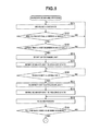
- FIG. 8 is a flow chart ( 1 ) of a process of scanning barcodes.
- FIG. 9 is a flow chart ( 2 ) of the process of scanning barcodes.
- FIG. 10 is a view for explaining a time period needed before a scanning operation starts in the handy terminal.
- FIG. 11 is a view for explaining a resting state, standby state and a reading state in the handy terminal.
- FIG. 1 is a view showing the construction of the handy terminal 1 .
- the handy terminal 1 is provided with an operation key 12 A (operation unit), a trigger key 12 B (operation unit), a displaying unit 14 and a scanner unit 17 .
- the handy terminal 1 can be also used as an information terminal such as a smart phone, a tablet PC (Personal Computer), a laptop PC and PDA (Personal Digital Assistance).
- the operation key 12 A is a key pad for receiving an input operation and is used by a user to perform an input operation to input an instruction. The user performs the input operation to enter numerals and/or characters and to read various functions.
- the trigger key 12 B is a key pad for receiving a trigger-input of scanned barcodes. While the trigger key 12 B is being operated, the scanner unit 17 emits laser light toward barcodes to scan them, as will be described later.
- a sensor 19 for measuring a distance is provided on the trigger key 12 B or is provided in the vicinity of the trigger key 12 B.
- the distance measuring sensor 19 detects the user's finger (or hand) approached within a predetermined distance from the trigger key 12 B.
- the displaying unit 14 consists of LCD (Liquid Crystal Display) or ELD (Electro Luminescent Display), and serves to display information which is necessary for operating the handy terminal 1 . Further, the displaying unit 14 can be composed of a tough panel of a pressure sensitive type or an electrostatic type to be used for receiving an input operation.
- LCD Liquid Crystal Display
- ELD Electro Luminescent Display
- the scanner unit 17 is a laser scanner for reading an one-dimensional barcode and is provided with a light emitting unit, a light receiving unit, a gain circuit, and a binary processing circuit. More specifically, the light emitting unit of the scanner unit 17 emits light toward the barcodes and the light receiving unit receives the light reflected from the barcodes and converts the received light into an electronic signal.
- the gain circuit amplifies the electric signal and the binary processing circuit binarizes the electric signal to binary data, whereby the scanner unit 17 outputs the binary data.
- the scanner unit 17 is controlled to be either in a rest state, a standby state or in a reading state.
- the scanner unit 17 is controlled in accordance with the user's convenience to be kept in one of the three states, and is allowed to start the barcode reading operation quickly with least power consumption.
- FIG. 2 is a view showing the physical configuration of the handy terminal 1 .
- the handy terminal 1 comprises CPU (Central Processing Unit) 11 , an operation unit 12 , RAM (Random Access Memory) 13 , the displaying unit 14 , a memory unit 15 , a communication unit 16 , the scanner unit 17 , a time counting unit 18 , and the distance measuring sensor (measuring unit) 19 .
- CPU Central Processing Unit
- RAM Random Access Memory
- the displaying unit 14 a memory unit 15 , a communication unit 16 , the scanner unit 17 , a time counting unit 18 , and the distance measuring sensor (measuring unit) 19 .
- These units of the handy terminal 1 are connected to each other through a bus 1 A.
- the displaying unit 14 and the scanner unit 17 have been described above, and therefore further their description will be omitted hereafter.
- a processor of the handy terminal 1 can be used as the CPU 11 .
- the CPU 11 serves to control operation of the various units of the handy terminal 1 .
- the CPU 11 reads the designated one out of a system program and application programs stored in the memory unit 15 to the RAM 13 , and executes the read program to various processes.
- the operation unit 12 includes the operation key 12 A and the trigger key 12 B.
- the operation unit 12 also includes a touch panel provided so as to cover the whole surface of the displaying unit 14 .
- the RAM 13 is a volatile memory for storing information temporarily and has a work area for storing various sorts of data and programs.
- the memory unit 15 has a configuration including ROM (Read Only Memory) and a flash memory, and stores various sorts of information such as programs and application programs in addition to the operation system. It is possible for the memory unit 15 to have a configuration including a detachable and portable memory such as an SD card and IC (Integrated Circuit) card. Further, it is possible for the memory unit 15 to include a memory area of a predetermined external server while the memory unit 15 is connected with the external server through a network with the communication function.
- ROM Read Only Memory
- flash memory stores various sorts of information such as programs and application programs in addition to the operation system. It is possible for the memory unit 15 to have a configuration including a detachable and portable memory such as an SD card and IC (Integrated Circuit) card. Further, it is possible for the memory unit 15 to include a memory area of a predetermined external server while the memory unit 15 is connected with the external server through a network with the communication function.
- the communication unit 16 is provided with an antenna used for radio communication, a modulation unit for modulating a sending signal, and a demodulation unit for demodulating a received signal, and performs radio communication with an access point on a communication network.
- the time counting unit 18 is a time piece (clock) for counting a real time.
- the time counting unit 18 provides the CPU 11 with time information including a date and a time.
- the time counting unit 18 has a stop-watch function of measuring a lapsed time.
- the distance measuring sensor 19 serves to measure a distance between the operation unit 12 and an operating body.
- the distance measuring sensor 19 measures a distance to the finger of the user who is going to operate the trigger key 12 B.
- the distance measuring sensor 19 uses the principle of measurement in Triangulation and Time of Flight to obtain distance information.
- a light source in the distance measuring sensor 19 emits light to the operating body and a light receiving element receives the light reflected from the operating body.
- the received light is subjected to evaluation and calculation, whereby the received light is converted to distance information representing a distance between the sensor 19 and the operating body.
- the distance information is supplied to the CPU 11 .
- the distance measuring sensor 19 is not restricted to the above, but a sensor of an electrostatic capacitance type can be used as the distance measuring sensor 19 .
- the distance measuring sensor 19 is provided on the trigger key 12 B or in the vicinity of the trigger key 12 B, it is preferable to compose the distance measuring sensor 19 from a transparent member or to make it such that the sensor 19 will allow light to pass through it's own body.
- the distance measuring sensor 19 made in the above manner the light can be emitted to the user's finger from the trigger key 12 B. Further, the light can be used for enhancing convenience in operation of the handy terminal 1 , for improving its external appearance, and for making good use of power in the handy terminal 1 .
- FIG. 3 is a view showing a block diagram (functional configuration) of the handy terminal 1 .
- the handy terminal 1 comprises a distance measuring unit 31 , a measured value judging unit 32 , a trigger-input judging unit 33 , and a scanner controlling unit 34 .
- the distance measuring unit 31 uses the distance measuring sensor 19 to measure a distance between the operation unit 12 and the operating body, and supplies the measured distance to the CPU 11 .
- a distance between the operation unit 12 and the finger of the user who is going to operate the trigger key 12 B is measured and the measured distance is output to the CPU 11 .
- the measured value judging unit 32 judges whether the distance measured by the distance measuring unit 31 falls within a prescribed range. In the present handy terminal 1 , the measured value judging unit 32 judges whether the distance between the operation unit 12 and the finger of the user who is going to operate the trigger key 12 B falls within the prescribed range.
- the trigger-input judging unit 33 judges whether the user has operated the trigger key 12 B.
- the scanner controlling unit 34 controls operation of the scanner unit 17 in accordance with outputs from the measured value judging unit 32 and the trigger-input judging unit 33 .
- the controlling operation of the scanner controlling unit 34 will be described with reference to FIG. 4 and the following drawings in detail.
- FIG. 4 is a view showing the transition in state of the scanner unit 17 .
- the scanner unit 17 is controlled to be maintained either in the resting state, the standby state or in the reading state. It is determined based on the outputs of the measured value judging unit 32 and the trigger-input judging unit 33 , in which state the scanner unit 17 is maintained.
- the resting state of the scanner unit 17 will be described.
- the scanner unit 17 is controlled to be in the resting state.
- the scanner unit 17 in the resting state is out of operation and will consume the least power.
- the handy terminal 1 will take time before the scanner unit 17 in the resting state starts the barcode scanning operation, since it is required to start up the scanner unit 17 to emit laser light.
- FIG. 5 is a view showing the handy terminal 1 with the scanner unit 17 maintained in the resting state.
- FIG. 5 is a cross-sectional view of the handy terminal 1 , which illustrates the scanner unit 17 and the distance measuring sensor 19 mounted on a substrate 51 .
- the displaying unit 14 and the operation key 12 A are omitted therefrom.
- the trigger key 12 B is not operated and no operating body has been detected within a prescribed range defined based on the position of the distance measuring sensor 19 . More specifically, the measured value judging unit 32 determines that the distance between the trigger key 12 B and the user's finger does not fall within the prescribed range. Therefore, the scanner unit 17 is not driven and maintained in the resting state.
- the standby state of the scanner unit 17 will be described with reference to FIG. 4 .
- the scanner unit 17 is controlled to be in the standby state.
- the scanner unit 17 in the standby state is driven but does not emit laser light.
- the power will be saved by an amount corresponding to power consumption required for emitting laser light.
- FIG. 6 is a view showing the handy terminal 1 with the scanner unit 17 maintained in the standby state.
- the trigger key 12 B is not operated by the user but an operating body (the user's finger 61 ) has been detected within the prescribed range defined based on the position of the distance measuring sensor 19 . More specifically, the measured value judging unit 32 determines that the distance between the trigger key 12 B and the user's finger 61 falls within the prescribed range. Therefore, the scanner unit 17 is driven and kept in the standby state, in which no laser light is emitted.
- the reading state of the scanner unit 17 will be described with reference to FIG. 4 .
- the scanner unit 17 is controlled to be in the reading state.
- the scanner unit 17 in the reading state is driven to emit laser light.
- the power is consumed for emitting laser light to read barcodes.
- FIG. 7 is a view showing the handy terminal 1 with the scanner unit 17 maintained in the reading state.
- the user operates the trigger key 12 B of the handy terminal 1 with his/her finger 61 . Therefore, the scanner unit 17 is driven to emit laser light, in other words, the scanner unit 17 is in the reading state.
- FIG. 8 and FIG. 9 are flow charts of the process of scanning barcodes.
- the distance measuring unit 31 measures a distance between the operation unit 12 and the operating body (for example, user's finger or hand) based on information output from the distance measuring sensor 19 (step S 11 in FIG. 8 ).
- the measured value judging unit 32 judges whether the distance between the operation unit 12 and the user's finger 61 , measured by the distance measuring unit 31 , falls within the prescribed range (step S 12 ).
- the time counting unit 18 starts counting a lapsed time and supplies the counted lapsed time to the scanner controlling unit 34 .
- the scanner controlling unit 34 judges whether the lapsed time output from the time counting unit 18 is not shorter than 0.5 seconds (step S 13 ).
- step S 13 when the user's finger 61 has come in the prescribed range even though the user does not want to scan barcodes, it will be possible to prevent the scanner unit 17 from being driven.
- the lapsed time is not shorter than 0.5 seconds, but the lapsed time may be set to another value appropriately. Further, the process at step S 13 can be omitted. In the flow chart of FIG. 8 , with the process of step S 13 omitted, when it is determined that the distance between the operation unit 12 and the user's finger 61 falls within the prescribed range (YES at step S 12 ), the process advances to step S 14 .
- the scanner controlling unit 34 starts up the scanner unit 17 (step S 14 ) and brings the scanner unit 17 to the standby state (step S 15 ). Therefore, even though the user does not operate the trigger key 12 B, when it is detected that the user's finger 61 has come close the trigger key 12 B, the scanner unit 17 will be driven.
- the scanner controlling unit 34 ceases driving the scanner unit 17 , bringing the scanner unit 17 to the resting state, that is, returning to step S 11 .
- the CPU 11 judges whether the trigger key 19 has been operated by the user (step S 16 ). In other words, the CPU 11 works as the trigger-input judging unit 33 .
- the CPU 11 When it is determined that the trigger key 19 has not been operated by the user (NO at step S 16 ), the CPU 11 repeatedly performs the process at step S 16 and the scanner unit 17 stays in the standby state, until the trigger key 12 B will be operated by the user. Meanwhile, when it is determined that the trigger key 19 has been operated by the user (YES at step S 16 ), the CPU 11 controls the scanner unit 17 to emit laser light (step S 17 ), bringing the scanner unit 17 to the reading state (step S 18 ). In other words, the CPU 11 performs the function of the scanner controlling unit 34 .
- the scanner unit 17 When the scanner unit 17 is brought to the reading state, it is possible for the scanner unit 17 to scan barcodes by making the scanner unit 17 emit laser light toward the barcodes which the user wants to read (step S 19 ).
- the CPU 11 judges whether the user has finished operation of the trigger key 12 B (step S 21 in FIG. 9 ). In other words, the CPU 11 performs the function of the trigger-input judging unit 33 .
- the CPU 11 controls the scanner unit 17 to cease emitting laser light (step S 22 ), bringing the scanner unit 17 to the standby state (step S 23 ). Meanwhile, when it is determined that the user has not finished operation of the trigger key 12 B (NO at step S 21 ), the CPU 11 repeatedly performs the process at step S 21 until the user will finish operation of the trigger key 12 B. In other words, the CPU 11 performs the function of the scanner controlling unit 34 .
- the CPU 11 instructs the distance measuring sensor 19 to measure a distance from the operation unit 12 to the user's finger 61 (step S 24 ). In other words, the CPU 11 performs the function of the distance measuring unit 31 . Further, the CPU 11 judges whether the distance between the operation unit 12 and the user's finger 61 falls within the prescribed range (step S 25 ). In other words, the CPU 11 works as the measured value judging unit 32 .
- the CPU 11 controls the scanner unit 17 to cease its operation (step S 26 ), bringing the scanner unit 15 to the resting state (step S 27 ), and finishes the process of scanning barcodes. Meanwhile, when it is determined that the distance between the operation unit 12 and the user's finger 61 falls within the prescribed range (YES at step S 25 ), the CPU 11 repeatedly performs the process at step S 25 until it will be determined that the distance between the operation 12 and the user's finger 61 does not fall within the prescribed range. In other words, the CPU 11 performs the function of the scanner controlling unit 34 .
- FIG. 10 Effects of the handy terminal 1 will be described with reference to FIG. 10 and FIG. 11 .
- FIG. 10 a time of starting a reading operation by the handy terminal 1 will be described.
- the handy terminal 1 When the handy terminal 1 according to the present embodiment of the invention scans barcodes, upon confirmation by the distance measuring sensor 19 that the user's finger 61 has come close, the CPU 11 starts up the scanner unit 17 to bring the unit 17 to the standby state, as shown in FIG. 10 . Therefore, the scanner unit 17 is maintained in the standby state after the scanner unit 17 has been driven until the trigger key 12 B is operated.
- the time period in which the scanner unit 17 is maintained in the standby state is indicated as a “standby period” in FIG. 10 .
- the scanner unit 17 emits laser light and comes in the reading state, in which the scanner unit 17 can scan barcodes. Since the scanner unit 12 has been driven and is in the standby state at the time when the trigger key 12 B is operated, there is no need for the scanner unit 17 to wait for by the “startup time”. Therefore, at the time of 101 in FIG. 10 the scanner unit 17 has been ready for performing operation of scanning barcodes.
- the handy terminal 1 can start barcode-reading operation in a comparably short time.
- the reading state and the standby state of a device for reading barcodes will be described with reference to FIG. 11 .
- FIG. 11 is a view showing a state transition of a barcode scanner which scans barcodes (for instance, three barcodes).
- the handy terminal 1 reads three barcodes as shown in FIG. 11 , it is possible to keep the scanner unit 17 in the standby state by interrupting operation of the trigger key 12 B while the handy terminal 1 is scanning barcodes. More specifically, the scanner unit 17 emits laser light only while the handy terminal 1 is scanning barcodes. Meanwhile, even though the scanner unit 17 is driven but no laser light is emitted.
- the scanner unit 17 is controlled to be in the resting state, the standby state, or in the reading state, and the scanner unit 17 emits laser light only when needed. Therefore, power consumption can be reduced in the handy terminal 1 .
- the handy terminal 1 judges whether a distance between the operation unit 12 and the operating body falls within a prescribed range, and drives and brings the scanner unit 17 to the standby state for receiving a trigger-input to perform a barcode scanning operation, when it is determined that the distance between the operation unit 12 and the operating body falls within a prescribed range. In other words, this means that the handy terminal 1 has judging means and controlling means.
- the handy terminal 1 realizes a barcode reading device and program which consume less power and can start the barcode reading operation in a short time.
- the handy terminal 1 judges whether a distance between the trigger key 12 B for receiving the trigger-input and the operating body falls within the prescribed range. Therefore the handy terminal 1 can drive the barcode scanner before the user operates the trigger key 12 B.
- the handy terminal 1 When the operating body moves away from the prescribed range, while the handy terminal 1 is driving the barcode scanner upon confirming that the distance to the operating body falls within the prescribed range, the handy terminal 1 ceases driving the barcode scanner. Therefore, it is possible to use the scanner unit 117 only when needed.
- the handy terminal 1 counts a lapsed time after the time when it is determined that the distance to the operating body falls within the prescribed range, and drives and brings the scanner unit 17 to the standby state for receiving a trigger-input, when the lapsed time has reached a prescribed time period. Therefore, it is possible to prevent the scanner unit 17 from being driven independently of the user's intention.
- the embodiment of the invention has been explained with a specific example using the user's finger as the operating body, wherein the distance measuring sensor 19 measures a distance between the trigger key 12 B and the user's finger, but other part of the user in place of his/her finger can be used. Further, other device can be used in place of the distance measuring sensor 19 to measure the distance.
- the scanner unit 17 is controlled to be maintained in three states: the resting state, the standby state and the reading state.
- the states in which the scanner unit 17 is controlled to be maintained are not restricted to the above three states. It is possible to control the scanner unit 17 based on a distance measured by the distance measuring sensor 19 , to which state the scanner unit 17 is brought, the resting state, the standby state or the reading state.
- the distance measuring sensor 19 measures a distance between the operation unit 12 and the operating body to judge whether the distance falls within the prescribed range.
- a photoelectric sensor for detecting the operating body there will be no need for the distance measuring sensor 19 to measure the distance to control the scanner unit 17 .
- the distance measuring sensor 19 is mounted on the substrate 51 just below the trigger key 12 B ( FIG. 5 to FIG. 7 ), but the distance measuring sensor 19 may be provided on other position.
- the unit having CPU 11 , RAM 13 , and the memory unit 15 for performing the process of scanning barcodes, by using an average computer system in place of a specific system.
- a computer readable recording medium such as a flexible disk drive, CD-ROM and DVD-ROM, with a computer program for performing the above process, stored thereon, is distributed, and the program, when installed on a computer, instructs the computer to perform the process of scanning barcodes.
- the unit for performing the process of scanning barcodes may be realized by the average computer system.
- the computer program through the communication network. For example, it is possible to put up the computer program on a notice board of the communication network to deliver the computer program through the network.
- the computer executes the delivered computer program under operation of the OS, thereby performing the process for scanning barcodes.
Landscapes
- Physics & Mathematics (AREA)
- Engineering & Computer Science (AREA)
- Electromagnetism (AREA)
- Health & Medical Sciences (AREA)
- General Health & Medical Sciences (AREA)
- Toxicology (AREA)
- Artificial Intelligence (AREA)
- Computer Vision & Pattern Recognition (AREA)
- General Physics & Mathematics (AREA)
- Theoretical Computer Science (AREA)
- Cash Registers Or Receiving Machines (AREA)
- Power Sources (AREA)
Abstract
Description
Claims (7)
Applications Claiming Priority (2)
| Application Number | Priority Date | Filing Date | Title |
|---|---|---|---|
| JP2016207499A JP6708095B2 (en) | 2016-10-24 | 2016-10-24 | Bar code reader and program |
| JP2016-207499 | 2016-10-24 |
Publications (2)
| Publication Number | Publication Date |
|---|---|
| US20180114044A1 US20180114044A1 (en) | 2018-04-26 |
| US10402613B2 true US10402613B2 (en) | 2019-09-03 |
Family
ID=61969726
Family Applications (1)
| Application Number | Title | Priority Date | Filing Date |
|---|---|---|---|
| US15/699,885 Active US10402613B2 (en) | 2016-10-24 | 2017-09-08 | Apparatus and method for reading barcodes and recording medium |
Country Status (2)
| Country | Link |
|---|---|
| US (1) | US10402613B2 (en) |
| JP (1) | JP6708095B2 (en) |
Families Citing this family (1)
| Publication number | Priority date | Publication date | Assignee | Title |
|---|---|---|---|---|
| JP2022126441A (en) * | 2021-02-18 | 2022-08-30 | ブラザー工業株式会社 | server and computer program for server |
Citations (9)
| Publication number | Priority date | Publication date | Assignee | Title |
|---|---|---|---|---|
| JPH0620086A (en) | 1991-08-30 | 1994-01-28 | Nec Home Electron Ltd | Bar code reader and control method |
| US20030121981A1 (en) * | 2001-12-28 | 2003-07-03 | Michael Slutsky | Lighthouse ASIC |
| US20030222150A1 (en) * | 2002-05-30 | 2003-12-04 | Masaki Sato | Inexpensive and easy-to-handle structure of optical information reading apparatus |
| US20060043193A1 (en) * | 2004-08-30 | 2006-03-02 | Brock Christopher W | Combination barcode imaging/decoding and real-time video capture system |
| WO2007145003A1 (en) | 2006-06-14 | 2007-12-21 | Mitsubishi Electric Corporation | In-vehicle information device |
| US20080292141A1 (en) * | 2007-05-25 | 2008-11-27 | Ming Yu | Method and system for triggering a device with a range finder based on aiming pattern |
| US20110000966A1 (en) * | 2009-07-06 | 2011-01-06 | Liu Shu-Shien | Barcode reading device |
| US20120181338A1 (en) * | 2011-01-18 | 2012-07-19 | Datalogic ADC, Inc. | Systems and methods for illuminating a scan volume of an optical code reader |
| US9117129B1 (en) | 2015-02-05 | 2015-08-25 | Symbol Technologies, Llc | Predictive triggering in an electronic device |
-
2016
- 2016-10-24 JP JP2016207499A patent/JP6708095B2/en not_active Expired - Fee Related
-
2017
- 2017-09-08 US US15/699,885 patent/US10402613B2/en active Active
Patent Citations (9)
| Publication number | Priority date | Publication date | Assignee | Title |
|---|---|---|---|---|
| JPH0620086A (en) | 1991-08-30 | 1994-01-28 | Nec Home Electron Ltd | Bar code reader and control method |
| US20030121981A1 (en) * | 2001-12-28 | 2003-07-03 | Michael Slutsky | Lighthouse ASIC |
| US20030222150A1 (en) * | 2002-05-30 | 2003-12-04 | Masaki Sato | Inexpensive and easy-to-handle structure of optical information reading apparatus |
| US20060043193A1 (en) * | 2004-08-30 | 2006-03-02 | Brock Christopher W | Combination barcode imaging/decoding and real-time video capture system |
| WO2007145003A1 (en) | 2006-06-14 | 2007-12-21 | Mitsubishi Electric Corporation | In-vehicle information device |
| US20080292141A1 (en) * | 2007-05-25 | 2008-11-27 | Ming Yu | Method and system for triggering a device with a range finder based on aiming pattern |
| US20110000966A1 (en) * | 2009-07-06 | 2011-01-06 | Liu Shu-Shien | Barcode reading device |
| US20120181338A1 (en) * | 2011-01-18 | 2012-07-19 | Datalogic ADC, Inc. | Systems and methods for illuminating a scan volume of an optical code reader |
| US9117129B1 (en) | 2015-02-05 | 2015-08-25 | Symbol Technologies, Llc | Predictive triggering in an electronic device |
Non-Patent Citations (1)
| Title |
|---|
| Japanese Office Action dated May 14, 2019 (and English translation thereof) issued in counterpart Japanese Application No. 2016-207499. |
Also Published As
| Publication number | Publication date |
|---|---|
| JP2018072862A (en) | 2018-05-10 |
| JP6708095B2 (en) | 2020-06-10 |
| US20180114044A1 (en) | 2018-04-26 |
Similar Documents
| Publication | Publication Date | Title |
|---|---|---|
| US11353319B2 (en) | Method for a mobile dimensioning device to use a dynamic accuracy compatible with NIST standard | |
| US10715974B2 (en) | Methods for provisioning a wireless beacon | |
| US20230074855A1 (en) | Registration apparatus, registration system and registration method | |
| US11263847B2 (en) | Door lock apparatus, electronic device, method for unlocking digital door lock apparatus by using electronic device | |
| US10810412B2 (en) | Method, system and apparatus for gesture-based configuration of paired scanner | |
| EP3319011A1 (en) | Fingerprint acquisition device and method, terminal apparatus and method for controlling screen to turn on and off | |
| JPH0628380A (en) | Paperless luggage tracking system | |
| US20180053027A1 (en) | Method for reading indicia off a display of a mobile device | |
| CN104851215B (en) | Printing equipment reads system and POS system | |
| CN101799880A (en) | Information processing apparatus, information processing method, program and information processing system | |
| KR20190134378A (en) | Electronic device, blood pressure measuring method of electronic device, blood pressure measuring system | |
| US10402613B2 (en) | Apparatus and method for reading barcodes and recording medium | |
| CN110678869B (en) | Reading system and camera | |
| WO2002031749A1 (en) | Lcd barcode scanner with capability of scanning lcd barcode | |
| JP2009160746A (en) | Information processing device | |
| JP2000137773A (en) | Handy type reader/writer for id tag | |
| JP5747566B2 (en) | Information terminal and information system | |
| CN114444527B (en) | A code scanning identification method, device, equipment and medium | |
| JP7120280B2 (en) | Terminal device and program | |
| US6382512B1 (en) | Signal reading control apparatus for barcode scanner | |
| JP6977435B2 (en) | Program, information processing terminal and setting support method | |
| WO2022070233A1 (en) | Communication control apparatus, operation terminal, device operation system, communication control method, operation terminal control method, and program | |
| US6382509B1 (en) | Signal reading control method for barcode scanner | |
| US20240385791A1 (en) | Image forming apparatus and execution method | |
| JP5811331B2 (en) | Image forming apparatus, authentication print method, authentication print program, operation mode switching method, and operation mode switching program |
Legal Events
| Date | Code | Title | Description |
|---|---|---|---|
| AS | Assignment |
Owner name: CASIO COMPUTER CO., LTD., JAPAN Free format text: ASSIGNMENT OF ASSIGNORS INTEREST;ASSIGNOR:MORIYAMA, TEPPEI;REEL/FRAME:043538/0286 Effective date: 20170825 |
|
| FEPP | Fee payment procedure |
Free format text: ENTITY STATUS SET TO UNDISCOUNTED (ORIGINAL EVENT CODE: BIG.); ENTITY STATUS OF PATENT OWNER: LARGE ENTITY |
|
| STPP | Information on status: patent application and granting procedure in general |
Free format text: FINAL REJECTION MAILED |
|
| STPP | Information on status: patent application and granting procedure in general |
Free format text: NOTICE OF ALLOWANCE MAILED -- APPLICATION RECEIVED IN OFFICE OF PUBLICATIONS |
|
| STPP | Information on status: patent application and granting procedure in general |
Free format text: AWAITING TC RESP., ISSUE FEE NOT PAID |
|
| STPP | Information on status: patent application and granting procedure in general |
Free format text: PUBLICATIONS -- ISSUE FEE PAYMENT RECEIVED |
|
| STPP | Information on status: patent application and granting procedure in general |
Free format text: PUBLICATIONS -- ISSUE FEE PAYMENT VERIFIED |
|
| STCF | Information on status: patent grant |
Free format text: PATENTED CASE |
|
| MAFP | Maintenance fee payment |
Free format text: PAYMENT OF MAINTENANCE FEE, 4TH YEAR, LARGE ENTITY (ORIGINAL EVENT CODE: M1551); ENTITY STATUS OF PATENT OWNER: LARGE ENTITY Year of fee payment: 4 |