US10399166B2 - System and method for machining workpiece of lattice structure and article machined therefrom - Google Patents
System and method for machining workpiece of lattice structure and article machined therefrom Download PDFInfo
- Publication number
- US10399166B2 US10399166B2 US15/196,165 US201615196165A US10399166B2 US 10399166 B2 US10399166 B2 US 10399166B2 US 201615196165 A US201615196165 A US 201615196165A US 10399166 B2 US10399166 B2 US 10399166B2
- Authority
- US
- United States
- Prior art keywords
- workpiece
- electrodes
- electrode
- voltage
- lattice structure
- Prior art date
- Legal status (The legal status is an assumption and is not a legal conclusion. Google has not performed a legal analysis and makes no representation as to the accuracy of the status listed.)
- Active, expires
Links
Images


Classifications
-
- B—PERFORMING OPERATIONS; TRANSPORTING
- B23—MACHINE TOOLS; METAL-WORKING NOT OTHERWISE PROVIDED FOR
- B23H—WORKING OF METAL BY THE ACTION OF A HIGH CONCENTRATION OF ELECTRIC CURRENT ON A WORKPIECE USING AN ELECTRODE WHICH TAKES THE PLACE OF A TOOL; SUCH WORKING COMBINED WITH OTHER FORMS OF WORKING OF METAL
- B23H3/00—Electrochemical machining, i.e. removing metal by passing current between an electrode and a workpiece in the presence of an electrolyte
- B23H3/04—Electrodes specially adapted therefor or their manufacture
-
- B—PERFORMING OPERATIONS; TRANSPORTING
- B22—CASTING; POWDER METALLURGY
- B22F—WORKING METALLIC POWDER; MANUFACTURE OF ARTICLES FROM METALLIC POWDER; MAKING METALLIC POWDER; APPARATUS OR DEVICES SPECIALLY ADAPTED FOR METALLIC POWDER
- B22F10/00—Additive manufacturing of workpieces or articles from metallic powder
- B22F10/60—Treatment of workpieces or articles after build-up
- B22F10/62—Treatment of workpieces or articles after build-up by chemical means
-
- B—PERFORMING OPERATIONS; TRANSPORTING
- B22—CASTING; POWDER METALLURGY
- B22F—WORKING METALLIC POWDER; MANUFACTURE OF ARTICLES FROM METALLIC POWDER; MAKING METALLIC POWDER; APPARATUS OR DEVICES SPECIALLY ADAPTED FOR METALLIC POWDER
- B22F10/00—Additive manufacturing of workpieces or articles from metallic powder
- B22F10/60—Treatment of workpieces or articles after build-up
- B22F10/66—Treatment of workpieces or articles after build-up by mechanical means
-
- B—PERFORMING OPERATIONS; TRANSPORTING
- B22—CASTING; POWDER METALLURGY
- B22F—WORKING METALLIC POWDER; MANUFACTURE OF ARTICLES FROM METALLIC POWDER; MAKING METALLIC POWDER; APPARATUS OR DEVICES SPECIALLY ADAPTED FOR METALLIC POWDER
- B22F3/00—Manufacture of workpieces or articles from metallic powder characterised by the manner of compacting or sintering; Apparatus specially adapted therefor ; Presses and furnaces
- B22F3/24—After-treatment of workpieces or articles
-
- B—PERFORMING OPERATIONS; TRANSPORTING
- B22—CASTING; POWDER METALLURGY
- B22F—WORKING METALLIC POWDER; MANUFACTURE OF ARTICLES FROM METALLIC POWDER; MAKING METALLIC POWDER; APPARATUS OR DEVICES SPECIALLY ADAPTED FOR METALLIC POWDER
- B22F5/00—Manufacture of workpieces or articles from metallic powder characterised by the special shape of the product
- B22F5/009—Manufacture of workpieces or articles from metallic powder characterised by the special shape of the product of turbine components other than turbine blades
-
- B—PERFORMING OPERATIONS; TRANSPORTING
- B22—CASTING; POWDER METALLURGY
- B22F—WORKING METALLIC POWDER; MANUFACTURE OF ARTICLES FROM METALLIC POWDER; MAKING METALLIC POWDER; APPARATUS OR DEVICES SPECIALLY ADAPTED FOR METALLIC POWDER
- B22F5/00—Manufacture of workpieces or articles from metallic powder characterised by the special shape of the product
- B22F5/04—Manufacture of workpieces or articles from metallic powder characterised by the special shape of the product of turbine blades
-
- B—PERFORMING OPERATIONS; TRANSPORTING
- B22—CASTING; POWDER METALLURGY
- B22F—WORKING METALLIC POWDER; MANUFACTURE OF ARTICLES FROM METALLIC POWDER; MAKING METALLIC POWDER; APPARATUS OR DEVICES SPECIALLY ADAPTED FOR METALLIC POWDER
- B22F5/00—Manufacture of workpieces or articles from metallic powder characterised by the special shape of the product
- B22F5/10—Manufacture of workpieces or articles from metallic powder characterised by the special shape of the product of articles with cavities or holes, not otherwise provided for in the preceding subgroups
-
- B—PERFORMING OPERATIONS; TRANSPORTING
- B23—MACHINE TOOLS; METAL-WORKING NOT OTHERWISE PROVIDED FOR
- B23H—WORKING OF METAL BY THE ACTION OF A HIGH CONCENTRATION OF ELECTRIC CURRENT ON A WORKPIECE USING AN ELECTRODE WHICH TAKES THE PLACE OF A TOOL; SUCH WORKING COMBINED WITH OTHER FORMS OF WORKING OF METAL
- B23H3/00—Electrochemical machining, i.e. removing metal by passing current between an electrode and a workpiece in the presence of an electrolyte
- B23H3/04—Electrodes specially adapted therefor or their manufacture
- B23H3/06—Electrode material
-
- B—PERFORMING OPERATIONS; TRANSPORTING
- B23—MACHINE TOOLS; METAL-WORKING NOT OTHERWISE PROVIDED FOR
- B23H—WORKING OF METAL BY THE ACTION OF A HIGH CONCENTRATION OF ELECTRIC CURRENT ON A WORKPIECE USING AN ELECTRODE WHICH TAKES THE PLACE OF A TOOL; SUCH WORKING COMBINED WITH OTHER FORMS OF WORKING OF METAL
- B23H9/00—Machining specially adapted for treating particular metal objects or for obtaining special effects or results on metal objects
- B23H9/001—Disintegrating
-
- B—PERFORMING OPERATIONS; TRANSPORTING
- B23—MACHINE TOOLS; METAL-WORKING NOT OTHERWISE PROVIDED FOR
- B23H—WORKING OF METAL BY THE ACTION OF A HIGH CONCENTRATION OF ELECTRIC CURRENT ON A WORKPIECE USING AN ELECTRODE WHICH TAKES THE PLACE OF A TOOL; SUCH WORKING COMBINED WITH OTHER FORMS OF WORKING OF METAL
- B23H9/00—Machining specially adapted for treating particular metal objects or for obtaining special effects or results on metal objects
- B23H9/02—Trimming or deburring
-
- B—PERFORMING OPERATIONS; TRANSPORTING
- B23—MACHINE TOOLS; METAL-WORKING NOT OTHERWISE PROVIDED FOR
- B23H—WORKING OF METAL BY THE ACTION OF A HIGH CONCENTRATION OF ELECTRIC CURRENT ON A WORKPIECE USING AN ELECTRODE WHICH TAKES THE PLACE OF A TOOL; SUCH WORKING COMBINED WITH OTHER FORMS OF WORKING OF METAL
- B23H9/00—Machining specially adapted for treating particular metal objects or for obtaining special effects or results on metal objects
- B23H9/10—Working turbine blades or nozzles
-
- B—PERFORMING OPERATIONS; TRANSPORTING
- B23—MACHINE TOOLS; METAL-WORKING NOT OTHERWISE PROVIDED FOR
- B23K—SOLDERING OR UNSOLDERING; WELDING; CLADDING OR PLATING BY SOLDERING OR WELDING; CUTTING BY APPLYING HEAT LOCALLY, e.g. FLAME CUTTING; WORKING BY LASER BEAM
- B23K26/00—Working by laser beam, e.g. welding, cutting or boring
- B23K26/34—Laser welding for purposes other than joining
- B23K26/342—Build-up welding
-
- B—PERFORMING OPERATIONS; TRANSPORTING
- B33—ADDITIVE MANUFACTURING TECHNOLOGY
- B33Y—ADDITIVE MANUFACTURING, i.e. MANUFACTURING OF THREE-DIMENSIONAL [3D] OBJECTS BY ADDITIVE DEPOSITION, ADDITIVE AGGLOMERATION OR ADDITIVE LAYERING, e.g. BY 3D PRINTING, STEREOLITHOGRAPHY OR SELECTIVE LASER SINTERING
- B33Y10/00—Processes of additive manufacturing
-
- B—PERFORMING OPERATIONS; TRANSPORTING
- B33—ADDITIVE MANUFACTURING TECHNOLOGY
- B33Y—ADDITIVE MANUFACTURING, i.e. MANUFACTURING OF THREE-DIMENSIONAL [3D] OBJECTS BY ADDITIVE DEPOSITION, ADDITIVE AGGLOMERATION OR ADDITIVE LAYERING, e.g. BY 3D PRINTING, STEREOLITHOGRAPHY OR SELECTIVE LASER SINTERING
- B33Y30/00—Apparatus for additive manufacturing; Details thereof or accessories therefor
-
- B—PERFORMING OPERATIONS; TRANSPORTING
- B33—ADDITIVE MANUFACTURING TECHNOLOGY
- B33Y—ADDITIVE MANUFACTURING, i.e. MANUFACTURING OF THREE-DIMENSIONAL [3D] OBJECTS BY ADDITIVE DEPOSITION, ADDITIVE AGGLOMERATION OR ADDITIVE LAYERING, e.g. BY 3D PRINTING, STEREOLITHOGRAPHY OR SELECTIVE LASER SINTERING
- B33Y40/00—Auxiliary operations or equipment, e.g. for material handling
- B33Y40/20—Post-treatment, e.g. curing, coating or polishing
-
- B—PERFORMING OPERATIONS; TRANSPORTING
- B33—ADDITIVE MANUFACTURING TECHNOLOGY
- B33Y—ADDITIVE MANUFACTURING, i.e. MANUFACTURING OF THREE-DIMENSIONAL [3D] OBJECTS BY ADDITIVE DEPOSITION, ADDITIVE AGGLOMERATION OR ADDITIVE LAYERING, e.g. BY 3D PRINTING, STEREOLITHOGRAPHY OR SELECTIVE LASER SINTERING
- B33Y80/00—Products made by additive manufacturing
-
- B—PERFORMING OPERATIONS; TRANSPORTING
- B33—ADDITIVE MANUFACTURING TECHNOLOGY
- B33Y—ADDITIVE MANUFACTURING, i.e. MANUFACTURING OF THREE-DIMENSIONAL [3D] OBJECTS BY ADDITIVE DEPOSITION, ADDITIVE AGGLOMERATION OR ADDITIVE LAYERING, e.g. BY 3D PRINTING, STEREOLITHOGRAPHY OR SELECTIVE LASER SINTERING
- B33Y99/00—Subject matter not provided for in other groups of this subclass
-
- C—CHEMISTRY; METALLURGY
- C25—ELECTROLYTIC OR ELECTROPHORETIC PROCESSES; APPARATUS THEREFOR
- C25F—PROCESSES FOR THE ELECTROLYTIC REMOVAL OF MATERIALS FROM OBJECTS; APPARATUS THEREFOR
- C25F3/00—Electrolytic etching or polishing
- C25F3/16—Polishing
-
- C—CHEMISTRY; METALLURGY
- C25—ELECTROLYTIC OR ELECTROPHORETIC PROCESSES; APPARATUS THEREFOR
- C25F—PROCESSES FOR THE ELECTROLYTIC REMOVAL OF MATERIALS FROM OBJECTS; APPARATUS THEREFOR
- C25F7/00—Constructional parts, or assemblies thereof, of cells for electrolytic removal of material from objects; Servicing or operating
-
- B—PERFORMING OPERATIONS; TRANSPORTING
- B22—CASTING; POWDER METALLURGY
- B22F—WORKING METALLIC POWDER; MANUFACTURE OF ARTICLES FROM METALLIC POWDER; MAKING METALLIC POWDER; APPARATUS OR DEVICES SPECIALLY ADAPTED FOR METALLIC POWDER
- B22F10/00—Additive manufacturing of workpieces or articles from metallic powder
- B22F10/20—Direct sintering or melting
- B22F10/28—Powder bed fusion, e.g. selective laser melting [SLM] or electron beam melting [EBM]
-
- B—PERFORMING OPERATIONS; TRANSPORTING
- B22—CASTING; POWDER METALLURGY
- B22F—WORKING METALLIC POWDER; MANUFACTURE OF ARTICLES FROM METALLIC POWDER; MAKING METALLIC POWDER; APPARATUS OR DEVICES SPECIALLY ADAPTED FOR METALLIC POWDER
- B22F3/00—Manufacture of workpieces or articles from metallic powder characterised by the manner of compacting or sintering; Apparatus specially adapted therefor ; Presses and furnaces
- B22F3/24—After-treatment of workpieces or articles
- B22F2003/241—Chemical after-treatment on the surface
-
- B—PERFORMING OPERATIONS; TRANSPORTING
- B22—CASTING; POWDER METALLURGY
- B22F—WORKING METALLIC POWDER; MANUFACTURE OF ARTICLES FROM METALLIC POWDER; MAKING METALLIC POWDER; APPARATUS OR DEVICES SPECIALLY ADAPTED FOR METALLIC POWDER
- B22F3/00—Manufacture of workpieces or articles from metallic powder characterised by the manner of compacting or sintering; Apparatus specially adapted therefor ; Presses and furnaces
- B22F3/24—After-treatment of workpieces or articles
- B22F2003/247—Removing material: carving, cleaning, grinding, hobbing, honing, lapping, polishing, milling, shaving, skiving, turning the surface
-
- B—PERFORMING OPERATIONS; TRANSPORTING
- B22—CASTING; POWDER METALLURGY
- B22F—WORKING METALLIC POWDER; MANUFACTURE OF ARTICLES FROM METALLIC POWDER; MAKING METALLIC POWDER; APPARATUS OR DEVICES SPECIALLY ADAPTED FOR METALLIC POWDER
- B22F2998/00—Supplementary information concerning processes or compositions relating to powder metallurgy
- B22F2998/10—Processes characterised by the sequence of their steps
-
- B22F3/1055—
-
- B—PERFORMING OPERATIONS; TRANSPORTING
- B23—MACHINE TOOLS; METAL-WORKING NOT OTHERWISE PROVIDED FOR
- B23K—SOLDERING OR UNSOLDERING; WELDING; CLADDING OR PLATING BY SOLDERING OR WELDING; CUTTING BY APPLYING HEAT LOCALLY, e.g. FLAME CUTTING; WORKING BY LASER BEAM
- B23K2101/00—Articles made by soldering, welding or cutting
- B23K2101/001—Turbines
-
- B—PERFORMING OPERATIONS; TRANSPORTING
- B23—MACHINE TOOLS; METAL-WORKING NOT OTHERWISE PROVIDED FOR
- B23K—SOLDERING OR UNSOLDERING; WELDING; CLADDING OR PLATING BY SOLDERING OR WELDING; CUTTING BY APPLYING HEAT LOCALLY, e.g. FLAME CUTTING; WORKING BY LASER BEAM
- B23K2103/00—Materials to be soldered, welded or cut
- B23K2103/02—Iron or ferrous alloys
- B23K2103/04—Steel or steel alloys
- B23K2103/05—Stainless steel
-
- B—PERFORMING OPERATIONS; TRANSPORTING
- B23—MACHINE TOOLS; METAL-WORKING NOT OTHERWISE PROVIDED FOR
- B23K—SOLDERING OR UNSOLDERING; WELDING; CLADDING OR PLATING BY SOLDERING OR WELDING; CUTTING BY APPLYING HEAT LOCALLY, e.g. FLAME CUTTING; WORKING BY LASER BEAM
- B23K2103/00—Materials to be soldered, welded or cut
- B23K2103/08—Non-ferrous metals or alloys
- B23K2103/14—Titanium or alloys thereof
-
- B—PERFORMING OPERATIONS; TRANSPORTING
- B23—MACHINE TOOLS; METAL-WORKING NOT OTHERWISE PROVIDED FOR
- B23K—SOLDERING OR UNSOLDERING; WELDING; CLADDING OR PLATING BY SOLDERING OR WELDING; CUTTING BY APPLYING HEAT LOCALLY, e.g. FLAME CUTTING; WORKING BY LASER BEAM
- B23K2103/00—Materials to be soldered, welded or cut
- B23K2103/18—Dissimilar materials
- B23K2103/26—Alloys of Nickel and Cobalt and Chromium
-
- Y—GENERAL TAGGING OF NEW TECHNOLOGICAL DEVELOPMENTS; GENERAL TAGGING OF CROSS-SECTIONAL TECHNOLOGIES SPANNING OVER SEVERAL SECTIONS OF THE IPC; TECHNICAL SUBJECTS COVERED BY FORMER USPC CROSS-REFERENCE ART COLLECTIONS [XRACs] AND DIGESTS
- Y02—TECHNOLOGIES OR APPLICATIONS FOR MITIGATION OR ADAPTATION AGAINST CLIMATE CHANGE
- Y02P—CLIMATE CHANGE MITIGATION TECHNOLOGIES IN THE PRODUCTION OR PROCESSING OF GOODS
- Y02P10/00—Technologies related to metal processing
- Y02P10/25—Process efficiency
-
- Y02P10/295—
Definitions
- Embodiments of the present invention relate generally to a system and a method for machining a workpiece of lattice structure and an article machined therefrom.
- Additive manufacturing is a technology that enables “3D-printing” of workpieces of various materials including metals and plastics.
- a workpiece is built in a layer-by-layer manner.
- each layer of the workpiece may be manufactured by leveling powder and selectively fusing the powder using a high-power laser. After each layer, more powder is added and the laser forms the next layer, simultaneously fusing it to the prior layers.
- the workpiece typically has a rough surface that is improved via post-build process such as grit blasting, grinding, sanding, or polishing to meet industry standards.
- post-build processes can improve surface finish of the workpiece, but cause unwanted thermal or mechanical stresses being transferred to the workpiece.
- surface finish of the workpiece still needs to be improved to mitigate workpiece failures due to conditions such as fracture, low-cycle fatigue, high-cycle fatigue, and coking.
- the workpiece typically have a bulk structure, for example the workpiece is a solid-body workpiece. That is, sometimes, the workpiece is too heavy to meet industry requirements.
- a system for machining a workpiece of a lattice structure includes an electrode of a lattice structure, an electrolyte supply, and a power supply.
- the workpiece and the electrode are intertwined with each other and electrically isolated from each other.
- the electrolyte supply is configured for circulating an electrolyte around and between the workpiece and the electrode.
- the power supply is configured for applying a voltage between the workpiece and the electrode to facilitate smoothing surfaces of the workpiece.
- a method for machining a workpiece of a lattice structure includes: providing an electrode of a lattice structure to be intertwined with the workpiece and be electrically isolated from the workpiece; circulating an electrolyte around and between the workpiece and the electrode; and applying a voltage between the workpiece and the electrode to facilitate smoothing surfaces of the workpiece.
- an article is provided and machined from a workpiece of a lattice structure by a process.
- the process includes: providing an electrode of a lattice structure to be intertwined with the workpiece and be electrically isolated from the workpiece; circulating an electrolyte around and between the workpiece and the electrode; and applying a voltage between the workpiece and the electrode to facilitate smoothing surfaces of the workpiece.
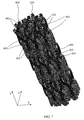
- FIG. 1 is a perspective view of a workpiece of a lattice structure and an electrode.
- FIG. 2 is a schematic view of an additive manufacturing system for manufacturing the workpiece and the electrode of FIG. 1 .
- FIG. 3 is a schematic view of the electrode and an electrochemical machining (ECM) device of a system and the workpiece of FIG. 1 in accordance with a first exemplary embodiment.
- ECM electrochemical machining
- FIG. 4 is a perspective view of an article after machining from the workpiece of FIG. 3 by the ECM device of FIG. 3 .
- FIG. 5 is a perspective view of the workpiece and two electrodes.
- FIG. 6 is a schematic view of two electrodes and an ECM device of a system and the workpiece of FIG. 5 in accordance with a second exemplary embodiment.
- FIG. 7 is a perspective view of a workpiece of another lattice structure and an electrode.
- FIG. 8 is a schematic view of the electrode and an ECM device of a system and the workpiece of FIG. 7 in accordance with a third exemplary embodiment.
- controller may include either a single component or a plurality of components, which are either active and/or passive components and may be optionally connected or otherwise coupled together to provide the described function.
- FIG. 1 is a perspective view of a workpiece 100 of a lattice structure and an electrode 900 .
- the workpiece 100 includes a body portion 110 and a build plate 190 .
- the body portion 110 is coupled to the build plate 190 .
- the electrode 900 is also coupled to the build plate 190 .
- the build plate 190 may be electrically conductive for example.
- the body portion 110 and the electrode 900 may be formed on the build plate 190 by an additive manufacturing system 200 of FIG. 2 for example, intertwined with each other and electrically isolated from each other.
- the body portion 110 and the electrode 900 are intertwined with each other but without contacting each other.
- the body portion 110 and the electrode 900 may be formed by other methods rather than the additive manufacturing method.
- the workpiece 100 may be a gas turbine fuel nozzle or a turbine rotor blade to be machined for example. In other embodiments, the workpiece 100 may be any suitable workpiece that is formed by the additive manufacturing system 200 of FIG. 2 .
- the body portion 110 and the electrode 900 may be simultaneously formed on the build plate 190 by the additive manufacturing system 200 of FIG. 2 for example.
- the body portion 110 has a lattice structure.
- the body portion 110 includes a plurality of spaced apart lateral rods 102 and a plurality of spaced apart longitudinal rods 104 .
- the spaced apart lateral rods 102 and the spaced apart longitudinal rods 104 are interconnected on nodal points 105 to define the lattice structure.
- the electrode 900 has a lattice structure.
- the electrode 900 includes a plurality of spaced apart lateral rods 902 and a plurality of spaced apart longitudinal rods 904 .
- the spaced apart lateral rods 902 and the spaced apart longitudinal rods 904 are interconnected on nodal points 905 to define the lattice structure.
- the lattice structure of the body portion 110 is parallel to the lattice structure of the electrode 900 along a longitudinal direction x that is perpendicular to a lateral direction Y and a vertical direction Z.
- the lattice structure of the electrode 900 is the same as the lattice structure of the body portion 110 . In other embodiments, the lattice structure of the electrode 900 may be different from the lattice structure of the body portion 110 .
- FIG. 2 is a schematic view of an additive manufacturing system 200 for manufacturing the workpiece 100 and the electrode 900 of FIG. 1 .
- a model of the workpiece 100 is designed using computer aided design (CAD) software, such that the model includes 3-dimensional coordinates of the workpiece 100 .
- CAD computer aided design
- additive manufacturing provides fast material processing time, innovative joining techniques, and less concern for geometric constraints.
- direct metal laser melting (DMLM) or direct metal laser sintering (DMLS) is used to manufacture the workpiece 100 .
- DMLM is a laser-based rapid prototyping and tooling process by which the complex workpiece may be directly produced by precision melting and solidification of metal powder into successive deposit layer of larger structures, each deposit layer corresponding to a cross-sectional layer of the 3-dimensional workpiece 100 .
- the additive manufacturing system 200 includes an additive manufacturing apparatus 202 , a powder delivery apparatus 204 , a computer 206 , and a laser 208 that functions to manufacture the workpiece 100 from a metal powder 210 .
- the additive manufacturing apparatus 202 is a DMLM apparatus. Alternatively, the additive manufacturing apparatus 202 may be any additive manufacturing apparatus that facilitates manufacturing the workpiece 100 as described herein.
- the additive manufacturing apparatus 202 includes a powder bed 212 having a first side wall 214 and an opposing second side wall 216 .
- the additive manufacturing apparatus 202 includes a build plate 290 that extends at least partially between the first and second side walls 214 and 216 and that facilitates supporting the workpiece 100 during manufacturing.
- the build plate 290 may be the build plate 190 of FIG. 1 for example.
- a piston 220 is coupled to the build plate 290 and is capable of being moved between the first and second side walls 214 and 216 of the powder bed 212 along a vertical direction. The piston 220 is adjusted such that a top surface of the build plate 290 defines a working surface 222 .
- the powder delivery apparatus 204 includes a powder supply 224 coupled to a powder distributor 226 that transfers the powder 210 from the powder supply 224 to the additive manufacturing apparatus 202 .
- the powder distributor 226 is a wiper configured to distribute an even layer of the powder 210 into the powder bed 212 .
- the powder distributor 226 may be a spray nozzle that transfers the powder 210 from the powder supply 224 to the powder bed 212 .
- the powder distributor 226 may be any device that transfers powder 210 from the powder supply 224 to the powder bed 212 such that the system 200 operates as described herein.
- the powder distributor 226 distributes a first layer of the powder 210 from the powder supply 224 onto the working surface 222 of the build plate 290 .
- the laser 208 directs a laser beam 228 , which is guided by the computer 206 , onto the working surface 222 of the build plate 290 to selectively fuse the powder 210 into a cross-sectional layer of the workpiece 100 . More specifically, the laser beam 228 selectively fuses the powder 210 into a top surface of the build plate 190 (shown in FIG. 1 ) by rapidly melting the powder 210 particles together to form a solid. As the laser beam 228 continues to form a portion of each layer, heat is conducted away from the previously melted area, thereby leading to rapid cooling and solidification.
- the computer 206 controls the laser beam 228 such that each layer of the powder 210 will include unsintered powder and sintered powder that forms at least a portion of the cross-sectional layer of the workpiece 100 .
- the build plate 290 is lowered by the piston 220 and the powder distributor 226 distributes an additional layer of the powder 210 into the powder bed 212 .
- the laser beam 228 is again controlled by the computer 206 to selectively form another cross-sectional layer of the workpiece 100 . This process is continued as successive cross-sectional layers are built into the workpiece 100 .
- the workpiece 100 is manufactured beginning at a bottom of the body portion 110 such that a respective cross-sectional layer of the workpiece 100 may include at least a portion of the body portion 110 and the electrode 900 .
- the additive manufacturing apparatus 202 may facilitate simultaneously forming the body portion 110 and the electrode 900 for example, such that the electrode 900 is intertwined with the body portion 110 of the workpiece 100 and is electrically isolated from the body portion 110 of the workpiece 100 .
- any unsintered powder 210 is removed through the lattice structure formed by the workpiece 100 and the workpiece 100 is removed from the powder bed 212 to facilitate further processing.
- the workpiece 100 may be manufactured from the metal powder 210 comprising a superalloy for example, a cobalt-based superalloy, such as cobalt-chrome, or a nickel-based superalloy, as well as stainless steels, titanium, chromium, or other alloys, or a combination thereof.
- a cobalt-based superalloy such as cobalt-chrome, or a nickel-based superalloy
- stainless steels titanium, chromium, or other alloys, or a combination thereof.
- the metal powder 210 may be selected for enhanced strength, durability, and long periods of service, particularly at high temperatures.
- the workpiece 100 may be manufactured from the metal powder 210 and a plastic powder (not shown) using the additive manufacturing system 200 , surfaces of the workpiece 100 are manufactured from the metal powder 210 .
- the workpiece 100 may have a relatively high surface roughness, further processing of the workpiece 100 may be required.
- Such post-manufacturing process may include, for example, stress relief or hardening heat treatments, peening, polishing, hot isostatic pressing (HIP), or ECM.
- HIP hot isostatic pressing
- the workpiece 100 may include substantial surface roughness caused by the additive manufacturing process. Specifically, surfaces of the workpiece 100 may have a relatively high roughness and may not be suitable for use without further processing to facilitate smoothing surfaces of the workpiece 100 .
- FIG. 3 is a schematic view of the electrode 900 and an electrochemical machining (ECM) device 300 of a system 400 and the workpiece 100 of FIG. 1 in accordance with a first exemplary embodiment.
- ECM electrochemical machining
- the body portion 110 prior to ECM, the body portion 110 must be electrically isolated from the electrode 900 .
- the build plate 190 of FIG. 1 is replaced with an electrically non-conductive support plate 390 .
- the body portion 110 and the electrode 900 are coupled to the support plate 390 .
- Electrically non-conductive support plate 390 facilitates isolating the body portion 110 from the electrode 900 such that an electric current applied within the ECM device 300 does not flow through the body portion 110 to the electrode 900 .
- the ECM device 300 includes an electrolyte supply 310 and a power supply 320 .
- the electrolyte supply 310 includes an electrolyte source 312 , a conduit 315 , a pump 316 , and a nozzle 318 .
- the electrolyte source 312 may be a storage tank, or the like for example.
- the power supply 320 includes a power source 330 , a positive lead 332 , a negative lead 334 , and a controller 340 .
- the power source 330 is configured to apply a voltage in the form of a pulsed voltage (and more particularly, a bipolar pulsed voltage) between the workpiece 100 and the electrode 900 to electrochemically remove material from the workpiece 100 such that surfaces of the workpiece 100 are smoothed.
- the application of the pulsed voltage to the electrode 900 and to the workpiece 100 electrochemically removes a predetermined amount of material from the surfaces of the workpiece 100 .
- the bipolar, pulsed voltage is applied between the electrode 900 and the workpiece 100 using the power source 330 .
- the positive lead 332 is electrically coupled to the body portion 110 of the workpiece 100 and the negative lead 334 is electrically coupled to the electrode 900 , so as to provide the pulsed voltage to the electrode 900 and to the body portion 110 .
- the controller 340 is electrically coupled to the bipolar power source 330 and is configured to perform pulse control. The controller 340 controls the pulse duration, frequency and magnitude of the pulsed voltage supplied to the electrode 900 and the workpiece 100 .
- the electrolyte supply 310 includes a container 319 configured to contain an electrolyte 314 of the electrolyte source 312 .
- the electrolyte 314 comprises a charge-carrying fluid, such as but not limited to phosphoric acid.
- the container 319 is sized sufficiently to receive the electrolyte 314 , the workpiece 100 , the electrode 900 , and the leads 332 and 334 .
- the electrolyte 314 is circulated around and between the workpiece 100 and the electrode 900 .
- the electrolyte 314 is stored in the electrolyte source 312 .
- the electrolyte 314 may be circulated around and between the workpiece 100 and the electrode 900 by the nozzle 318 of the pump 316 for example.
- the pump 316 is coupled to the electrolyte source 312 via the conduit 315 .
- the voltage in the form of the pulsed voltage for example, is applied between the workpiece 100 and the electrode 900 , so as to cause at least partial dissolution of the surfaces of the workpiece 100 .
- Such dissolution results in smoothing of the surfaces of the workpiece 100 to provide a high-quality surface finish.
- the electrolyte 314 carries the metal hydroxide formed during ECM away from the workpiece 100 .
- the workpiece 100 may be a fuel nozzle or any number of hot gas path turbine workpieces and requires a high-quality smooth surface for operation.
- the power source 330 of the ECM device 300 applies the voltage between the workpiece 100 and the electrode 900 to facilitate smoothing the workpiece 100 without unwanted thermal or mechanical stresses being transferred to the workpiece 100 .
- a polarity of the voltage applied between the workpiece 100 and the electrode 900 is reversed to at least partially dissolve the electrode 900 or to break the electrode 900 into parts that can be removed mechanically, such that the electrode 900 is removed from the workpiece 100 .
- the time required to remove the lattice structure of the electrode 900 may be reduced through appropriate design.
- the lattice structure of the electrode 900 may be thin or may have thin regions for desired dissolution. In this case, the body portion 110 is left in place as part of the workpiece 100 .
- a polarity of the voltage applied between the workpiece 100 and the electrode 900 is reversed to facilitate smoothing the surfaces of the electrode 900 .
- the polarity of the voltage is switched at a determined high frequency; in detail, the polarity of the voltage may be switched every 5 seconds for a period of time ranging from 0.1 to 0.5 second for example. In this case, both the body portion 110 and the electrode 900 are left in place as part of the workpiece 100 .
- FIG. 4 is a perspective view of an article 990 after machining from the workpiece 100 of FIG. 3 by the ECM device 300 of FIG. 3 .
- the roughness has been removed from the surfaces of the workpiece 100 by the ECM device 300 of FIG. 3 ;
- the electrode 900 as shown in FIGS. 1 and 3 , has been removed from the workpiece 100 as described above;
- the build plate 390 has been machined away from the workpiece 100 .
- FIG. 5 is a perspective view of the workpiece 100 and two electrodes 900 , 910 .
- the body portion 110 and two electrodes 900 , 910 are coupled to the build plate 190 .
- the workpiece 100 and two electrodes 900 , 910 are intertwined with each other and electrically isolated from each other.
- the workpiece 100 and two electrodes 900 , 910 are intertwined with each other but without contacting with each other.
- a lattice structure of the electrode 910 may be the same as the lattice structure of the electrode 900 , as described in FIG. 1 , for example.
- the lattice structure of the body portion 110 , the lattice structure of the electrode 900 , and the lattice structure of the electrode 910 are parallel to each other along a longitudinal direction x that is perpendicular to a lateral direction Y and a vertical direction Z.
- FIG. 6 is a schematic view of two electrodes 900 , 910 and an ECM device 600 of a system 700 and the workpiece 100 of FIG. 5 in accordance with a second exemplary embodiment.
- the ECM device 600 includes the electrolyte supply 310 and a power supply 520 . Similar to FIG. 3 , the container 319 of the electrolyte supply 310 is sized sufficiently to receive the electrolyte 314 , the workpiece 100 , two electrodes 900 , 910 , and the leads 532 , 534 , 535 , and 536 .
- the power supply 520 includes a power source 530 , two positive leads 532 , 536 ; two negative leads 534 , 535 ; and a controller 540 .
- the positive lead 532 is electrically coupled to the workpiece 100
- the negative lead 534 is electrically coupled to the electrode 900
- the positive lead 535 is electrically coupled to the electrode 910
- the negative lead 536 is electrically coupled to the body portion 110 of the workpiece 100 .
- the positive lead 535 is electrically coupled to the electrode 910
- the negative lead 536 is electrically coupled to the electrode 900 .
- the electrolyte 314 is circulated around and between the workpiece 100 and the electrodes 900 , 910 .
- the power source 530 is configured for being controlled by the controller 540 to apply the voltage, in the form of the pulsed voltage, between any two of the workpiece 100 and the electrodes 900 , 910 to facilitate smoothing surfaces of the workpiece 100 .
- a polarity of the voltage between any two of the workpiece 100 and the electrodes 900 , 910 is reversed to facilitate smoothing any one of the electrodes 900 , 910 .
- the voltage between the workpiece 100 and the electrode 900 and the voltage between the electrode 910 and the workpiece 100 are sequentially applied so as to facilitate smoothing surfaces of all of the workpiece 100 and the electrodes 900 , 910 . Therefore, when ECM is complete, all of the electrodes 900 , 910 are smoothed and left in place as part of the workpiece 100 .
- a polarity of the voltage between any two of the workpiece 100 and the electrodes 900 , 910 is reversed to at least partially dissolve any one of the electrodes 900 , 910 .
- the second embodiment when ECM is complete, surfaces of one of the electrodes 900 , 910 are smoothed, the other of the electrodes 900 , 910 is removed, therefore one of the electrodes 900 , 910 is left in place as part of the workpiece 100 .
- all of the electrodes 900 , 910 may be removed from the workpiece 100 for example.
- the workpiece 100 and a plurality n of electrodes (not shown) of lattice structures are intertwined with each other and are electrically isolated from each other, where n is an integer and n>3.
- FIG. 7 is a perspective view of a workpiece 800 of another lattice structure and an electrode 820 .
- the workpiece 800 and the electrode 820 may be formed by an additive manufacturing system 200 of FIG. 2 for example, intertwined with each other, and electrically isolated from each other.
- the workpiece 800 and the electrode 820 are intertwined with each other but without contacting each other.
- the workpiece 800 and the electrode 820 may be formed by other methods rather than the additive manufacturing method.
- the workpiece 800 has a lattice structure.
- the workpiece 800 includes a plurality of first spaced apart diagonal rods 802 and a plurality of second spaced apart diagonal rods 804 ; the first spaced apart diagonal rods 802 and the second spaced apart diagonal rods 804 are interconnected on nodal points 805 to define the lattice structure.
- a lattice structure of the electrode 820 is the same as the lattice structure of the workpiece 800 .
- the lattice structure of the workpiece 800 is parallel to the lattice structure of the electrode 820 along a longitudinal direction x that is perpendicular to a lateral direction Y and a vertical direction Z.
- the lattice structure of the electrode 820 may be different from the lattice structure of the workpiece 800 .
- the lattice structure of the workpiece 800 of FIG. 7 is different from the lattice structure of the workpiece 100 of FIG. 1 .
- the lattice structure of the electrode 820 of FIG. 7 is different from the lattice structure of the electrode 900 of FIG. 1 .
- FIG. 8 is a schematic view of the electrode 820 and the ECM device 300 of a system 980 and the workpiece 800 of FIG. 7 in accordance with a third exemplary embodiment.
- the container 319 of the electrolyte supply 310 is sized sufficiently to receive the electrolyte 314 , the workpiece 800 , the electrode 820 , and the leads 332 , 334 .
- the positive lead 332 is electrically coupled to the workpiece 800
- the negative lead 334 is electrically coupled to the electrode 820 .
- the electrolyte 314 is circulated around and between the workpiece 800 and the electrode 820 .
- the power source 330 is configured for being controlled by the controller 340 to apply the voltage, in the form of the pulsed voltage, between the workpiece 800 and the electrode 820 to facilitate smoothing surfaces of the workpiece 800 .
- a polarity of the voltage between the workpiece 800 and the electrode 820 is reversed to facilitate smoothing surfaces of the electrode 820 .
- the polarity of the voltage may be switched at the determined high frequency.
- the polarity of the voltage between the workpiece 800 and the electrode 820 is reversed to at least partially dissolve the electrode 820 .
- the workpiece 800 and a plurality of electrodes 820 are intertwined with each other and electrically isolated from each other.
- the workpiece 800 and the electrodes 820 are intertwined with each other but without contacting each other.
- the electrolyte 314 is circulated around and between the workpiece 800 and the electrodes 820 , the voltage, in the form of a pulsed voltage, is applied between any two of the workpiece 800 and the electrodes 820 to facilitate smoothing surfaces of the workpiece 800 .
- the electrolyte 314 may be supplied by the electrolyte source 310 of FIG. 6 for example, the voltage may be supplied by the power source 530 of FIG. 6 for example.
- a polarity of the voltage between any two of the workpiece 800 and the electrodes 820 is reversed to facilitate smoothing any one of the electrodes 820 .
- the workpiece 800 and the electrodes 820 are coupled in pairs to the power supply, for example the power supply 520 of FIG. 6 , the voltage is sequentially applied to each pair of the workpiece 800 and the electrode 820 or each pair of the two electrodes 820 so as to facilitate smoothing surfaces of all of the workpiece 800 and the electrodes 820 . Therefore, when ECM is complete, all of the electrodes 820 are smoothed and left in place as part of the workpiece 800 .
- a polarity of the voltage between any two of the workpiece 800 and the electrodes 820 is reversed to at least partially dissolve any one of the electrodes 820 .
- the second embodiment when ECM is complete, surfaces of some of the electrodes 820 are smoothed, the rest of the electrodes 820 are removed, therefore some of the electrodes 820 are left in place as part of the workpiece 800 .
- all of the electrodes 820 may be removed from the workpiece 800 for example.
- each of a plurality of electrodes 820 (not shown) is intertwined with the workpiece 800 , and is electrically isolated from the workpiece 800 . Similar to FIG. 6 , the electrolyte 314 is circulated around and between the workpiece 800 and the electrodes 820 , the voltage, in the form of a pulsed voltage, is applied between the workpiece 800 and each of the electrodes 820 , so as to facilitate smoothing surfaces of the workpiece 800 . The voltage between the workpiece 800 and each of the electrodes 820 is reversed to at least partially dissolve each of the electrodes 820 .
- the embodiments of the present invention achieve weight reduction by replacing the bulk structure of the conventional workpiece, for example the solid-body workpiece, with the lattice structure of the workpiece 100 of FIG. 1 or the workpiece 100 of FIG. 5 or the workpiece 800 of FIG. 7 .
- the surface roughness of the workpiece 100 or 800 may be removed by the ECM method, as described above.
- the workpiece 100 or 800 may form a smaller lattice structure for example, the scale of the smaller lattice structure may be greater than or equal to 0.05 inch and may be smaller than 0.12 inch for example. More specifically, the scale of the smaller lattice structure may be greater than or equal to 0.001 inch and may be smaller than 0.12 inch for example.
- the technical advantage of the embodiments of the present invention is that the ECM method, as described above, can be applied to surface finish the smaller lattice structure of the workpiece 100 or 800 .
- conventional surface finish methods may not be applied to the smaller lattice structure of the workpiece 100 or 800 , that is, it may be very difficult or impossible to surface finish the smaller lattice structure of the workpiece 100 or 800 through conventional machining methods, such as grit blasting, grinding, sanding, polishing, etc.
Landscapes
- Engineering & Computer Science (AREA)
- Chemical & Material Sciences (AREA)
- Manufacturing & Machinery (AREA)
- Mechanical Engineering (AREA)
- Materials Engineering (AREA)
- Chemical Kinetics & Catalysis (AREA)
- Physics & Mathematics (AREA)
- Electrochemistry (AREA)
- Thermal Sciences (AREA)
- Metallurgy (AREA)
- Organic Chemistry (AREA)
- Optics & Photonics (AREA)
- General Chemical & Material Sciences (AREA)
- Plasma & Fusion (AREA)
- Electrical Discharge Machining, Electrochemical Machining, And Combined Machining (AREA)
Abstract
Description
Claims (19)
Priority Applications (7)
| Application Number | Priority Date | Filing Date | Title |
|---|---|---|---|
| US15/196,165 US10399166B2 (en) | 2015-10-30 | 2016-06-29 | System and method for machining workpiece of lattice structure and article machined therefrom |
| CN201780040541.9A CN109689262B (en) | 2016-06-29 | 2017-05-25 | System and method for machining lattice-structured workpieces and articles machined therefrom |
| EP17728377.7A EP3478438B1 (en) | 2016-06-29 | 2017-05-25 | System and method for machining workpiece of lattice structure |
| JP2018567167A JP6974365B2 (en) | 2016-06-29 | 2017-05-25 | Systems and methods for machining lattice-structured workpieces, as well as machined articles. |
| CA3028679A CA3028679A1 (en) | 2016-06-29 | 2017-05-25 | System and method for machining workpiece of lattice structure and article machined therefrom |
| PCT/US2017/034361 WO2018004895A1 (en) | 2016-06-29 | 2017-05-25 | System and method for machining workpiece of lattice structure and article machined therefrom |
| JP2021180473A JP7238074B2 (en) | 2016-06-29 | 2021-11-04 | Systems and methods for machining lattice-structured workpieces, and articles machined therefrom |
Applications Claiming Priority (2)
| Application Number | Priority Date | Filing Date | Title |
|---|---|---|---|
| US14/927,611 US10029325B2 (en) | 2013-07-01 | 2015-10-30 | Methods and systems for electrochemical machining of an additively manufactured component |
| US15/196,165 US10399166B2 (en) | 2015-10-30 | 2016-06-29 | System and method for machining workpiece of lattice structure and article machined therefrom |
Related Parent Applications (1)
| Application Number | Title | Priority Date | Filing Date |
|---|---|---|---|
| US14/927,611 Continuation-In-Part US10029325B2 (en) | 2013-07-01 | 2015-10-30 | Methods and systems for electrochemical machining of an additively manufactured component |
Publications (2)
| Publication Number | Publication Date |
|---|---|
| US20170120359A1 US20170120359A1 (en) | 2017-05-04 |
| US10399166B2 true US10399166B2 (en) | 2019-09-03 |
Family
ID=58637165
Family Applications (1)
| Application Number | Title | Priority Date | Filing Date |
|---|---|---|---|
| US15/196,165 Active 2036-11-09 US10399166B2 (en) | 2015-10-30 | 2016-06-29 | System and method for machining workpiece of lattice structure and article machined therefrom |
Country Status (6)
| Country | Link |
|---|---|
| US (1) | US10399166B2 (en) |
| EP (1) | EP3478438B1 (en) |
| JP (2) | JP6974365B2 (en) |
| CN (1) | CN109689262B (en) |
| CA (1) | CA3028679A1 (en) |
| WO (1) | WO2018004895A1 (en) |
Families Citing this family (4)
| Publication number | Priority date | Publication date | Assignee | Title |
|---|---|---|---|---|
| US11097348B2 (en) | 2017-12-08 | 2021-08-24 | General Electric Company | Structures and components having composite unit cell matrix construction |
| US11426818B2 (en) | 2018-08-10 | 2022-08-30 | The Research Foundation for the State University | Additive manufacturing processes and additively manufactured products |
| US11833604B2 (en) | 2019-05-23 | 2023-12-05 | Corning Incorporated | Method of preparing an electrode for use in forming a honeycomb extrusion die |
| EP3993941A4 (en) * | 2019-07-05 | 2024-11-20 | Voxel Innovations, Inc. | Methods and apparatuses of oscillatory pulsed electrochemical machining |
Citations (76)
| Publication number | Priority date | Publication date | Assignee | Title |
|---|---|---|---|---|
| US2674571A (en) | 1951-07-06 | 1954-04-06 | Nobilium Proc Inc | Method of electropolishing dental appliances |
| GB1252691A (en) | 1968-01-15 | 1971-11-10 | Hooker Chemical Corp | |
| GB1343162A (en) | 1971-07-27 | 1974-01-10 | Ici Ltd | Forming an extruder screw by an electrolytic etching technique |
| GB1395324A (en) | 1971-05-21 | 1975-05-21 | Secr Defence | Electrochemical removal of material from an electrically conductive workpiece |
| US3978253A (en) | 1971-03-22 | 1976-08-31 | Brown, Boveri & Company Limited | Method of applying a protective coating to a body |
| JPS56152999A (en) | 1980-04-25 | 1981-11-26 | Kinki Yakuhin Kogyo Kk | Electrolytic polishing liqid of co-cr-type alloy |
| US4374009A (en) | 1981-09-28 | 1983-02-15 | Xerox Corporation | Electrochemical post treatment of perpendicular magnetic recording media |
| EP0089514A1 (en) | 1982-03-20 | 1983-09-28 | Fried. Krupp Gesellschaft mit beschränkter Haftung | Method and apparatus for electropolishing alloys |
| US5391269A (en) | 1993-06-29 | 1995-02-21 | At&T Corp. | Method of making an article comprising a silicon body |
| US5458627A (en) | 1992-10-15 | 1995-10-17 | Electro-Biology, Inc. | Electrochemically controlled faradic stimulation of osteogenesis |
| US5575905A (en) | 1995-05-24 | 1996-11-19 | Nycomed Imaging As | Iodination process |
| US5589285A (en) | 1993-09-09 | 1996-12-31 | Technology Management, Inc. | Electrochemical apparatus and process |
| US5641391A (en) | 1995-05-15 | 1997-06-24 | Hunter; Ian W. | Three dimensional microfabrication by localized electrodeposition and etching |
| US5922029A (en) | 1991-06-17 | 1999-07-13 | Cycam, Inc. | Surface for use on an implantable device and method of production therefor |
| US6087018A (en) | 1997-01-14 | 2000-07-11 | Seiko Epson Corporation | Method for surface treatment, ornaments and electronic devices |
| WO2001031085A2 (en) | 1999-10-26 | 2001-05-03 | Stuart Energy Systems Corporation | Amorphous metal/metallic glass electrodes for electrochemical processes |
| EP1114883A1 (en) | 1998-12-22 | 2001-07-11 | Basf Aktiengesellschaft | Process for the electrochemical production of alkali metals from alkali metal amalgams |
| US6303015B1 (en) | 1994-06-17 | 2001-10-16 | Steven J. Thorpe | Amorphous metallic glass electrodes for electrochemical processes |
| US20020142191A1 (en) | 1998-08-19 | 2002-10-03 | Hoya Corporation | Glass substrate for magnetic recording medium, magnetic recording medium, and method of manufacturing the same |
| US20030031983A1 (en) | 2001-06-06 | 2003-02-13 | Biomet Merck Gmbh | Apatite-coated metallic material, process for its preparation, and its use |
| US20030060873A1 (en) | 2001-09-19 | 2003-03-27 | Nanomedical Technologies, Inc. | Metallic structures incorporating bioactive materials and methods for creating the same |
| US20030079910A1 (en) | 1999-08-27 | 2003-05-01 | Lex Kosowsky | Current carrying structure using voltage switchable dielectric material |
| WO2003039609A1 (en) | 2001-11-03 | 2003-05-15 | Accentus Plc | Deposition of coatings on substrates |
| US20030136685A1 (en) | 2001-11-14 | 2003-07-24 | Viktor Stoller | Process for electrochemical decomposition of superalloys |
| US20030234181A1 (en) | 2002-06-25 | 2003-12-25 | Gino Palumbo | Process for in-situ electroforming a structural layer of metallic material to an outside wall of a metal tube |
| US6679980B1 (en) | 2001-06-13 | 2004-01-20 | Advanced Cardiovascular Systems, Inc. | Apparatus for electropolishing a stent |
| US20040055888A1 (en) | 2002-07-19 | 2004-03-25 | Wikiel Kazimierz J. | Method and apparatus for real time monitoring of electroplating bath performance and early fault detection |
| GB2393969A (en) | 2002-10-10 | 2004-04-14 | Bosch Gmbh Robert | Metal depletion in nitrate electrolytes by electrodialysis; nitrate recovery |
| US20040233351A1 (en) | 2001-07-26 | 2004-11-25 | Lazarev Pavel I | Liquid crystal display and the method of its fabrication |
| US20050082259A1 (en) | 2003-03-28 | 2005-04-21 | Horne David H. | Process for increasing strength, flexibility and fatigue life of metals |
| US20050119743A1 (en) | 2002-04-16 | 2005-06-02 | Pickford Martin Edward L. | Metal implants |
| US20050145508A1 (en) | 2003-12-30 | 2005-07-07 | Scimed Life Systems, Inc. | Method for cleaning and polishing steel-plantinum alloys |
| US6916409B1 (en) | 2002-12-31 | 2005-07-12 | Advanced Cardiovascular Systems, Inc. | Apparatus and process for electrolytic removal of material from a medical device |
| US20050150775A1 (en) | 2002-09-20 | 2005-07-14 | Xiangyang Zhang | Method of manufacture of a heart valve support frame |
| US20050183958A1 (en) | 2002-07-19 | 2005-08-25 | Wikiel Kazimierz J. | Method and apparatus for real time monitoring of industrial electrolytes |
| US20050258047A1 (en) | 2001-02-26 | 2005-11-24 | John Christensen | Process for electrochemical deposition of tantalum and an article having a surface modification |
| US20060051397A1 (en) | 2003-11-03 | 2006-03-09 | Medlogics Device Corporation | Metallic structures incorporating bioactive materials and methods for creating the same |
| EP1641500A1 (en) | 2003-07-08 | 2006-04-05 | Poligrat Gmbh | Cementable endoprostheses |
| US20060115512A1 (en) | 2003-11-28 | 2006-06-01 | Medlogics Device Corporation | Metallic structures incorporating bioactive materials and methods for creating the same |
| US20060124472A1 (en) | 2004-12-10 | 2006-06-15 | Ryszard Rokicki | Apparatus and method for enhancing electropolishing utilizing magnetic fields |
| US20060166474A1 (en) | 2005-01-27 | 2006-07-27 | International Business Machines Corporation | Gate stack engineering by electrochemical processing utilizing through-gate-dielectric current flow |
| US20060278535A1 (en) | 2005-06-10 | 2006-12-14 | Aeromet Technologies, Inc. | Apparatus and methods for removing tungsten-containing coatings from a metal component |
| US20070034528A1 (en) | 2005-08-12 | 2007-02-15 | Conor Medsystems, Inc. | Electropolishing apparatus and method for implantable medical devices |
| US20070073390A1 (en) | 2005-09-23 | 2007-03-29 | Medlogics Device Corporation | Methods and devices for enhanced adhesion between metallic substrates and bioactive material-containing coatings |
| US20070256938A1 (en) | 2004-11-29 | 2007-11-08 | Fruth Carl J | Method for Electro-Chemical Processing of a Work Piece and Electrode for Such a Method |
| WO2008017156A1 (en) | 2006-08-07 | 2008-02-14 | Cardarelli Francois | Composite metallic materials, uses thereof and process for making same |
| WO2008038293A2 (en) | 2006-09-27 | 2008-04-03 | Yissum Research Development Company Of The Hebrew University Of Jerusalem | Electrochemical co-deposition of sol-gel films |
| DE102006053586B3 (en) | 2006-11-14 | 2008-04-17 | Poligrat Gmbh | Electropolishing the surface of metals comprises using an electrolye comprising methanesulfonic acid and an alkanediol or cycloalkanol |
| US20080181542A1 (en) | 2007-01-25 | 2008-07-31 | Nidec Corporation | Method for manufacturing bearing member |
| US20080199767A1 (en) | 2007-02-20 | 2008-08-21 | Commonwealth Scientific And Industrial Research Organisation | Corrosion-resistant interconnects for fuel cells |
| US20080230397A1 (en) | 2007-03-19 | 2008-09-25 | Degudent Gmbh | Process for the polishing of metallic dental prostheses |
| US20080233271A1 (en) | 2002-02-28 | 2008-09-25 | Thomas Haring | Layered Structures And Method For Producing The Same |
| US20090204213A1 (en) | 2008-02-13 | 2009-08-13 | Depuy Products, Inc. | Metallic implants |
| US20090266791A1 (en) | 2008-04-28 | 2009-10-29 | Depuy Products, Inc. | Implant surfaces and treatments for wear reduction |
| WO2010139051A1 (en) | 2009-06-02 | 2010-12-09 | Integran Technologies, Inc. | Anodically assisted chemical etching of conductive polymers and polymer composites |
| US20110062031A1 (en) | 2009-01-16 | 2011-03-17 | Elena Wulf | Method, apparatus, and electrolytic solution for electropolishing metallic stents |
| US20110178590A1 (en) | 2008-07-04 | 2011-07-21 | Arik Zucker | Metal stent for treating lesions in blood vessels, comprising a packaging |
| US20110226632A1 (en) | 2010-03-19 | 2011-09-22 | Emily Barton Cole | Heterocycle catalyzed electrochemical process |
| US20110235212A1 (en) | 2010-03-29 | 2011-09-29 | Kabushiki Kaisha Toshiba | Method of manufacturing magnetic recording medium |
| US20110274732A1 (en) | 2009-01-21 | 2011-11-10 | Meril Life Sciences Private Limited | Medical device loaded with formulation for targeted delivery of biologically active material/s and method of manufacture thereof |
| US20110287223A1 (en) | 2010-05-24 | 2011-11-24 | Integran Technologies Inc. | Metallic articles with hydrophobic surfaces |
| US20110303553A1 (en) | 2010-06-11 | 2011-12-15 | Inman Maria E | Electrochemical system and method for machining strongly passivating metals |
| US8080148B2 (en) | 2006-09-25 | 2011-12-20 | Poligrat Gmbh | Electropolishing process for cobalt and cobalt alloys |
| WO2012000653A2 (en) | 2010-06-28 | 2012-01-05 | Admedes Schuessler Gmbh | Fastening means, implant for implantation in the human body, and method for producing same |
| US8153015B2 (en) | 2007-08-20 | 2012-04-10 | Depuy Products, Inc. | Ultra-passivation of chromium-containing alloy and methods of producing same |
| US20120085652A1 (en) | 2010-10-08 | 2012-04-12 | Mcgill University | Modified metal surface and method for preparing the same using an electrochemical process |
| US20120109285A1 (en) | 2010-10-28 | 2012-05-03 | Palmaz Scientific, Inc. | Method for mass transer of micro-patterns onto medical devices |
| US20120114868A1 (en) | 2010-11-10 | 2012-05-10 | General Electric Company | Method of fabricating a component using a fugitive coating |
| WO2012083442A1 (en) | 2010-12-20 | 2012-06-28 | UNIVERSITé LAVAL | Radioactive and/or magnetic metal nanoparticles and process and apparatus for synthesizing same |
| US8641477B2 (en) | 2008-08-19 | 2014-02-04 | Biotronik Vi Patent Ag | Stent and method and device for fabricating the stent |
| US20150001093A1 (en) | 2013-07-01 | 2015-01-01 | General Electric Company | Methods and systems for electrochemical machining of an additively manufactured component |
| US20150014281A1 (en) | 2012-02-07 | 2015-01-15 | General Electric Company | Electrode and method for manufacturing the same |
| US20150060403A1 (en) | 2013-09-05 | 2015-03-05 | General Electric Company | Methods for manufacturing an additively manufactured fuel contacting component to facilitate reducing coke formation |
| US20150144496A1 (en) | 2013-11-26 | 2015-05-28 | Honeywell International Inc. | Methods and systems for manufacturing components from articles formed by additive-manufacturing processes |
| US20160052057A1 (en) | 2013-03-28 | 2016-02-25 | United Technologies Corporation | Gas turbine component manufacturing |
| US20160151829A1 (en) | 2013-07-19 | 2016-06-02 | United Technologies Corporation | Additively manufactured core |
Family Cites Families (7)
| Publication number | Priority date | Publication date | Assignee | Title |
|---|---|---|---|---|
| US5217586A (en) * | 1992-01-09 | 1993-06-08 | International Business Machines Corporation | Electrochemical tool for uniform metal removal during electropolishing |
| NL1003233C2 (en) * | 1996-05-30 | 1997-12-03 | Skf Ind Trading & Dev | A method for manufacturing a bearing ring and a bearing comprising such a bearing ring. |
| JP4452385B2 (en) * | 2000-08-28 | 2010-04-21 | 株式会社放電精密加工研究所 | Electrolytic processing method |
| NO20015735D0 (en) * | 2001-11-23 | 2001-11-23 | Thin Film Electronics Asa | underlayer |
| JP2003225830A (en) * | 2002-01-31 | 2003-08-12 | Ebara Corp | Electrochemical machining device and method |
| JP4246780B2 (en) * | 2006-05-09 | 2009-04-02 | ココロカ株式会社 | Electrolyzed water generating device and electrode set with diaphragm used therefor |
| US10156359B2 (en) * | 2012-12-28 | 2018-12-18 | United Technologies Corporation | Gas turbine engine component having vascular engineered lattice structure |
-
2016
- 2016-06-29 US US15/196,165 patent/US10399166B2/en active Active
-
2017
- 2017-05-25 CA CA3028679A patent/CA3028679A1/en active Pending
- 2017-05-25 CN CN201780040541.9A patent/CN109689262B/en active Active
- 2017-05-25 WO PCT/US2017/034361 patent/WO2018004895A1/en not_active Ceased
- 2017-05-25 EP EP17728377.7A patent/EP3478438B1/en active Active
- 2017-05-25 JP JP2018567167A patent/JP6974365B2/en active Active
-
2021
- 2021-11-04 JP JP2021180473A patent/JP7238074B2/en active Active
Patent Citations (78)
| Publication number | Priority date | Publication date | Assignee | Title |
|---|---|---|---|---|
| US2674571A (en) | 1951-07-06 | 1954-04-06 | Nobilium Proc Inc | Method of electropolishing dental appliances |
| GB1252691A (en) | 1968-01-15 | 1971-11-10 | Hooker Chemical Corp | |
| US3978253A (en) | 1971-03-22 | 1976-08-31 | Brown, Boveri & Company Limited | Method of applying a protective coating to a body |
| GB1395324A (en) | 1971-05-21 | 1975-05-21 | Secr Defence | Electrochemical removal of material from an electrically conductive workpiece |
| GB1343162A (en) | 1971-07-27 | 1974-01-10 | Ici Ltd | Forming an extruder screw by an electrolytic etching technique |
| JPS56152999A (en) | 1980-04-25 | 1981-11-26 | Kinki Yakuhin Kogyo Kk | Electrolytic polishing liqid of co-cr-type alloy |
| US4374009A (en) | 1981-09-28 | 1983-02-15 | Xerox Corporation | Electrochemical post treatment of perpendicular magnetic recording media |
| EP0089514A1 (en) | 1982-03-20 | 1983-09-28 | Fried. Krupp Gesellschaft mit beschränkter Haftung | Method and apparatus for electropolishing alloys |
| US5922029A (en) | 1991-06-17 | 1999-07-13 | Cycam, Inc. | Surface for use on an implantable device and method of production therefor |
| US5458627A (en) | 1992-10-15 | 1995-10-17 | Electro-Biology, Inc. | Electrochemically controlled faradic stimulation of osteogenesis |
| US5391269A (en) | 1993-06-29 | 1995-02-21 | At&T Corp. | Method of making an article comprising a silicon body |
| US5589285A (en) | 1993-09-09 | 1996-12-31 | Technology Management, Inc. | Electrochemical apparatus and process |
| US6303015B1 (en) | 1994-06-17 | 2001-10-16 | Steven J. Thorpe | Amorphous metallic glass electrodes for electrochemical processes |
| US5641391A (en) | 1995-05-15 | 1997-06-24 | Hunter; Ian W. | Three dimensional microfabrication by localized electrodeposition and etching |
| US5575905A (en) | 1995-05-24 | 1996-11-19 | Nycomed Imaging As | Iodination process |
| US6087018A (en) | 1997-01-14 | 2000-07-11 | Seiko Epson Corporation | Method for surface treatment, ornaments and electronic devices |
| US20020142191A1 (en) | 1998-08-19 | 2002-10-03 | Hoya Corporation | Glass substrate for magnetic recording medium, magnetic recording medium, and method of manufacturing the same |
| EP1114883A1 (en) | 1998-12-22 | 2001-07-11 | Basf Aktiengesellschaft | Process for the electrochemical production of alkali metals from alkali metal amalgams |
| US20030079910A1 (en) | 1999-08-27 | 2003-05-01 | Lex Kosowsky | Current carrying structure using voltage switchable dielectric material |
| WO2001031085A2 (en) | 1999-10-26 | 2001-05-03 | Stuart Energy Systems Corporation | Amorphous metal/metallic glass electrodes for electrochemical processes |
| US20050258047A1 (en) | 2001-02-26 | 2005-11-24 | John Christensen | Process for electrochemical deposition of tantalum and an article having a surface modification |
| US20030031983A1 (en) | 2001-06-06 | 2003-02-13 | Biomet Merck Gmbh | Apatite-coated metallic material, process for its preparation, and its use |
| US6679980B1 (en) | 2001-06-13 | 2004-01-20 | Advanced Cardiovascular Systems, Inc. | Apparatus for electropolishing a stent |
| US20040233351A1 (en) | 2001-07-26 | 2004-11-25 | Lazarev Pavel I | Liquid crystal display and the method of its fabrication |
| US20030060873A1 (en) | 2001-09-19 | 2003-03-27 | Nanomedical Technologies, Inc. | Metallic structures incorporating bioactive materials and methods for creating the same |
| WO2003039609A1 (en) | 2001-11-03 | 2003-05-15 | Accentus Plc | Deposition of coatings on substrates |
| US20030136685A1 (en) | 2001-11-14 | 2003-07-24 | Viktor Stoller | Process for electrochemical decomposition of superalloys |
| US20080233271A1 (en) | 2002-02-28 | 2008-09-25 | Thomas Haring | Layered Structures And Method For Producing The Same |
| US20050119743A1 (en) | 2002-04-16 | 2005-06-02 | Pickford Martin Edward L. | Metal implants |
| US20030234181A1 (en) | 2002-06-25 | 2003-12-25 | Gino Palumbo | Process for in-situ electroforming a structural layer of metallic material to an outside wall of a metal tube |
| US20040055888A1 (en) | 2002-07-19 | 2004-03-25 | Wikiel Kazimierz J. | Method and apparatus for real time monitoring of electroplating bath performance and early fault detection |
| US20050183958A1 (en) | 2002-07-19 | 2005-08-25 | Wikiel Kazimierz J. | Method and apparatus for real time monitoring of industrial electrolytes |
| US20050150775A1 (en) | 2002-09-20 | 2005-07-14 | Xiangyang Zhang | Method of manufacture of a heart valve support frame |
| GB2393969A (en) | 2002-10-10 | 2004-04-14 | Bosch Gmbh Robert | Metal depletion in nitrate electrolytes by electrodialysis; nitrate recovery |
| US6916409B1 (en) | 2002-12-31 | 2005-07-12 | Advanced Cardiovascular Systems, Inc. | Apparatus and process for electrolytic removal of material from a medical device |
| US20050082259A1 (en) | 2003-03-28 | 2005-04-21 | Horne David H. | Process for increasing strength, flexibility and fatigue life of metals |
| EP1641500A1 (en) | 2003-07-08 | 2006-04-05 | Poligrat Gmbh | Cementable endoprostheses |
| EP1641500B1 (en) | 2003-07-08 | 2008-05-14 | Poligrat Gmbh | Cementable endoprostheses |
| US20060051397A1 (en) | 2003-11-03 | 2006-03-09 | Medlogics Device Corporation | Metallic structures incorporating bioactive materials and methods for creating the same |
| US20060115512A1 (en) | 2003-11-28 | 2006-06-01 | Medlogics Device Corporation | Metallic structures incorporating bioactive materials and methods for creating the same |
| US20050145508A1 (en) | 2003-12-30 | 2005-07-07 | Scimed Life Systems, Inc. | Method for cleaning and polishing steel-plantinum alloys |
| US20070256938A1 (en) | 2004-11-29 | 2007-11-08 | Fruth Carl J | Method for Electro-Chemical Processing of a Work Piece and Electrode for Such a Method |
| US20060124472A1 (en) | 2004-12-10 | 2006-06-15 | Ryszard Rokicki | Apparatus and method for enhancing electropolishing utilizing magnetic fields |
| US20060166474A1 (en) | 2005-01-27 | 2006-07-27 | International Business Machines Corporation | Gate stack engineering by electrochemical processing utilizing through-gate-dielectric current flow |
| US20060278535A1 (en) | 2005-06-10 | 2006-12-14 | Aeromet Technologies, Inc. | Apparatus and methods for removing tungsten-containing coatings from a metal component |
| US20070034528A1 (en) | 2005-08-12 | 2007-02-15 | Conor Medsystems, Inc. | Electropolishing apparatus and method for implantable medical devices |
| US20070073390A1 (en) | 2005-09-23 | 2007-03-29 | Medlogics Device Corporation | Methods and devices for enhanced adhesion between metallic substrates and bioactive material-containing coatings |
| WO2008017156A1 (en) | 2006-08-07 | 2008-02-14 | Cardarelli Francois | Composite metallic materials, uses thereof and process for making same |
| US8080148B2 (en) | 2006-09-25 | 2011-12-20 | Poligrat Gmbh | Electropolishing process for cobalt and cobalt alloys |
| WO2008038293A2 (en) | 2006-09-27 | 2008-04-03 | Yissum Research Development Company Of The Hebrew University Of Jerusalem | Electrochemical co-deposition of sol-gel films |
| DE102006053586B3 (en) | 2006-11-14 | 2008-04-17 | Poligrat Gmbh | Electropolishing the surface of metals comprises using an electrolye comprising methanesulfonic acid and an alkanediol or cycloalkanol |
| US20080181542A1 (en) | 2007-01-25 | 2008-07-31 | Nidec Corporation | Method for manufacturing bearing member |
| US20080199767A1 (en) | 2007-02-20 | 2008-08-21 | Commonwealth Scientific And Industrial Research Organisation | Corrosion-resistant interconnects for fuel cells |
| US20080230397A1 (en) | 2007-03-19 | 2008-09-25 | Degudent Gmbh | Process for the polishing of metallic dental prostheses |
| US8153015B2 (en) | 2007-08-20 | 2012-04-10 | Depuy Products, Inc. | Ultra-passivation of chromium-containing alloy and methods of producing same |
| US20090204213A1 (en) | 2008-02-13 | 2009-08-13 | Depuy Products, Inc. | Metallic implants |
| US20090266791A1 (en) | 2008-04-28 | 2009-10-29 | Depuy Products, Inc. | Implant surfaces and treatments for wear reduction |
| US20110178590A1 (en) | 2008-07-04 | 2011-07-21 | Arik Zucker | Metal stent for treating lesions in blood vessels, comprising a packaging |
| US8641477B2 (en) | 2008-08-19 | 2014-02-04 | Biotronik Vi Patent Ag | Stent and method and device for fabricating the stent |
| US20110062031A1 (en) | 2009-01-16 | 2011-03-17 | Elena Wulf | Method, apparatus, and electrolytic solution for electropolishing metallic stents |
| US20110274732A1 (en) | 2009-01-21 | 2011-11-10 | Meril Life Sciences Private Limited | Medical device loaded with formulation for targeted delivery of biologically active material/s and method of manufacture thereof |
| WO2010139051A1 (en) | 2009-06-02 | 2010-12-09 | Integran Technologies, Inc. | Anodically assisted chemical etching of conductive polymers and polymer composites |
| US20110226632A1 (en) | 2010-03-19 | 2011-09-22 | Emily Barton Cole | Heterocycle catalyzed electrochemical process |
| US20110235212A1 (en) | 2010-03-29 | 2011-09-29 | Kabushiki Kaisha Toshiba | Method of manufacturing magnetic recording medium |
| US20110287223A1 (en) | 2010-05-24 | 2011-11-24 | Integran Technologies Inc. | Metallic articles with hydrophobic surfaces |
| US20110303553A1 (en) | 2010-06-11 | 2011-12-15 | Inman Maria E | Electrochemical system and method for machining strongly passivating metals |
| WO2012000653A2 (en) | 2010-06-28 | 2012-01-05 | Admedes Schuessler Gmbh | Fastening means, implant for implantation in the human body, and method for producing same |
| US20120085652A1 (en) | 2010-10-08 | 2012-04-12 | Mcgill University | Modified metal surface and method for preparing the same using an electrochemical process |
| US20120109285A1 (en) | 2010-10-28 | 2012-05-03 | Palmaz Scientific, Inc. | Method for mass transer of micro-patterns onto medical devices |
| US20120114868A1 (en) | 2010-11-10 | 2012-05-10 | General Electric Company | Method of fabricating a component using a fugitive coating |
| WO2012083442A1 (en) | 2010-12-20 | 2012-06-28 | UNIVERSITé LAVAL | Radioactive and/or magnetic metal nanoparticles and process and apparatus for synthesizing same |
| US20150014281A1 (en) | 2012-02-07 | 2015-01-15 | General Electric Company | Electrode and method for manufacturing the same |
| US20160052057A1 (en) | 2013-03-28 | 2016-02-25 | United Technologies Corporation | Gas turbine component manufacturing |
| US20150001093A1 (en) | 2013-07-01 | 2015-01-01 | General Electric Company | Methods and systems for electrochemical machining of an additively manufactured component |
| US9192999B2 (en) | 2013-07-01 | 2015-11-24 | General Electric Company | Methods and systems for electrochemical machining of an additively manufactured component |
| US20160151829A1 (en) | 2013-07-19 | 2016-06-02 | United Technologies Corporation | Additively manufactured core |
| US20150060403A1 (en) | 2013-09-05 | 2015-03-05 | General Electric Company | Methods for manufacturing an additively manufactured fuel contacting component to facilitate reducing coke formation |
| US20150144496A1 (en) | 2013-11-26 | 2015-05-28 | Honeywell International Inc. | Methods and systems for manufacturing components from articles formed by additive-manufacturing processes |
Non-Patent Citations (3)
| Title |
|---|
| International Search Report and Written Opinion issued in connection with corresponding PCT Application No. PCT/US2017/034361 dated Oct. 2, 2017. |
| Invitation to Pay Additional Fees issued in connection with corresponding PCT Application No. PCT/US2017/034361 dated Aug. 3, 2017. |
| Yang et al., "Surface treatment of Ti6AI4V parts made by powder bed fusion additive manufacturing processes using electropolishing", pp. 268-277. |
Also Published As
| Publication number | Publication date |
|---|---|
| JP7238074B2 (en) | 2023-03-13 |
| CA3028679A1 (en) | 2018-01-04 |
| EP3478438B1 (en) | 2025-11-12 |
| JP2022023987A (en) | 2022-02-08 |
| US20170120359A1 (en) | 2017-05-04 |
| EP3478438A1 (en) | 2019-05-08 |
| JP2019520990A (en) | 2019-07-25 |
| CN109689262A (en) | 2019-04-26 |
| WO2018004895A1 (en) | 2018-01-04 |
| CN109689262B (en) | 2021-06-25 |
| JP6974365B2 (en) | 2021-12-01 |
Similar Documents
| Publication | Publication Date | Title |
|---|---|---|
| US9192999B2 (en) | Methods and systems for electrochemical machining of an additively manufactured component | |
| US11745279B2 (en) | System and method for machining workpiece and article machined therefrom | |
| JP7238074B2 (en) | Systems and methods for machining lattice-structured workpieces, and articles machined therefrom | |
| Dilberoglu et al. | Current trends and research opportunities in hybrid additive manufacturing | |
| RU2745219C1 (en) | Method for parallel control of deformation and accuracy of parts manufacturing during additive manufacturing process | |
| Zhu et al. | A review of hybrid manufacturing processes–state of the art and future perspectives | |
| US11193216B2 (en) | Methods and systems for electrochemical machining of articles formed by additive manufacturing | |
| CN101693313B (en) | Electric spark and electrolysis combined milling machining method of micro three-dimensional structure | |
| CN105945281A (en) | Deposition forming manufacturing method of parts and molds | |
| Valentinčič et al. | Advancements in surface finish for additive manufacturing of metal parts: A comprehensive review of plasma electrolytic polishing (PEP) | |
| CN109590743B (en) | A composite manufacturing method of arc additive forming and generating electrolytic machining | |
| Liu et al. | Elimination of the over cut from a repaired turbine blade tip post-machined by electrochemical machining | |
| KR20210151157A (en) | Electropolishing method | |
| Pradeep et al. | Application of micro machining and additive manufacturing processes for difficult-to-cut materials in aerospace industry—a review | |
| Kumar | Additive manufacturing solutions | |
| Wang et al. | Post-processing techniques for metal-based additive manufacturing: towards precision fabrication | |
| Demirtas et al. | Surface quality improvement using electro chemical machining process for γ-TiAl parts produced by electron beam melting | |
| Wei et al. | Crown shaping technique of bearing raceway by electrochemical mechanical machining | |
| Hashmi et al. | 8 Next-Generation Hybrid Post-processing of Additively Manufactured Components: Techniques, Integration, and Industry 4.0 Innovations | |
| Kumar et al. | Additive Manufacturing Processing and Techniques: Focusing on Laser Powder Bed Fusion (L‐PBF) and Its Various Post Processing Technologies | |
| Squires | Wire-Based Directed Energy Deposition: Analysis of Inconel 718, Thermal Dissipation, and Bimetallic Radial Arrangements | |
| MELTING | KAHALID ALRBAEY | |
| Parts | Surface Finish Improvement of Additive | |
| Dezaki et al. | Advanced Powder Materials |
Legal Events
| Date | Code | Title | Description |
|---|---|---|---|
| AS | Assignment |
Owner name: GENERAL ELECTRIC COMPANY, NEW YORK Free format text: ASSIGNMENT OF ASSIGNORS INTEREST;ASSIGNORS:CARTER, WILLIAM THOMAS;ERNO, DANIEL J;TRIMMER, ANDREW LEE;SIGNING DATES FROM 20160623 TO 20160624;REEL/FRAME:039039/0078 |
|
| STPP | Information on status: patent application and granting procedure in general |
Free format text: NON FINAL ACTION MAILED |
|
| STPP | Information on status: patent application and granting procedure in general |
Free format text: RESPONSE TO NON-FINAL OFFICE ACTION ENTERED AND FORWARDED TO EXAMINER |
|
| STPP | Information on status: patent application and granting procedure in general |
Free format text: NOTICE OF ALLOWANCE MAILED -- APPLICATION RECEIVED IN OFFICE OF PUBLICATIONS |
|
| STPP | Information on status: patent application and granting procedure in general |
Free format text: PUBLICATIONS -- ISSUE FEE PAYMENT RECEIVED |
|
| STPP | Information on status: patent application and granting procedure in general |
Free format text: PUBLICATIONS -- ISSUE FEE PAYMENT VERIFIED |
|
| STCF | Information on status: patent grant |
Free format text: PATENTED CASE |
|
| MAFP | Maintenance fee payment |
Free format text: PAYMENT OF MAINTENANCE FEE, 4TH YEAR, LARGE ENTITY (ORIGINAL EVENT CODE: M1551); ENTITY STATUS OF PATENT OWNER: LARGE ENTITY Year of fee payment: 4 |