US103976A - Improvement in combined liquid gauge and hydrometer - Google Patents
Improvement in combined liquid gauge and hydrometer Download PDFInfo
- Publication number
- US103976A US103976A US103976DA US103976A US 103976 A US103976 A US 103976A US 103976D A US103976D A US 103976DA US 103976 A US103976 A US 103976A
- Authority
- US
- United States
- Prior art keywords
- cask
- hydrometer
- gauge
- tube
- improvement
- Prior art date
- Legal status (The legal status is an assumption and is not a legal conclusion. Google has not performed a legal analysis and makes no representation as to the accuracy of the status listed.)
- Expired - Lifetime
Links
- 239000007788 liquid Substances 0.000 title description 17
- 238000012360 testing method Methods 0.000 description 6
- 230000005484 gravity Effects 0.000 description 4
- 239000011521 glass Substances 0.000 description 2
- BSYNRYMUTXBXSQ-UHFFFAOYSA-N Aspirin Chemical compound CC(=O)OC1=CC=CC=C1C(O)=O BSYNRYMUTXBXSQ-UHFFFAOYSA-N 0.000 description 1
- 238000010276 construction Methods 0.000 description 1
- 230000001747 exhibiting effect Effects 0.000 description 1
- 238000012986 modification Methods 0.000 description 1
- 230000004048 modification Effects 0.000 description 1
- 230000000717 retained effect Effects 0.000 description 1
Images

Classifications
-
- G—PHYSICS
- G01—MEASURING; TESTING
- G01N—INVESTIGATING OR ANALYSING MATERIALS BY DETERMINING THEIR CHEMICAL OR PHYSICAL PROPERTIES
- G01N9/00—Investigating density or specific gravity of materials; Analysing materials by determining density or specific gravity
- G01N9/10—Investigating density or specific gravity of materials; Analysing materials by determining density or specific gravity by observing bodies wholly or partially immersed in fluid materials
- G01N9/12—Investigating density or specific gravity of materials; Analysing materials by determining density or specific gravity by observing bodies wholly or partially immersed in fluid materials by observing the depth of immersion of the bodies, e.g. hydrometers
Definitions
- the nature of my invention consists in the arrangement of a gauge for measuring 'or determiningr the quantity, in combination with a liydrometer for testing the proof or specific gravity of liquids.
- Figure 2 is a detached view of a modified form of the tubes, through which the'liqnid is seen, to determine its proof and the quantity contained in the vessel.
- Figure 3 is a view of' the graduated gauge-,plate removed, showing its adjustability.
- Figure 4 is a vertical longitudinal section of a cask or barrel, having-my apparatus applied thereto.
- Figure 5 is an end view of a cask or barrel, showing the graduated gauge-plate iu position, and the tube extending above and below the barrel.
- Figure 6 is a vertical section of the tube or pipe detached from tbe cask, and provided with a removable cap secured to its upper end.
- Y Figure 7 is a side elevation of' the tube, also de ⁇ tached, showing the form of its connection with the cask.
- A in the annexed drawings, represents a cask or barrel, of the usual forni and construction, to which my gauge I for determining the quantity contained therein is applied; also, a hydrometer, c', in combination therewith, to test the proof or specific' gravity of the liquid.
- a plate, C secured to the head of the cask A, containing the liquid to be measured and tested by this apparatus, is mounted a glass or transparent tube, B, and retained in position upon this plate C by straps e.
- a cap, D from which extends a stem, u, through the head E ot the eask A containing the liquid, connecting' the tube B with the interior ofthe Cask, so that the liquid ⁇ may nd its level in the tube B.
- this transparent Vtube B isY
- This raduated aune may bevre'tained in position by the extended ends ot the straps e, or in anyother convenient manner, and is adjustable perpei'idicnlarly, so as to be adapted to the differently-formed casks or barrels to which itV may be applied, and is removable so as to be replaced by a difierently-graduated gauge,
- the upper end maybe provided with a stem', F, (see dotted liues,) extending into the cask, similar to the stem u at the lower ond, or a small opening, c, through the cap H, to allow the air to escape, may be made.
- a bent tube, W somewhat 1n the forni ot the letter U, may be employed, as. represented in iig. 2, the one arm, g, receiving the hydrometer c., and the other arm, m, simply exhibiting the quantity of 'liquid contained in the cask or barrel, and indicated* by the gauge-plate P.
- the ⁇ tube B may extend both above and below the upper and lower sides, as shown in iig. 5, iu which case a bent connection, O, may be used, as shown in iig. 7.
- Fig'. 6 represents the tube B the length. of the di- 4anieter of the barrel-head only, and in order to provide for the stein -r of the liydi'ometer when the Cask is full, o'r nearly so, a removable cap, M, may be provided, which can be dispensed with when transport-ing .the cask, if necessary.
- .Cases may be employed to inclose this apparatus to prevent accident, but a representation of which is not deemed necessary in this application for a patent, and is therefore omitted.
Landscapes
- Physics & Mathematics (AREA)
- Health & Medical Sciences (AREA)
- Life Sciences & Earth Sciences (AREA)
- Chemical & Material Sciences (AREA)
- Analytical Chemistry (AREA)
- Biochemistry (AREA)
- General Health & Medical Sciences (AREA)
- General Physics & Mathematics (AREA)
- Immunology (AREA)
- Pathology (AREA)
- Measuring Fluid Pressure (AREA)
Description
. dinard gatuite 'aient @twine 0F NEW YORK, N. Y.
Letters Patent N 103,976, dated June 7, 1870.
The seheduie referred to in these Letters Patent and making part of the same Taal! whom tt may concern:
Be it known that I, SAMUEL R. P. CAMP, of the city, county, and State of New York, haveinvented a new and useful Apparatus for Gauging thc Qnantity and Testing the Proof or Specific Gravity of Liquids; and I do hereby declare that the following is a full and exact description thereof, reference being had to the accompanying drawings and to the letters of reference marked thereon.
The nature of my invention consists in the arrangement of a gauge for measuring 'or determiningr the quantity, in combination with a liydrometer for testing the proof or specific gravity of liquids.
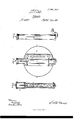
To enable others skilled in the art to make and use my new apparatus for measuring and testing liquids, I will proceed to describe the same in detail, in which- Figure l is an end elevation of a c ask or barrel having my apparatus applied thereto.
Figure 2 is a detached view of a modified form of the tubes, through which the'liqnid is seen, to determine its proof and the quantity contained in the vessel.
Figure 3 is a view of' the graduated gauge-,plate removed, showing its adjustability.
Figure 4 is a vertical longitudinal section of a cask or barrel, having-my apparatus applied thereto.
Figure 5 is an end view of a cask or barrel, showing the graduated gauge-plate iu position, and the tube extending above and below the barrel.
Figure 6 is a vertical section of the tube or pipe detached from tbe cask, and provided with a removable cap secured to its upper end.
Y Figure 7 is a side elevation of' the tube, also de` tached, showing the form of its connection with the cask.
A, in the annexed drawings, represents a cask or barrel, of the usual forni and construction, to which my gauge I for determining the quantity contained therein is applied; also, a hydrometer, c', in combination therewith, to test the proof or specific' gravity of the liquid.
Upon a plate, C, secured to the head of the cask A, containing the liquid to be measured and tested by this apparatus, is mounted a glass or transparent tube, B, and retained in position upon this plate C by straps e.
To the lower end of this tube B is fitted a cap, D, from which extends a stem, u, through the head E ot the eask A containing the liquid, connecting' the tube B with the interior ofthe Cask, so that the liquid `may nd its level in the tube B.
'lo the upper end of this transparent Vtube B isY This raduated aune may bevre'tained in position by the extended ends ot the straps e, or in anyother convenient manner, and is adjustable perpei'idicnlarly, so as to be adapted to the differently-formed casks or barrels to which itV may be applied, and is removable so as to be replaced by a difierently-graduated gauge,
if required.
To connect this transparent or glass tube B with the vessel containing the liquid to be measured and tested, so as to equalize the atmospheric pressure above the liquid in the tube and cask B," that the liquid may find its level, as shown iu tig. 4, the upper end maybe provided with a stem', F, (see dotted liues,) extending into the cask, similar to the stem u at the lower ond, or a small opening, c, through the cap H, to allow the air to escape, may be made.
If to gauge the quantity and test the proof of' liquids in diierent or separate tubesbe desired or` preferred, a bent tube, W, somewhat 1n the forni ot the letter U, may be employed, as. represented in iig. 2, the one arm, g, receiving the hydrometer c., and the other arm, m, simply exhibiting the quantity of 'liquid contained in the cask or barrel, and indicated* by the gauge-plate P.
Totest and gauge in casks which are ,somewhat larger at 'the middle than the ends, the `tube B may extend both above and below the upper and lower sides, as shown in iig. 5, iu which case a bent connection, O, may be used, as shown in iig. 7. Fig'. 6 represents the tube B the length. of the di- 4anieter of the barrel-head only, and in order to provide for the stein -r of the liydi'ometer when the Cask is full, o'r nearly so, a removable cap, M, may be provided, which can be dispensed with when transport-ing .the cask, if necessary. g
It is obvious that many different lornis may be usedto cieet the purpose of measuring the quantity f and indicating the proof of liquids by` one apparatus without depart-ing from my invention, but the varions ways or modifications exhibited' here are deemed suicient to fully illustrate and protect my invention.
.Cases may be employed to inclose this apparatus to prevent accident, but a representation of which is not deemed necessary in this application for a patent, and is therefore omitted.
Having thus fully described my apparatus for measurin, r or gauging and testing the proof of liquids,
What I claim as my invention, and desireto secure byLetters Patent, is- I 1. The combination of a transparent gauge, B, attached to a cask or vessel, E, for indicating the liquid contents thereof, with a hydrolneter, c', for indicating the strength or specic gravity of the liquid: substantially as herein specified.
2. In combination with the foregoing, also the al? rangement of an adjustable and removable scale, P, as set forth. l
S. R. P. CAMP.-
Witnesses:
S. W. Woon, THEO. HUMBERT.
Publications (1)
| Publication Number | Publication Date |
|---|---|
| US103976A true US103976A (en) | 1870-06-07 |
Family
ID=2173461
Family Applications (1)
| Application Number | Title | Priority Date | Filing Date |
|---|---|---|---|
| US103976D Expired - Lifetime US103976A (en) | Improvement in combined liquid gauge and hydrometer |
Country Status (1)
| Country | Link |
|---|---|
| US (1) | US103976A (en) |
-
0
- US US103976D patent/US103976A/en not_active Expired - Lifetime
Similar Documents
| Publication | Publication Date | Title |
|---|---|---|
| US398528A (en) | Measuring apparatus for liquids | |
| US103976A (en) | Improvement in combined liquid gauge and hydrometer | |
| US1156998A (en) | Measuring instrument. | |
| US1277760A (en) | Field-standard for testing liquid-measuring devices. | |
| US1125236A (en) | Strain-indicator. | |
| US801202A (en) | Multiplying draft-gage. | |
| US1399394A (en) | Glass chemical ware | |
| US124389A (en) | Improvement in leveling instruments | |
| US980320A (en) | Liquid-gage. | |
| US616594A (en) | Self-measuring milk-can | |
| US1012993A (en) | Clinometer. | |
| US977216A (en) | Cask-faucet gage. | |
| US3884067A (en) | Tensiometer | |
| US111885A (en) | Giuseppe tagliabue | |
| US287342A (en) | Level | |
| US51879A (en) | Improvement in thiefs and tests for liquids | |
| US1039923A (en) | Fluid-gage. | |
| US813977A (en) | Titration apparatus. | |
| US60806A (en) | Joseph tkent | |
| US823932A (en) | Device for measuring liquids. | |
| US397695A (en) | Leveling-instrument | |
| US590501A (en) | Xxhixotoh | |
| US599704A (en) | George j | |
| US266460A (en) | Indicator for spirit-cisterns | |
| US110202A (en) | Improvement in liquor-thieves and measures |