US10389976B2 - Information processing apparatus, information processing system, and information processing method - Google Patents
Information processing apparatus, information processing system, and information processing method Download PDFInfo
- Publication number
- US10389976B2 US10389976B2 US16/073,519 US201716073519A US10389976B2 US 10389976 B2 US10389976 B2 US 10389976B2 US 201716073519 A US201716073519 A US 201716073519A US 10389976 B2 US10389976 B2 US 10389976B2
- Authority
- US
- United States
- Prior art keywords
- user
- image
- dialog pair
- display
- dialog
- Prior art date
- Legal status (The legal status is an assumption and is not a legal conclusion. Google has not performed a legal analysis and makes no representation as to the accuracy of the status listed.)
- Expired - Fee Related
Links
Images


Classifications
-
- H—ELECTRICITY
- H04—ELECTRIC COMMUNICATION TECHNIQUE
- H04N—PICTORIAL COMMUNICATION, e.g. TELEVISION
- H04N7/00—Television systems
- H04N7/14—Systems for two-way working
- H04N7/15—Conference systems
-
- H—ELECTRICITY
- H04—ELECTRIC COMMUNICATION TECHNIQUE
- H04N—PICTORIAL COMMUNICATION, e.g. TELEVISION
- H04N7/00—Television systems
- H04N7/14—Systems for two-way working
-
- H—ELECTRICITY
- H04—ELECTRIC COMMUNICATION TECHNIQUE
- H04N—PICTORIAL COMMUNICATION, e.g. TELEVISION
- H04N7/00—Television systems
- H04N7/14—Systems for two-way working
- H04N7/141—Systems for two-way working between two video terminals, e.g. videophone
- H04N7/147—Communication arrangements, e.g. identifying the communication as a video-communication, intermediate storage of the signals
-
- H—ELECTRICITY
- H04—ELECTRIC COMMUNICATION TECHNIQUE
- H04N—PICTORIAL COMMUNICATION, e.g. TELEVISION
- H04N5/00—Details of television systems
- H04N5/222—Studio circuitry; Studio devices; Studio equipment
- H04N5/262—Studio circuits, e.g. for mixing, switching-over, change of character of image, other special effects ; Cameras specially adapted for the electronic generation of special effects
- H04N5/272—Means for inserting a foreground image in a background image, i.e. inlay, outlay
Definitions
- the present disclosure relates to an information processing apparatus, an information processing system, an information processing method, and a program. More specifically, for example, the present invention relates to an information processing apparatus, an information processing system, an information processing method, and a program that transmit images and voices by bidirectional telecommunication via a network so as to execute bidirectional communication.
- An bidirectional communication system such as a video conference system that transmits and receives images and voices through bidirectional telecommunication via a network is used in various fields.
- This bidirectional communication system includes a problem that a line-of-sight direction of a user such as a conference participant displayed on a display unit (display) does not match the direction in which the user actually gazes.
- This problem can be serious particularly in a case where a plurality of users (for example, conference participant) is present in front of the display unit.
- the user at the position corresponding to the position of the camera that photographed the display image on the display unit can observe the image without feeling strange.
- the user existing at a position different from the position corresponding to the position of the camera that photographed the display image on the display unit, the line-of-sight of the other user (conference participant) displayed on the display unit might look completely different from the original situation.
- a viewing user viewing this display image might be puzzled about to whom the displayed user is speaking to.
- Patent Document 1 Japanese Patent No. 3139100
- Patent Document 2 Japanese Patent No. 32389730
- Patent Document 3 Japanese Patent Application Laid-Open No. 2012-070081
- Patent Document 4 Japanese Patent Application Laid-Open No. 2014-096701
- Patent Document 5 Japanese Patent Application Laid-Open No. 2012-088538
- the methods disclosed in these conventional technologies include a configuration that requires the number of cameras corresponding to the number of participants, a configuration that requires use of a special display, a configuration that requires special image processing of correcting an eye image of a face included in the image to change the line-of-sight direction, or the like, leading to a problem of cost increase and complication of the processing.
- Patent Document 1 Japanese Patent No. 3139100
- Patent Document 2 Japanese Patent No. 32389730
- Patent Document 3 Japanese Patent Application Laid-Open No. 2012-070081
- Patent Document 4 Japanese Patent Application Laid-Open No. 2014-096701
- Patent Document 5 Japanese Patent Application Laid-Open No. 2012-088538
- the present disclosure has been made in view of the above-described problems, for example, and aims to provide an information processing apparatus, imaging apparatus, information processing system, an information processing method, and a program capable of easy discrimination of to whom among the viewing users viewing the display unit, the communication participating user (displayed user) displayed in a display image of a display unit (display) used in a bidirectional communication system is speaking to, for example.
- a first aspect of the present disclosure is
- an information processing apparatus including a display image generation unit that generates dialog pair identification information enabling identification of to which viewing user among a plurality of viewing users a displayed user on a display unit is speaking, and that outputs the generated dialog pair identification information together with the displayed user, to the display unit.
- an information processing apparatus including a dialog pair determination unit that determines to which viewing user among a plurality of viewing users a displayed user on a display unit is speaking,
- dialog pair determination information indicating a pair of a displayed user and a viewing user forming a dialog pair by analyzing each of the images.
- an information processing system including: a transmission apparatus that executes image transmission; and a reception apparatus that receives a transmission image from the transmission apparatus and displays the transmission image on a display unit,
- the transmission apparatus transmits:
- dialog pair determination information indicating which displayed user is speaking to which viewing user among a plurality of viewing users viewing the display unit
- dialog pair identification information enabling identification of which displayed user is speaking to which viewing user on the basis of the dialog pair determination information, and outputs the generated information together with the displayed user, to the display unit.
- the information processing apparatus includes a display image generation unit that generates a display image for a display unit, and
- the display image generation unit generates
- dialog pair identification information enabling identification of to which viewing user among a plurality of viewing users a displayed user on the display unit is speaking, and outputs the generated information together with the displayed user, to the display unit.
- the information processing apparatus includes a display image generation unit that generates a display image for a display unit, and
- the program causes the display image generation unit to execute processing of generating dialog pair identification information enabling identification of to which viewing user among a plurality of viewing users the displayed user on the display unit is speaking, and processing of outputting the generated information together with the displayed user, to the display unit.
- the program of the present disclosure is a program that can be provided by a storage medium or a telecommunication medium provided in a computer readable format to an information processing apparatus or a computer system that can execute various program codes, for example.
- processing according to the program is implemented on the information processing apparatus or the computer system.
- system represents a logical set of a plurality of apparatuses, and that all the constituent apparatuses need not be in a same housing.
- the configuration includes a display image generation unit that generates dialog pair identification information enabling identification of to which viewing user among the plurality of viewing users the displayed user on the display unit is speaking, and outputs the generated information together with the displayed user, to the display unit.
- the display image generation unit generates, as the dialog pair identification information, an arrow or an icon, a face surrounding frame or a face side line, a virtual viewpoint background image or the like, directed from the displayed user forming the dialog pair to the viewing user forming the dialog pair, and displays the generated dialog pair identification information together with the displayed user, on the display unit.
- FIG. 1 is a diagram illustrating a bidirectional communication system.
- FIGS. 2A, 2B, and 2C are diagrams illustrating a bidirectional communication system.
- FIGS. 3A and 3B are diagrams illustrating problems of an image displayed on a display unit.
- FIGS. 4A and 4B are diagrams illustrating problems of an image displayed on a display unit.
- FIGS. 5A and 5B are diagrams illustrating an exemplary solution of a problem of an image displayed on a display unit.
- FIG. 6 is a diagram illustrating an exemplary solution of a problem of an image displayed on a display unit.
- FIG. 7 is a diagram illustrating exemplary processing executed by an information processing apparatus according to a first exemplary embodiment of the present disclosure.
- FIG. 8 is a diagram illustrating exemplary processing executed by an information processing apparatus according to the first exemplary embodiment of the present disclosure.
- FIG. 9 is a diagram illustrating exemplary processing executed by an information processing apparatus according to the first exemplary embodiment of the present disclosure.
- FIG. 10 is a diagram illustrating exemplary processing executed by an information processing apparatus according to the first exemplary embodiment of the present disclosure.
- FIG. 11 is a diagram illustrating an exemplary configuration of an information processing apparatus according to the first exemplary embodiment of the present disclosure.
- FIG. 12 is a flowchart illustrating a processing sequence executed by the information processing apparatus of the present disclosure.
- FIG. 13 is a flowchart illustrating a processing sequence executed by the information processing apparatus of the present disclosure.
- FIG. 14 is a diagram illustrating an exemplary configuration of an information processing apparatus according to a second exemplary embodiment of the present disclosure.
- FIG. 15 is a diagram illustrating an exemplary configuration of an information processing apparatus according to a third exemplary embodiment of the present disclosure.
- FIG. 16 is a diagram illustrating an exemplary configuration of an information processing apparatus according to a fourth exemplary embodiment of the present disclosure.
- FIG. 17 is a diagram illustrating an exemplary configuration of a display image generation unit of an information processing apparatus according to a fourth exemplary embodiment of the present disclosure.
- FIGS. 18A, 18B, and 18C are diagrams illustrating exemplary processing executed by the information processing apparatus according to the fourth exemplary embodiment of the present disclosure.
- FIG. 19 is a diagram illustrating an exemplary configuration of an information processing apparatus according to a fifth exemplary embodiment of the present disclosure.
- FIG. 20 is a diagram illustrating an exemplary configuration of a display image generation unit of the information processing apparatus according to the fifth exemplary embodiment of the present disclosure.
- FIGS. 21A and 21B are diagrams illustrating an example of using a face surrounding frame as dialog pair identification information.
- FIG. 22 is a flowchart illustrating a processing sequence of the information processing apparatus in a case where a face surrounding frame is used as the dialog pair identification information.
- FIGS. 23A, 23B, and 23C are diagrams illustrating a specific example of processing of an information processing apparatus in a case where a face surrounding frame is used as the dialog pair identification information.
- FIGS. 24A and 24B are diagrams illustrating an example of using a face side line as the dialog pair identification information.
- FIG. 25 is a flowchart illustrating a processing sequence of the information processing apparatus in a case where a face side line is used as the dialog pair identification information.
- FIGS. 26A, 26B, and 26C are diagrams illustrating a specific example of processing of an information processing apparatus in a case where a face side line is used as the dialog pair identification information.
- FIGS. 27A and 27B are diagrams illustrating an example of using a face side box as the dialog pair identification information.
- FIGS. 28A and 28B are diagrams illustrating an example of using a face side sphere as the dialog pair identification information.
- FIG. 29 is a flowchart illustrating a processing sequence of an information processing apparatus in a case where a face side box (or sphere) is used as the dialog pair identification information.
- FIGS. 30A, 30B, and 30C are diagrams illustrating a specific example of processing of an information processing apparatus in a case where a face side box (or sphere) is used as the dialog pair identification information.
- FIGS. 31A and 31B are diagrams illustrating an example of using a background perspective transformation as the dialog pair identification information.
- FIG. 32 is a flowchart illustrating a processing sequence of the information processing apparatus in a case where a background perspective transformation is used as the dialog pair identification information.
- FIGS. 33A, 33B, and 33C are diagrams illustrating a specific example of processing of an information processing apparatus in a case where a background perspective transformation is used as the dialog pair identification information.
- FIG. 34 is a diagram illustrating a specific example of processing of an information processing apparatus in a case where a background perspective transformation is used as the dialog pair identification information.
- FIG. 35 is a diagram illustrating a specific example of processing of an information processing apparatus in a case where a background perspective transformation is used as the dialog pair identification information.
- FIGS. 36A and 36B are diagrams illustrating a specific example of processing of an information processing apparatus in a case where a background perspective transformation is used as the dialog pair identification information.
- FIG. 37 is a diagram illustrating a specific example of processing of an information processing apparatus in a case where a background perspective transformation is used as the dialog pair identification information.
- FIGS. 38A and 38B are diagrams illustrating an example in which face shading correction of a face is used as dialog pair identification information.
- FIG. 39 is a flowchart illustrating a processing sequence of the information processing apparatus in a case where a face shading correction is used as the dialog pair identification information.
- FIGS. 40A, 40B, 40C, 40D, and 40E are diagrams illustrating a specific example of processing of an information processing apparatus in a case where face shading correction is used as the dialog pair identification information.
- FIG. 41 is a diagram illustrating a specific example of processing of an information processing apparatus in a case where face shading correction is used as the dialog pair identification information.
- FIG. 42 is a diagram illustrating a specific example of processing of an information processing apparatus in a case where face shading correction is used as the dialog pair identification information.
- FIG. 43 is a diagram illustrating an exemplary configuration of hardware of an information processing apparatus.
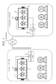
- FIG. 1 is a diagram illustrating an exemplary configuration of a bidirectional communication system.
- FIG. 1 includes:
- FIG. 1 illustrates a configuration example of these two locations.
- These two locations are provided at remote places separated from each other, and users at individual locations perform bidirectional communication with each other. Individual systems at individual locations are connected with each other via a network 30 .
- the first location includes users A, B, and C.
- the first location includes a data processing unit 10 , together with a display unit (display) 11 , a camera 12 , and a voice input/output unit (microphone and speaker) 13 , connected to the data processing unit 10 .
- a display unit display
- a camera camera
- a voice input/output unit microphone and speaker
- the second location includes users D, E and F.
- the second location includes a data processing unit 20 , together with a display unit (display) 21 , a camera 22 , and a voice input/output unit (microphone and speaker) 23 , connected to the data processing unit 20 .
- a display unit display
- a camera 22 camera
- a voice input/output unit microphone and speaker
- the camera 12 at the first location photographs the users A, B, and C at the first location, and photographed image data is transmitted to the data processing unit 20 at the second location via the data processing unit 10 and the network 30 .
- the data processing unit 20 at the second location displays a received image from the first location, on the display unit 21 .
- the voice input/output unit (microphone and speaker) 13 at the first location obtains speech or the like of the users A, B, and C at the first location, and the obtained voice data is transmitted to the data processing unit 20 at the second location via the data processing unit 10 and the network 30 .
- the data processing unit 20 at the second location outputs the received voice from the first location via the voice input/output unit (microphone and speaker) 23 .
- the camera 22 at the second location photographs the users D, E, and F at the second location, and photographed image data is transmitted to the data processing unit 10 at the first location via the data processing unit 20 and the network 30 .
- the data processing unit 10 at the first location displays the image received from the second location, on the display unit 11 .
- the voice input/output unit (microphone and speaker) 23 at the second location obtains speech or the like of the users D, E, and F at the second location, and the obtained voice data is transmitted to the data processing unit 10 at the first location via the data processing unit 20 and the network 30 .
- the data processing unit 10 at the first location outputs the received voice from the second location via the voice input/output unit (microphone and speaker) 13 .
- This processing enables the users A, B, and C at the first location and the users D, E, and F at the second location to obtain images and speech of remote users via the display unit and the speaker, so as to perform bidirectional communication.
- FIGS. 2A, 2B, and 2C are diagrams illustrating one example of a communication environment implemented in a bidirectional communication system.
- FIG. 2A illustrates users A, B, and C on the first location side and users D, E, and F at the second location displayed on the display unit 11 .
- FIG. 2B illustrates users D, E, and F on the second location side and users A, B, and C at the first location displayed on the display unit 21 .
- This bidirectional communication system includes a problem that a line-of-sight direction of a user displayed on the display unit (display) does not match the direction in which the user actually gazes.
- This problem can be serious particularly in a case where a plurality of users (for example, conference participant) is present in front of the display unit.
- FIGS. 3A and 3B are diagrams illustrating an exemplary display image displayed on the display unit of each of locations in the bidirectional communication system described with reference to FIGS. 1 and 2 .
- the display unit 11 of the first location displays images of users D, E, and F at the second location.
- This image is an image photographed by the camera 22 at the second location.
- the images of the users A, B, and C at the first location are displayed on the display unit 21 at the second location.
- This image is an image photographed by the camera 12 at the first location.
- the user C speaks, with eye-gaze, to the center direction (P 2 ) of the display unit 11 .
- FIGS. 3A and 3B include identifiers P 1 , P 2 , and P 3 from the left side of the figure as position identifiers indicating the horizontal direction of the display unit 11 .
- the camera 12 for photographing the users A, B, and C at the first location is fixed in the central region (P 2 ) in the horizontal direction of the display unit.
- the camera 12 photographs the viewpoint image from the position P 2 and the photographed image is displayed on the display unit 21 at the second location.
- the users A, B, and C at the first location displayed on the display unit 21 at the second location are set as illustrated in FIGS. 3A and 3B .
- the speaking user C at the first location is speaking, with eye-gaze, to the user E displayed on the display unit 11 .
- This line-of-sight is directed to the position (P) of the camera 12 .
- the user C is in a state of speaking with the line-of-sight directed to the camera 12 , and the image of the user C is photographed as a front-facing image with respect to the camera 12 .
- the image of the first location C displayed on the display unit 21 of the second location is an image facing the front.
- the display image of the display unit 21 at the second location is a display image in which the user C seems to be speaking to the user F at the second location.
- the line-of-sight direction of the subject displayed on the display unit is decided by the position of the photographing viewpoint of the camera, leading to observation of an image in a line-of-sight direction different from the actual line-of-sight direction depending on the position of the user arranged in a line in front of the display unit.
- FIGS. 4A and 4B are diagrams illustrating another example in which an image with an erroneous line-of-sight direction is displayed.
- the display unit 11 of the first location displays images of users D, E, and F at the second location.
- This image is an image photographed by the camera 22 at the second location.
- the images of the users A, B, and C at the first location are displayed on the display unit 21 at the second location.
- This image is an image photographed by the camera 12 at the first location.
- FIGS. 4A and 4B is an are examples in which the user C at the first location is speaking, with eye-gaze, to the user F at the second location displayed on the display unit 11 .
- the users D, E, and F at the second location are displayed on the display unit 11 . Since the user F is displayed in a front region (P 3 ) from the user C on the display unit 11 , the user C speaks, with eye-gaze, to a front (P 3 ) of the display unit 11 .
- the camera 12 for photographing the users A, B, and C at the first location is fixed in the central region (P 2 ) in the horizontal direction of the display unit.
- the camera 12 photographs the viewpoint image from the position P 2 and the photographed image is displayed on the display unit 21 at the second location.
- the users A, B, and C at the first location displayed on the display unit 21 at the second location are set as illustrated in FIGS. 3A and 3B .
- the speaking user C at the first location is speaking, with eye-gaze, to the user F displayed on the display unit 11 .
- This line-of-sight is not directed to the position (P) of the camera 12 .
- the user C is in a state of speaking with the line-of-sight directed to a direction different from the camera 12 , and the image of the user C is photographed as an image with the line-of-sight directed to a direction different from the camera 12 .
- the image of the first location C displayed on the display unit 21 of the second location is an image facing rightward (outer side than F), as illustrated in the drawing.
- the display image of the display unit 21 at the second location is a display image in which the user C seems to be speaking to outer side than the user F at the second location.
- the line-of-sight direction of the subject displayed on the display unit is decided depending on the position of the photographing viewpoint of the camera.
- This line-of-sight direction is the line-of-sight direction viewed from the camera viewpoint.
- the viewing user in front of the display unit displaying the photographed image observes the display image from the viewpoint position different from the viewpoint of the camera that photographed the image, the line-of-sight direction of the person in the display image is different from the actual line-of-sight direction, leading to hindrance of smooth communication.
- Patent Document 2 Japanese Patent No. 3289730 discloses a configuration, as illustrated in FIGS. 5A and 5B , in which images of various viewpoint directions are captured by a plurality of cameras 31 to 33 , and the plurality of images is displayed on a multi-viewpoint image display 35 .
- the multi-viewpoint image display 35 is a special display that enables viewing of images that differ depending on the viewing direction.
- a photographed image of a D viewpoint image photographing camera 31 displayed on the multi-viewpoint image display 35 can be viewed solely from the position of the user D at the second location.
- a photographed image of a E viewpoint image photographing camera 31 displayed on the multi-viewpoint image display 35 can be viewed solely from the position of the user E at the second location.
- a photographed image of a viewpoint F image photographing camera 31 displayed on the multi-viewpoint image display 35 can be viewed solely from the position of the user F at the second location.
- the users D, E, and F at the second location can view images giving no strange feeling corresponding to their individual positions (viewpoints).
- Patent Document 3 Japanese Unexamined Patent Application Publication No. 2012-070081 discloses a configuration that corrects and displays the position, the shape, or the like of the eyes on the face of a person included in the display image so as to allow the display image on the display unit to match with the actual line-of-sight direction.
- This processing need to extract a face image to be displayed on the display unit, identify the image region of the eye included in the extracted face image, and perform correction processing on the eye image region in accordance with the actual line-of-sight direction of each of persons, leading to necessity of performing special image processing.
- the following is description of a configuration of the present disclosure enabling clear discrimination of to whom among the viewing users viewing the display unit the communication participating user (displayed user) displayed on the display unit (display) is speaking to without causing such a problem.
- the information processing apparatus controls a display image on a display unit (display) used in the bidirectional communication system illustrated in FIGS. 1 and 2 described above, for example.
- FIG. 7 is a diagram illustrating a state of a first location as one of the locations during execution of the bidirectional communication described with reference to FIGS. 1 and 2 .
- the illustration includes viewing users A to C, 130 as users of the first location, and a display unit 101 .
- the display unit 101 includes a camera 102 and a speaker 103 .
- the display unit 101 displays users D to F at the second location.
- the user displayed on the display unit is referred to as a “displayed user”, and the user viewing the display unit is referred to as a “viewing user”.
- the displayed users 110 illustrated in FIG. 7 are users D, E, and F, and the viewing users 130 are users A, B, and C.
- “dialog pair identification information 121 ” indicating to which viewing user the displayed user (speaker) displayed on the display unit 101 is speaking is displayed on the display unit 101 .
- the arrow illustrated above the displayed user E of the display unit 101 in the figure is the “dialog pair identification information 121 ”.
- the pair of users having dialog that is, “dialog pair” is the displayed user E and the viewing user C. That is, the dialog pair is “E-C”.
- the “arrow” being the “dialog pair identification information 121 ” displayed on the display unit 101 in the figure is illustrated in the vicinity of the displayed user E (upper portion in the present example) forming the dialog pair, and the direction of the arrow is displayed as a setting arrow directed toward the viewing user C of the dialog pair.
- the viewing users A to C can correctly judge that the displayed user E is speaking to the viewer user C.
- the viewing user C can immediately confirm that the displayed user E is speaking to oneself, and smooth communication is achieved.
- FIG. 8 illustrates an exemplary case where the “dialog pair” is the displayed user F and the viewing user A. That is, the dialog pair is “F-A”.
- the “arrow” being the “dialog pair identification information 122 ” displayed on the display unit 101 in the figure is illustrated in the vicinity of the displayed user F (upper portion in the present example) forming the dialog pair, and the direction of the arrow is displayed as a setting arrow directed toward the viewing user A of the dialog pair.
- the viewing users A to C correctly judge that the displayed user F is speaking to the viewing user A.
- the viewing user A can immediately confirm that the displayed user F is speaking to oneself, and smooth communication is achieved.
- FIGS. 7 and 8 are examples using identification marks shaped like an “arrow” as the “dialog pair identification information”.
- dialog pair identification information is not limited to this arrow, but various forms are possible.
- FIG. 9 illustrates an example of using “dialog pair identification information 123 ” that arranges human-shaped icons similar to the arrangement of the viewing users.
- the “viewing user line icon” as the “dialog pair identification information 123 ” displayed on the display unit 101 of FIG. 9 is indicated in the vicinity (upper portion in the present example) of the displayed user E forming the dialog pair.
- one user icon corresponding to the position of the viewing user C forming the dialog pair blinks.
- the viewing users A to C can correctly judge that the displayed user E is speaking to the viewing user C.
- the viewing user C can immediately confirm that the displayed user E is speaking to oneself, and smooth communication is achieved.
- FIG. 10 illustrates an example in a case where the dialog pair is F-A.
- the “viewing user line icon” as the “dialog pair identification information 124 ” displayed on the display unit 101 of FIG. 10 is indicated in the vicinity (upper portion in the present example) of the displayed user F forming the dialog pair.
- one user icon corresponding to the position of the viewing user A forming the dialog pair blinks.
- the viewing user A can immediately confirm that the displayed user F is speaking to oneself, and smooth communication is achieved.
- FIG. 11 illustrates a configuration example of an information processing apparatus of a first location and a second location, executing bidirectional communication via a network.
- Apparatuses at individual locations perform telecommunication via a network 170 such as the Internet, and users at the individual locations perform bidirectional communication such as a conference.
- the “dialog pair identification information” described with reference to FIGS. 7 to 10 is superimposed and displayed on the displayed user in the display unit of the second location illustrated in FIG. 11 , that is, a second location display unit 165 indicated at the lower right end of FIG. 11 .
- the “dialog pair identification information” is not displayed on the display unit of the first location illustrated in FIG. 11 , that is, the first location display unit 155 indicated at the upper left end of FIG. 11 , and a normal image including the displayed user alone is displayed.
- the first location imaging unit (camera) 151 photographs a user at the first location, for example, users A to C.
- a first location photographed image s, 172 s , as the photographed image, is transmitted from the first location transmission/reception unit 154 to the second location via the network 170 .
- voice data is also transmitted together with the image.
- Data transmitted and received between locations are discriminated such that (s) is added to the transmission side data and (r) is added to the reception side data.
- the first location photographed image s, 172 s which is the photographed image described above is image data transmitted from the first location to the second location, and (s) is added.
- a first location photographed image r, 172 r illustrated on the second location side in FIG. 11 is the same data as the “first location photographed image s, 172 s ” illustrated on the first location side. This is the data transmitted from the first location to the second location and received by the information processing apparatus at the second location, illustrated with (r) added.
- the first location display unit 155 displays the second location photographed image r, 181 r transmitted from the second location.
- the first location user information acquisition unit 152 includes a microphone for acquisition of user information other than the image data obtained by the first location imaging unit (camera) 151 , for example, voice data and a voice direction, a sensor for acquisition of the user position or a distance from the camera, or the like.
- the user information together with the user image information photographed by the imaging unit 151 is input to the dialog pair determination unit 153 .
- the first location photographed image s, 172 s and the first location user information 171 are input to the dialog pair determination unit 153 .
- the dialog pair determination unit 153 inputs, also from the second location, the second location photographed image r, 181 r which is an image of the user on the second location side, and second location user information 182 r including the voice and the position information of the user at the second location and the like.
- the dialog pair determination unit 153 uses the input data to examine which pair of users among the first location side users and the second location side users are executing the dialog, namely execute dialog pair detection processing.
- the processing identifies the users executing a dialog between the first location and the second location, so as to obtain the position information of these users.
- the presence or absence of a dialog is first determined on the basis of voice data, and in a case where it is determined that a dialog is present, the users at individual locations executing the dialog is identified from the image data, the voice direction data, or the like.
- This identification processing can be performed, for example, by analysis based on voice direction data or by analysis of a line-of-sight direction of a dialog user using image data or the like.
- the user position information is position information needed for displaying the dialog pair identification information described above with reference to FIGS. 7 to 10 , and includes the display position of the displayed user forming the dialog pair and the relative position of the viewing user in front of the display unit with respect to the display unit.
- the dialog pair determination unit 153 identifies the dialog pair using the user image, the voice, the voice direction information, the user position information, or the like obtained from each of locations, determines the position of the user forming the dialog pair, and generates dialog pair first determination information s, 173 s including these pieces of information.
- the dialogue pair first determination information s, 173 s generated by the dialog pair determination unit 153 is transmitted to the information processing apparatus at the second location via the first location transmission/reception unit 154 and the network 170 .
- dialog pair determination unit 153 generates the dialog pair determination information using the voice information and the sensor detection information other than the photographed image, it is also allowable to configure to generate the dialog pair determination information using the photographed image input from each of locations alone.
- the user position is discriminated from the camera position and the positional relationship of each of the users included in the image, and the mouth movement obtained from the image is analyzed to identify the speaker executing the dialog. With this processing, it is also possible to generate dialog pair determination information by using images alone.
- a second location imaging unit (camera) 161 photographs users at the second location, for example, the users D to F.
- a second location photographed image s, 181 s as the photographed image is transmitted from a second location transmission/reception unit 163 to the first location via the network 170 .
- voice data is also transmitted together with the image.
- the second location user information acquisition unit 162 includes a microphone for acquisition of user information other than the image data obtained by the second location imaging unit (camera) 161 , for example, voice data and a voice direction, a sensor for acquisition of the user position or a distance from the camera, or the like.
- Pieces of user information are transmitted to the first location together with the user image information photographed by the imaging unit 161 and input to the dialog pair determination unit 153 of the first location to be used for the dialog pair determination processing.
- the dialog pair first determination information generated by the dialog pair determination unit 153 at the first location is input to a second location display image generation unit 164 of the information processing apparatus at the second location.
- the first location photographed image r, 172 r , together with dialog pair first determination information r, 173 r generated by the dialog pair determination unit 153 at the first location are input to the second location display image generation unit 164 .
- the second location display image generation unit 164 applies these pieces of input data to generate a display image obtained by superimposing “dialog pair identification information” as described with reference to FIGS. 7 to 10 on the first location photographed image r, 172 r including the user of the first location, and outputs the generated display image to the second location display unit 165 .
- the second location display image generation unit 164 identifies the displayed user and the viewing user forming the dialog pair on the basis of the dialog pair first determination information r, 173 r generated by the dialog pair determination unit 153 of the first location, and further obtains position information of the users, and then, decides a display mode of “dialog pair identification information” to be displayed on the display unit on the basis of these pieces of information.
- the “dialog pair identification information” is displayed on the display image including the user at the first location in accordance with the display mode decided by this processing.
- the display image on which the “dialog pair identification information” as described above with reference to FIGS. 7 to 10 is superimposed is displayed on the second location display unit 165 .
- FIG. 11 is a case where the display image on which the “dialog pair identification information” is superimposed is displayed on the second location display unit 165 alone, it is also possible to allow the display image on which the “dialog pair identification information” is superimposed to be displayed on the first location display unit 155 by setting an image processing unit that executes image processing similarly to the processing executed by the second location display image generation unit 164 on the first location side.
- step S 101 the dialog pair determination 153 inputs the image and user information of the first location, and the image and user information of the second location.
- the dialog pair determination unit 153 inputs the first location photographed image s, 172 s which is an image of the user on the first location side, and the first location user information 171 including the voice, the position information, and the like of the user at the first location.
- the dialog pair determination unit 153 inputs the second location photographed image r, 181 r , which is the image of the user on the second location side received from the second location via the network, and the second location user information 182 r including the voice and the position information, and the like of the user at the second location.
- the dialog pair determination unit 153 determines in steps S 102 to S 103 whether there is a speaker in the first location side users and the second location side users, that is, whether a dialog is being executed by using data input in step S 101 .
- the processing includes determination of the presence or absence of the dialog on the basis of the voice data, for example.
- determination may be performed by detecting mouth movement from the image data.
- step S 104 the processing proceeds to step S 104 .
- step S 104 the dialog pair determination unit 153 determines the position and the line-of-sight direction of the dialog user (speaker).
- the line-of-sight direction analysis of the dialog user using the image data is executed.
- the dialog pair determination unit 153 determines in step S 105 a pair including the dialog user (speaker) and the user present in the line-of-sight direction of the speaker to be a dialog pair.
- the processing identifies the users executing a dialog between the first location and the second location.
- This identification processing can be performed, for example, by analysis based on voice direction data or by analysis of a line-of-sight direction of a dialog user using image data or the like.
- the user pair identified by this user identification processing is determined to be the dialog pair.
- dialog pair determination unit 153 generates in step S 105 dialog pair determination information including user identification information and user position information of the users forming the dialog pair.
- the user position information is position information needed for displaying the dialog pair identification information described above with reference to FIGS. 7 to 10 , and includes the display position of the displayed user forming the dialog pair and the relative position of the viewing user in front of the display unit with respect to the display unit.
- the dialog pair determination unit 153 identifies the dialog pair using the user image, the voice, the voice direction information, the user position information, or the like obtained from each of locations, determines the position of the user forming the dialog pair, and generates dialog pair determination information including these pieces of information.
- the dialog pair determination information generated by the dialog pair determination unit 153 is transmitted from the first location to the information processing apparatus at the second location so as to be used in generation processing of a display image including the dialog pair identification information described with reference to FIGS. 7 to 10 in the second location display image generation unit 164 of the information processing apparatus at the second location.
- the second location display image generation unit 164 inputs in step S 201 the photographed image of the displayed user and the dialog pair determination information.
- the first location photographed image r, 172 r , together with dialog pair first determination information r, 173 r generated by the dialog pair determination unit 153 at the first location are input to the second location display image generation unit 164 .
- the dialog pair determination information includes user identification information of a user of the dialog pair and user position information.
- the user position information is position information needed for displaying the dialog pair identification information described above with reference to FIGS. 7 to 10 , and includes the display position of the displayed user forming the dialog pair and the relative position of the viewing user in front of the display unit with respect to the display unit.
- the second location display image generation unit 164 obtains in step S 202 the positions of the displayed user and the viewing user executing the dialog from the dialog pair determination information input in step S 201 .
- step S 203 the second location display image generation unit 164 generates a display image obtained by superimposing dialog pair identification information indicating the positional relationship between the displayed user and the viewing user executing the dialog, on the photographed image of the displayed user, and outputs the generated image to the display unit.
- the second location display image generation unit 164 generates a display image obtained by superimposing “dialog pair identification information” as described with reference to FIGS. 7 to 10 on the first location photographed image r, 172 r including the user of the first location, and outputs the generated display image to the second location display unit 165 .
- the second location display image generation unit 164 identifies the displayed user and the viewing user forming the dialog pair on the basis of the dialog pair first determination information r, 173 r generated by the dialog pair determination unit 153 of the first location, and further obtains position information of the users, and then, decides a display mode of “dialog pair identification information” to be displayed on the display unit on the basis of these pieces of information.
- the “dialog pair identification information” is displayed on the display image including the user at the first location in accordance with the display mode decided by this processing.
- the display image on which the “dialog pair identification information” as described above with reference to FIGS. 7 to 10 is superimposed is displayed on the second location display unit 165 .
- the viewing user at the second location can immediately grasp correctly which user of the displayed users is speaking to which viewing user, leading to achievement of smooth communication.
- FIG. 14 is a diagram illustrating a configuration example of the information processing system according to the second exemplary embodiment.
- the dialog pair determination unit 211 is set in the information processing apparatus of the second location, and
- the first location display image generation unit 201 is set in the information processing apparatus of the first location.
- This configuration displays dialog pair identification information by superimposing the information on the displayed user image not merely in the second location display unit 165 but also in the first location display unit 155 .
- the dialog pair determination unit 211 of the information processing apparatus at the second location inputs the second location photographed images s, 181 s and the second location user information 182 s , and further inputs the first location photographed image r, 172 r as reception data from the first location, and the first location user information r, 171 r including voice, position information, and the like of the user of the first location.
- the dialog pair determination unit 211 uses the input data to examine which pair of users among the first location side users and the second location side users are executing the dialog, namely execute dialog pair detection processing.
- the processing identifies the users executing a dialog between the first location and the second location, so as to obtain the position information of these users.
- This processing is similar to the processing executed by the dialog pair determination unit 153 on the first location side described previously with reference to FIG. 11 .
- the dialog pair determination unit 211 identifies the dialog pair using the user image, the voice, the voice direction information, the user position information, or the like obtained from each of locations, determines the position of the user forming the dialog pair, and generates dialog pair second determination information s, 231 s including these pieces of information.
- the dialogue pair second determination information s, 231 s generated by the dialog pair determination unit 211 is transmitted to the information processing apparatus at the first location via the second location transmission/reception unit 163 and the network 170 .
- dialog pair determination unit 211 generates the dialog pair determination information using the voice information and the sensor detection information other than the photographed image, it is also allowable to configure to generate the dialog pair determination information using the photographed image input from each of locations alone.
- the user position is discriminated from the camera position and the positional relationship of each of the users included in the image, and the mouth movement obtained from the image is analyzed to identify the speaker executing the dialog. With this processing, it is also possible to generate dialog pair determination information by using images alone.
- the second location photographed image r, 181 r , together with dialog pair second determination information r, 231 r generated by the dialog pair determination unit 211 at the second location are input to the first location display image generation unit 201 at the first location.
- the first location display image generation unit 201 applies these pieces of input data to generate a display image obtained by superimposing “dialog pair identification information” as described with reference to FIGS. 7 to 10 on the second location photographed image r, 181 r including the user of the second location, and outputs the generated display image to the first location display unit 155 .
- the first location display image generation unit 201 identifies the displayed user and the viewing user forming the dialog pair on the basis of the dialog pair second determination information r, 231 r generated by the dialog pair determination unit 211 of the second location, and further obtains position information of the users, and then, decides a display mode of “dialog pair identification information” to be displayed on the display unit on the basis of these pieces of information.
- the “dialog pair identification information” is displayed on the display image including the user at the second location in accordance with the display mode decided by this processing.
- the display image on which the “dialog pair identification information” as described above with reference to FIGS. 7 to 10 is superimposed is displayed on the first location display unit 155 .
- the other processing is the similar to the case of the first exemplary embodiment, and thus the description is omitted.
- “dialog pair identification information” is superimposed on the display unit of both the first location and the second location in accordance with the user image of the other party's location and displayed.
- FIG. 15 is a diagram illustrating a configuration example of the information processing system according to the third exemplary embodiment.
- a front face generation unit 251 is set in the information processing apparatus of the first location.
- the front face generation unit 251 inputs photographed images from a plurality of different viewpoints from the first location imaging unit 151 and generates a 3D model of the user as a subject using the plurality of images.
- the 3D model includes three-dimensional position data of the subject and pixel value data of each of positions, and can be generated from images from different viewpoints.
- the front face generation unit 251 applies the generated 3D model to generate a front face image s, 252 s as a front-facing face image of the subject user, and transmits the generated image to the information processing apparatus at the second location via the network 170 .
- the second location display image generation unit 164 inputs the front face image r, 252 r , replaces the face region of the first location photographed image r, 172 r with this input front face image, and outputs the image.
- the “dialog pair identification information” is superimposed on the image replaced by the front-facing face image so as to be displayed on the second location display unit 165 .
- the displayed user's face displayed on the second location display unit 165 is displayed as an image facing the front, and furthermore, as a display image on which “dialog pair identification information” as described above with reference to FIGS. 7 to 10 is superimposed.
- the other processing is the similar to the case of the first exemplary embodiment, and thus the description is omitted.
- the user image of the other party's location displayed on the display unit is the front-facing face image. Accordingly, the viewing user can feel that the displayed user displayed on the display unit is speaking, with eye-gaze, to the viewing user side, making it possible to achieve smooth communication.
- the displayed user to whom the front-facing face image is to be applied may be all the displayed users or specified displayed user as a dialog pair.
- FIG. 16 is a diagram illustrating a configuration example of the information processing system according to the fourth exemplary embodiment.
- the person image correction unit 260 and the background image correction unit 270 are set in the second location display image generation unit 164 of the second location.
- FIG. 17 illustrates a specific configuration example of the second location display image generation unit 164 at the second location.
- a person/background image separation unit 255 of the second location display image generation unit 164 executes processing of separating a person image region included in the first location photographed image r, 172 r from a background image region.
- first location photographed image subject distance information (depth data) 255 r input from the first location is applied to this processing, for example.
- the information processing apparatus at the first location measures the subject distance using a depth sensor and transmits the measurement information to the second location.
- the person/background image separation unit 255 may execute processing of separating the person image region from the background image region on the basis of the plurality of images.
- the person image generated by the separation processing of the person/background image separation unit 255 is input to the front face image generation unit 261 of the person image correction unit 260 , while the background image is input to a viewpoint transformation image generation unit 271 of a background image correction unit 270 .
- the dialog pair first determination information r, 173 r and the first location photographed image subject distance information (depth data) 255 r are also input to the person image correction unit 260 and the background image correction unit 270 .
- the front face image generation unit 261 of the person image correction unit 260 generates a front face of the displayed user similarly to the case of the front face generation unit 251 in the third exemplary embodiment described above.
- the displayed user to whom the front-facing face image is to be applied may be all the displayed users or specified displayed user as a dialog pair.
- the viewpoint transformation image generation unit 271 of the background image correction unit 270 executes processing of changing the viewpoint and the perspective of the background image.
- the term “perspective” means a perspective view.
- An image displayed on the display unit is displayed as an image substantially corresponding to a perspective view from the viewpoint of the camera that has photographed the image. While there is no problem in a case where the camera viewpoint matches the viewpoint of the viewing user, the viewer would feel strange about the display image in a case where the camera viewpoint is different from the viewer's viewpoint.
- FIG. 18A illustrates a bidirectional communication execution environment.
- Viewing users (D, E, and F) 282 are exchanging dialogs with displayed users (A, B, and C) 283 displayed on the display unit 281 with a display unit 281 arranged on a table 280 .
- a camera 284 is installed at an upper center of the display unit.
- communication is executed with a display unit with a camera arranged on a table of a same shape also at the location on the displayed users A to C, 283 side.
- FIGS. 18B and 18C illustrate examples of perspectives (perspective views) as scenes observed from viewpoints of viewing users D, E, and F at this time.
- FIG. 18B is a perspective example (perspective views) as a scene observed by the viewing user E at the viewpoint position corresponding to the photographing camera (the camera installed at the location of the displayed users A to C) of the image displayed on the display unit 281 .
- FIG. 18C is an exemplary perspective (perspective view) as a scene observed by the viewing user F at a viewpoint position different from the camera photographing the image displayed on the display unit 281 .
- the inclination of the side surface line of an actual table substantially is aligned with the inclination of the side surface line of a table displayed on the display unit, enabling the viewing user E to observe the image without feeling strange.
- the inclination of the side surface line of an actual table substantially is not aligned with the inclination of the side surface line of a table displayed on the display unit, causing the viewing user F to observe the image with strange feelings.
- correcting the image observed by the viewing user F would make it possible to generate an image not strange to the viewing user F.
- processing that transforms an image displayed on the display unit to a virtual viewpoint image photographed from the viewpoint of the viewing user F is effective.
- the viewpoint transformation image generation unit 271 illustrated in FIG. 17 executes generation processing of this virtual viewpoint image.
- this processing generates a virtual viewpoint image (background image) observed from the viewpoint of the viewing user identified as a dialog pair.
- the first location photographed image subject distance information (depth data) 255 r input from the first location is applied to the generation of the virtual viewpoint image, for example.
- the information processing apparatus at the first location measures the subject distance using a depth sensor and transmits the measurement information to the second location.
- the viewpoint transformation image generation unit 271 may generate a virtual viewpoint image on the basis of the plurality of images.
- the viewpoint transformation image generation unit 271 generates a virtual viewpoint image (background image) observed from the viewpoint of the viewing user forming the dialog pair obtained from the dialog pair first determination information r, 173 r , and then outputs the generated image to an image combining unit 256 .
- the image combining unit 256 combines the front-facing person image generated by the front face image generation unit 261 with the virtual viewpoint image (background image) input from the viewpoint transformation image generation unit 271 , and further superimposes the dialog pair identification information to generate a combined image, and displays the combined image on the second location display unit 165 .
- the image displayed on the second location display unit 165 becomes a virtual viewpoint image observed from the viewpoint of the viewing user forming the dialog pair, and furthermore, the image being an image in which the displayed user forming the dialog pair faces the front.
- the viewing user can feel that the displayed user displayed on the display unit is speaking to the viewing user side, leading to achievement of smooth communication.
- the displayed user to whom the front-facing face image is to be applied may be all the displayed users or specified displayed user as a dialog pair.
- This exemplary embodiment is an exemplary embodiment based on the above-described fourth exemplary embodiment to which a configuration of sequentially updating a virtual viewpoint image to be generated with a background image in accordance with the movement of the viewing user forming a dialog pair is added.
- FIG. 19 is a diagram illustrating a configuration example of the information processing system of the fifth exemplary embodiment.
- a second location photographed image s, 181 s is input to the second location display image generation unit 164 at the second location.
- the configuration change (a) is applied to the configuration of FIG. 16 described in the fourth exemplary embodiment, and the virtual viewpoint image to be generated with the background image is sequentially updated in accordance with the movement of the viewing user forming the dialog pair.
- FIG. 20 illustrates a specific configuration example of the second location display image generation unit 164 at the second location.
- the difference from the configuration illustrated in FIG. 17 described in the fourth exemplary embodiment is that the second location photographed images s, 181 s are input to the background image correction unit 270 .
- the viewpoint transformation image generation unit 271 of the background image correction unit 270 generates a virtual viewpoint image (background image) observed from the viewpoint of the viewing user identified as a dialog pair similarly to the above-described fourth exemplary embodiment.
- the viewing user identified as a dialog pair move in front of the display unit or the camera.
- the viewpoint position of the viewing user is changed.
- the viewpoint transformation image generation unit 271 sequentially generates a virtual viewpoint image from the moving position of the viewing user in accordance with the moving position of the viewing user.
- the viewpoint transformation image generation unit 271 sequentially updates the virtual viewpoint image according to the position of the viewing user specified as the dialog pair, and displays the updated image on the display unit.
- the viewpoint transformation image generation unit 271 obtains from the second location photographed image s, 181 s the position information of the viewing user forming a dialog pair obtained from the dialog pair first determination information r, 173 r , and sequentially generates a virtual viewpoint image (background image) observed from this position (viewpoint) and outputs the generated images to the image combining unit 256 .
- the image combining unit 256 combines the front-facing person image generated by the front face image generation unit 261 with the virtual viewpoint image (background image) input from the viewpoint transformation image generation unit 271 , and further superimposes the dialog pair identification information to generate a combined image, and displays the combined image on the second location display unit 165 .
- the image displayed on the second location display unit 165 becomes a virtual viewpoint image observed from the viewpoint of the viewing user forming the dialog pair, and furthermore, the image being an image in which the displayed user forming the dialog pair faces the front.
- the present exemplary embodiment has a configuration in which the virtual viewpoint position of the background image is also changed together with the movement of the viewing user identified as a dialog pair, and this suppresses strangeness in the image observed even when the viewing user moves.
- the above-described exemplary embodiment includes description of specific examples of the dialog pair identification information, including the “arrow” described with reference to FIGS. 7 and 8 , and the “viewing user line icon” described with reference to FIGS. 9 and 10 , and furthermore, the “perspective transformation of background image” described with reference to FIG. 17 .
- dialog pair identification information Various types of display data can be used as the dialog pair identification information, besides these examples.
- dialog pair identification information will be described.
- FIGS. 21A and 21B illustrate a specific example in which the face surrounding frame is used as the dialog pair identification information.
- FIGS. 21A and 21B illustrate the following two examples.
- FIG. 21A Example 1 in which a dialog pair is represented by the shape of the face surrounding frame (case where the dialog pair is in the front direction of the displayed user on the screen)
- FIG. 21B Example 2 in which the dialog pair is represented by the shape of the face surrounding frame (case where the dialog pair is in the right direction of the displayed user on the screen)
- FIG. 21A is an exemplary case where the displayed user F and the viewing user C are a dialog pair.
- the viewing user C is present in front of the displayed user F.
- Dialog pair identification information 301 is a face surrounding frame set around the face of the displayed user F.
- FIG. 21B is an exemplary case where the displayed user F and the viewing user A are the dialog pair.
- the viewing user A is present in right direction of the displayed user F.
- Dialog pair identification information 302 is a face surrounding frame set around the face of the displayed user F.
- a face surrounding frame is set around the face of the displayed user as a member of the dialog pair, and the dialog pair can be identified by the shape of the set face surrounding frame.
- the processing following the flow illustrated in FIG. 22 is executed in the second location display image generation unit 164 illustrated in FIG. 11 or the like, or executed in the first location display image generation unit 201 illustrated in FIG. 14 or the like, for example.
- the second location display image generation unit 164 inputs in step S 311 the photographed image of the displayed user and the dialog pair determination information.
- the first location photographed image r, 172 r , together with dialog pair first determination information r, 173 r generated by the dialog pair determination unit 153 at the first location are input to the second location display image generation unit 164 .
- the dialog pair determination information includes user identification information of a user of the dialog pair and user position information.
- the user position information is position information needed for displaying the dialog pair identification information, and includes the display position of the displayed user forming the dialog pair and the relative position of the viewing user in front of the display unit with respect to the display unit.
- the second location display image generation unit 164 obtains in step S 312 the positions of the displayed user and the viewing user executing the dialog from the dialog pair determination information input in step S 311 .
- step S 313 the second location display image generation unit 164 decides an inclination angle ⁇ as a parameter defining the shape of the face surrounding frame.
- a dialog pair is formed with a dialog pair displayed user 305 and a dialog pair viewing user 306 .
- step S 313 the inclination angle ⁇ is calculated in accordance with the above formula.
- the second location display image generation unit 164 decides in step S 314 the setting (shape) of the face surrounding frame on the basis of a default vanishing point position and the inclination angle ⁇ .
- FIG. 23B illustrates an example of a face surrounding frame EFGH.
- FIG. 23C illustrates an exemplary generation procedure of the face surrounding frame EFGH.
- the shape decision processing of the face surrounding frame is executed in the following procedure.
- the center position of the face of the displayed user of the dialog pair is defined as C.
- Points vertically away from C by a predefined distance L 0 are defined as P and Q.
- (s4) Define EFGH surrounded by parallel lines passing through P and Q, and by lines OF and OG as the face surrounding frame EFGH.
- step S 314 the shape of the face surrounding frame is decided in accordance with the above processing.
- step S 315 the second location display image generation unit 164 generates a display image obtained by superimposing a face surrounding frame as the dialog pair identification information indicating the positional relationship between the displayed user and the viewing user executing the dialog, on the photographed image of the displayed user, and outputs the generated image to the display unit.
- a face surrounding frame is set around the face of the displayed user as a member of the dialog pair, whereby the dialog pair can be identified by the shape of the set face surrounding frame.
- the viewing user at the second location can immediately grasp correctly which user of the displayed users is speaking to which viewing user, leading to achievement of smooth communication.
- FIGS. 24A and 24B illustrate a specific example in which the face side line is used as the dialog pair identification information.
- FIGS. 24A and 24B illustrate the following two examples.
- FIG. 24A Example 1 in which a dialog pair is represented by the shape of the face side line (case where the dialog pair is in the front direction of the displayed user on the screen)
- FIG. 24B Example 2 in which a dialog pair is represented by the shape of the face side line (case where the dialog pair is in the right direction of the displayed user on the screen)
- FIG. 24A is an exemplary case where the displayed user F and the viewing user C are a dialog pair.
- the viewing user C is present in front of the displayed user F.
- Dialog pair identification information 311 is a face side line set around the face of the displayed user F.
- FIG. 24B is an exemplary case where the displayed user F and the viewing user A are the dialog pair.
- the viewing user A is present in right direction of the displayed user F.
- Dialog pair identification information 312 is a face side line set around the face of the displayed user F.
- a face side line is set around the face of the displayed user as a member of the dialog pair, and the dialog pair can be identified by the shape of the set face side line.
- the processing following the flow illustrated in FIG. 25 is executed in the second location display image generation unit 164 illustrated in FIG. 11 or the like, or executed in the first location display image generation unit 201 illustrated in FIG. 14 or the like, for example.
- the second location display image generation unit 164 inputs in step S 321 the photographed image of the displayed user and the dialog pair determination information.
- the first location photographed image r, 172 r , together with dialog pair first determination information r, 173 r generated by the dialog pair determination unit 153 at the first location are input to the second location display image generation unit 164 .
- the dialog pair determination information includes user identification information of a user of the dialog pair and user position information.
- the user position information is position information needed for displaying the dialog pair identification information, and includes the display position of the displayed user forming the dialog pair and the relative position of the viewing user in front of the display unit with respect to the display unit.
- the second location display image generation unit 164 obtains in step S 322 the positions of the displayed user and the viewing user executing the dialog from the dialog pair determination information input in step S 321 .
- step S 323 the second location display image generation unit 164 decides an inclination angle ⁇ as a parameter defining the shape of the face side line.
- a dialog pair is formed with a dialog pair displayed user 305 and a dialog pair viewing user 306 .
- step S 323 the inclination angle ⁇ is calculated in accordance with the above formula.
- the second location display image generation unit 164 decides in step S 324 the setting (shape) of the face side line on the basis of a default vanishing point position and the inclination angle ⁇ .
- FIG. 26B illustrates an example of face side lines EF and GH.
- FIG. 26C illustrates an example of generation procedure of the face side lines EF and GH.
- the face side line shape decision processing is executed in the following procedure.
- the center position of the face of the displayed user of the dialog pair is defined as C.
- Points vertically away from C by a predefined distance L 0 are defined as P and Q.
- step S 324 the shape of the face side line is decided in accordance with the above processing.
- step S 325 the second location display image generation unit 164 generates a display image obtained by superimposing a face side line as the dialog pair identification information indicating the positional relationship between the displayed user and the viewing user executing the dialog, on the photographed image of the displayed user, and outputs the generated image to the display unit.
- a face side line is set around the face of the displayed user as a member of the dialog pair, whereby the dialog pair can be identified by the shape of the set face side line.
- the viewing user at the second location can immediately grasp correctly which user of the displayed users is speaking to which viewing user, leading to achievement of smooth communication.
- FIGS. 27A, 27B, 28A, and 28B Specific examples using the face side box (or sphere) as the dialog pair identification information are illustrated in FIGS. 27A, 27B, 28A, and 28B .
- FIGS. 27A and 27B illustrate the following two examples.
- FIG. 27A Example 1 in which a dialog pair is represented by the shape of the face side box (case where the dialog pair is in the front direction of the displayed user on the screen)
- FIG. 27B Example 2 in which a dialog pair is represented by the shape of the face side box (case where the dialog pair is in the right direction of the displayed user on the screen)
- FIG. 27A is an exemplary case where the displayed user F and the viewing user C are a dialog pair.
- the viewing user C is present in front of the displayed user F.
- Dialog pair identification information 321 is a face side box set around the face of the displayed user F.
- FIG. 27B is an exemplary case where the displayed user F and the viewing user A are the dialog pair.
- the viewing user A is present in right direction of the displayed user F.
- Dialog pair identification information 322 is a face side box set around the face of the displayed user F.
- FIGS. 28A and 28B illustrate the following two examples.
- FIG. 28A Example 1 in which a dialog pair is represented by the shape of the face side box (case where the dialog pair is in the front direction of the displayed user on the screen)
- FIG. 28B Example 2 in which a dialog pair is represented by the shape of the face side box (case where the dialog pair is in the right direction of the displayed user on the screen)
- the viewing user C is present in front of the displayed user F.
- Dialog pair identification information 331 is a face side sphere set around the face of the displayed user F.
- FIG. 28B is an exemplary case where the displayed user F and the viewing user A are the dialog pair.
- the viewing user A is present in right direction of the displayed user F.
- Dialog pair identification information 332 is a face side sphere set around the face of the displayed user F.
- a face side box (or sphere) is set around the face of the displayed user as a member of the dialog pair, whereby the dialog pair can be identified by the arrangement of the set face side box (sphere) that has been set.
- the processing following the flow illustrated in FIG. 29 is executed in the second location display image generation unit 164 illustrated in FIG. 11 or the like, or executed in the first location display image generation unit 201 illustrated in FIG. 14 or the like, for example.
- the second location display image generation unit 164 inputs in step S 331 the photographed image of the displayed user and the dialog pair determination information.
- the first location photographed image r, 172 r , together with dialog pair first determination information r, 173 r generated by the dialog pair determination unit 153 at the first location are input to the second location display image generation unit 164 .
- the dialog pair determination information includes user identification information of a user of the dialog pair and user position information.
- the user position information is position information needed for displaying the dialog pair identification information, and includes the display position of the displayed user forming the dialog pair and the relative position of the viewing user in front of the display unit with respect to the display unit.
- the second location display image generation unit 164 obtains in step S 332 the positions of the displayed user and the viewing user executing the dialog from the dialog pair determination information input in step S 331 .
- step S 333 the second location display image generation unit 164 decides an inclination angle ⁇ as a parameter defining the arrangement of the face side box (or sphere).
- a dialog pair is formed with a dialog pair displayed user 305 and a dialog pair viewing user 306 .
- step S 333 the inclination angle ⁇ is calculated in accordance with the above formula.
- the second location display image generation unit 164 decides in step S 334 the setting (arrangement) of the face side box (or sphere) on the basis of a default vanishing point position and the inclination angle ⁇ .
- FIG. 30B illustrates an example of face side boxes (or spheres) EF and GH.
- FIG. 30C illustrates an exemplary generation procedure of face side boxes (or spheres) EF and GH.
- the face side box (or sphere) arrangement decision processing is executed in the following procedure.
- the center position of the face of the displayed user of the dialog pair is defined as C.
- Points vertically away from C by a predefined distance L 0 are defined as P and Q.
- step S 334 the arrangement of the face side box (or sphere) is decided in accordance with the above processing.
- step S 335 the second location display image generation unit 164 generates a display image obtained by superimposing a face side box (or sphere) as the dialog pair identification information indicating the positional relationship between the displayed user and the viewing user executing the dialog, on the photographed image of the displayed user, and outputs the generated image to the display unit.
- a face side box (or sphere) is set around the face of the displayed user as a member of the dialog pair, whereby the dialog pair can be identified by the arrangement of the set face side box (sphere) that has been set.
- the viewing user at the second location can immediately grasp correctly which user of the displayed users is speaking to which viewing user, leading to achievement of smooth communication.
- This processing example corresponds to a specific processing example of the processing of identifying a dialog pair with application of a viewpoint transformation image (perspective transformation image) of the background image described above with reference to FIGS. 16 to 20 .
- FIGS. 31A and 31B illustrate a specific example using a viewpoint transformation image (perspective transformation image) of the background image as the dialog pair identification information.
- FIGS. 31A and 31B illustrate the following two examples.
- FIG. 31A Example 1 in which a dialog pair is represented by a viewpoint transformation image (perspective transformation image) of the background image (case where the dialog pair is in the front direction of the displayed user on the screen)
- FIG. 31B Example 2 in which a dialog pair is represented by a viewpoint transformation image (perspective transformation image) of the background image (case where the dialog pair is in the right direction of the displayed user on the screen)
- FIG. 31A is an exemplary case where the displayed user E and the viewing user B are a dialog pair.
- the viewing user B is present in front of the displayed user E.
- the background image is a virtual viewpoint image (perspective transformation image) viewed from the viewpoint of the viewing user B.
- the viewing user B as a dialog pair can determine that the displayed user E as a dialog pair is gazing in the front direction, that is, gazing at the viewing user B as the dialog pair.
- FIG. 31B is an exemplary case where the displayed user E and the viewing user A are the dialog pair.
- the viewing user A is present in right direction of the displayed user E.
- the background image is a virtual viewpoint image (perspective transformation image) viewed from the viewpoint of the viewing user A.
- the viewing user A as a dialog pair can determine that the displayed user E as a dialog pair is gazing in the right direction, that is, gazing at the viewing user A as the dialog pair.
- the background image of the displayed user as a member of the dialog pair to the viewpoint transformation image (perspective transformation image) observed from the viewpoint of the viewing user as a constituent mark of the dialog pair, making it possible to identify the dialog pair.
- the processing following the flow illustrated in FIG. 32 is executed in the second location display image generation unit 164 illustrated in FIG. 11 or the like, or executed in the first location display image generation unit 201 illustrated in FIG. 14 or the like, for example.
- the second location display image generation unit 164 inputs in step S 341 the photographed image of the displayed user and the dialog pair determination information.
- the first location photographed image r, 172 r , together with dialog pair first determination information r, 173 r generated by the dialog pair determination unit 153 at the first location are input to the second location display image generation unit 164 .
- the dialog pair determination information includes user identification information of a user of the dialog pair and user position information.
- the user position information is position information needed for displaying the dialog pair identification information, and includes the display position of the displayed user forming the dialog pair and the relative position of the viewing user in front of the display unit with respect to the display unit.
- the second location display image generation unit 164 obtains in step S 342 the positions of the displayed user and the viewing user executing the dialog from the dialog pair determination information input in step S 341 .
- the second location display image generation unit 164 executes in step S 343 generation processing of the viewpoint transformation image (perspective transformation image) of the background image.
- step S 343 A detailed sequence of step S 343 is the flow illustrated on the right side of FIG. 32 .
- processing of each of steps S 351 to S 355 of this flow will be described.
- Step S 351 is processing of separating a person image from a background image.
- This processing is similar to the processing executed by the person/background image separation unit 255 of the second location display image generation unit 164 described above with reference to FIG. 17 .
- the second location display image generation unit 164 executes processing of separating a person image region included in the first location photographed image r, 172 r from a background image region.
- first location photographed image subject distance information (depth data) 255 r input from the first location is applied to this processing, for example.
- the person/background image separation unit 255 may execute processing of separating the person image region from the background image region on the basis of the plurality of images.
- step S 352 performs processing of detecting a straight line edge portion from a background image.
- Step S 353 performs processing of determining whether an image is suitable for perspective transformation, from the edge detected in step S 352 .
- Step S 352 executes processing of detecting a straight line edge which is a straight line portion such as an outline of a wall, a desk, and the like included in the background region.
- Step S 353 determines whether the image is an image suitable for perspective transformation, from the detected edge.
- FIGS. 33A, 33B, and 33C includes the following drawings.
- FIG. 33A Edge detection example a (example in which an edge suitable for perspective transformation is detected)
- FIG. 33B Example of edge detection b (example in which an edge suitable for perspective transformation is not detected)
- FIG. 33C Edge detection, perspective transformation conformity determination processing procedure.
- the edge detection and perspective transformation conformity determination processing is performed in accordance with the following processing (s1) to (s3).
- perspective transformation is to be performed as an image suitable for perspective transformation.
- perspective transformation is not to be performed as an image unsuitable for perspective transformation.
- FIG. 34 is a diagram illustrating a specific example of the edge detection processing from the background image.
- edge detection filters Dx i and Dy i are multiplied to calculate the following scores Sx and Sy.
- Sx ⁇ i P i ⁇ Dx i
- a Sobel filter, a Previtt filter, or the like, illustrated in FIG. 34 can be applied as the edge detection filter, for example.
- the verification processing is executed for all the pixels of the background image, and for the pixels determined to be the edge regions, an edge angle ⁇ 2 is calculated by the following formula.
- ⁇ 2 tan ⁇ 1 ( Sx/Sy ) where, 0° ⁇ 2 ⁇ 180°
- the above edge angle calculation processing is performed for all the pixels so as to obtain the frequency distribution of the edge angle.
- FIG. 35 illustrates an example of distribution of edge angles.
- the frequency distribution of the edge angle is calculated for each of the divided left region and the right region of the face of the displayed user forming the dialog pair, and thereafter, an in-tolerance range edge angle occupancy p is calculated for all the pixels of the background, in accordance with the following procedure. ⁇ 0 ⁇ 2 ⁇ 1 (in the case of the left region), and 180° ⁇ 1 ⁇ 2 ⁇ 180° ⁇ 0 (in the case of the right region)
- the proportion of the pixels falling within the above-described range is defined as the in-tolerance range edge angle occupancy p.
- ⁇ 0 and ⁇ 1 are predefined values and 0° ⁇ 0 ⁇ 1 ⁇ 180° is to be established.
- steps S 352 to S 353 a straight line edge portion is detected from the background image in accordance with this processing procedure, and it is determined from the detected edge whether the image is suitable for perspective transformation.
- step S 354 the processing proceeds to step S 354 .
- step S 354 the processing proceeds to step S 354 , and perspective transformation (shear (skew) transformation) is executed.
- perspective transformation sin (skew) transformation
- This processing example executes shear (skew) transformation simpler than the generation of the virtual viewpoint transformation image so as to generate a pseudo virual viewpoint image.
- a dialog pair includes the dialog pair displayed user 305 and the dialog pair viewing user 306 .
- the inclination angle ⁇ is calculated in accordance with the above formula.
- FIG. 36B illustrates:
- Step S 354 executes this perspective transformation processing.
- step S 355 the second location display image generation unit 164 generates a display image obtained by superimposing a viewpoint transformation image (perspective transformation image) of the background image as the dialog pair identification information indicating the positional relationship between the displayed user and the viewing user executing the dialog, on the photographed image of the displayed user, and outputs the generated image to the display unit.
- a viewpoint transformation image perspective transformation image
- a missing region corresponding to a person region as illustrated in FIG. 37 sometimes occurs when a human region is combined after perspective transformation is performed on a background image from which the human region has been cut out.
- a predetermined pixel value is set by interpolation processing.
- This interpolation processing can be performed using an existing technique of “image inpainting technique”, for example.
- An example of this interpolation processing is described in a document [A. Criminisi et al., Region filling and object removal by exemplar-based image inpainting, IEEE Trans. on Image Processing, 2004].
- the viewing user at the second location can immediately grasp correctly which user of the displayed users is speaking to which viewing user, leading to achievement of smooth communication.
- FIGS. 38A and 38B illustrate a specific example in which the face shading is used as the dialog pair identification information.
- FIGS. 38A and 38B illustrate the following two examples.
- FIG. 38A Example 1 in which a dialog pair is represented by a shading of a face (case where the dialog pair is in the front direction of the displayed user of the screen)
- FIG. 38B Example 2 in which a dialog pair is represented by a shading of a face (case where the dialog pair is in the right direction of the displayed user of the screen)
- FIG. 38A is an exemplary case where the displayed user E and the viewing user B are a dialog pair.
- the viewing user B is present in front of the displayed user E.
- the face shading is provided in a state divided into two portions, namely, a bright portion and a dark portion in the right and left about the center of the displayed user E.
- the viewing user B as a dialog pair can determine that the displayed user E as a dialog pair is gazing in the front direction, that is, gazing at the viewing user B as the dialog pair.
- FIG. 38B is an exemplary case where the displayed user E and the viewing user C are the dialog pair.
- Viewing user C is present in the left direction of displayed user E.
- the face shading is set such that the bright portion on the right from the center of the displayed user E is larger than the dark portion on the left.
- the viewing user C as a dialog pair can determine that the displayed user E as a dialog pair is gazing in the left direction, that is, gazing at the viewing user C as the dialog pair.
- shadings are set in the face image of the displayed user as a member of the dialog pair, making it possible to identify the dialog pair.
- the processing following the flow illustrated in FIG. 39 is executed in the second location display image generation unit 164 illustrated in FIG. 11 or the like, or executed in the first location display image generation unit 201 illustrated in FIG. 14 or the like, for example.
- the second location display image generation unit 164 inputs in step S 361 the photographed image of the displayed user and the dialog pair determination information.
- the first location photographed image r, 172 r , together with dialog pair first determination information r, 173 r generated by the dialog pair determination unit 153 at the first location are input to the second location display image generation unit 164 .
- the dialog pair determination information includes user identification information of a user of the dialog pair and user position information.
- the user position information is position information needed for displaying the dialog pair identification information, and includes the display position of the displayed user forming the dialog pair and the relative position of the viewing user in front of the display unit with respect to the display unit.
- the second location display image generation unit 164 obtains in step S 362 the positions of the displayed user and the viewing user executing the dialog from the dialog pair determination information input in step S 361 .
- step S 363 the second location display image generation unit 164 decides an inclination angle ⁇ as a parameter defining the shape of the face shading.
- a dialog pair includes the dialog pair displayed user 305 and the dialog pair viewing user 306 .
- step S 363 the inclination angle ⁇ is calculated in accordance with the above formula.
- step S 364 is the flow illustrated on the right side of FIG. 39 .
- processing of each of steps S 371 to S 374 of this flow will be described.
- Step S 371 is processing of detecting a face region of a person forming the dialog pair.
- the first location photographed image r, 172 r , together with dialog pair first determination information r, 173 r generated by the dialog pair determination unit 153 at the first location are input to the second location display image generation unit 164 .
- the dialog pair determination information includes user identification information of a user of the dialog pair and user position information.
- the user position information is position information needed for displaying the dialog pair identification information, and includes the display position of the displayed user forming the dialog pair and the relative position of the viewing user in front of the display unit with respect to the display unit.
- Step S 372 is a luminance distribution measurement processing of the face region.
- step S 373 performs processing of determining whether an image is suitable for shading correction of setting shadings in the face image on the basis of the face region luminance distribution detected in step S 372 .
- FIG. 40B illustrates diagrams illustrating the following.
- FIG. 40C Example of luminance distribution measurement processing
- FIG. 40D Example of luminance distribution measurement result
- FIG. 40E Example of shading correction conformity determination processing
- the measurement processing of the luminance distribution of the face image is executed as follows.
- the luminance distribution is separately measured separately for each of the left and right regions with respect to the face region of the displayed user.
- Luminance distribution of left region HL (I)
- luminance distribution data (histogram) of each of the left and right regions is obtained, for example.
- the shading correction conformity determination processing is executed as follows.
- a difference S d in the luminance distribution of the left and right regions is calculated in accordance with the following calculation formula.
- S d ⁇ I (( H L )( I ) ⁇ H R ( I )) 2 /( H L ( I )+ H R ( I )))
- the calculated value S d is compared with a default threshold S d0 .
- the luminance distribution of the left and right regions are largely different, and thus, it is determined that the image is suitable for shading correction.
- Steps S 372 and S 373 performs luminance distribution measurement processing of the face region and determination of whether the image is suitable for the shading correction with these procedures.
- step S 374 the processing proceeds to step S 374 .
- step S 374 luminance transformation (shading correction) of the face image is executed.
- FIG. 41 illustrates a specific sequence of luminance transformation (shading correction) of a face image as a flow.
- the luminance transformation (shading correction) of the face image is executed in accordance with the following processing procedure.
- the output of the pixel value of the face image includes a specular reflection component of the same color as the incident light reflected on the object surface and a diffuse reflection component that reflects complicatedly inside the object and to determine the object color.
- Step S 381 executes processing of separating these components from each other. Note that for this separation processing, for example, it is possible to use existing techniques described in the following documents [Higo et al., “Realtime Removal of Specular Reflection Component Based on Dichromatic Reflection Model” Research report of Information Processing Society of Japan (2006)]
- step S 382 executes enlargement/reduction processing of the separated specular reflection component. Enlargement of the specular reflection component is executed in order to increase the bright region, and reduction of the specular reflection component is executed in order to increase the dark region.
- the example illustrated in FIG. 41 is an example of enlarging specular reflection components.
- Step S 383 executes processing of combining specular/diffuse reflection components.
- the shading correction is executed by adjusting the specular component.
- FIG. 42 is a diagram illustrating an example of enlargement/reduction processing of a specific specular reflection component.
- x, y are the coordinates of the point before transformation
- x′, y′ are the coordinates of the point after transformation
- G is a gain function
- R is a value representing the face size and corresponds to the length of the radius when the shape of the face is approximated to a circle.
- step S 374 illustrated in FIG. 39 is executed in this procedure.
- the viewing user at the second location can immediately grasp correctly which user of the displayed users is speaking to which viewing user, leading to achievement of smooth communication.
- dialog pair identification information may be used separately or may be used in combination of plurality of pieces of information.
- FIG. 43 is a diagram illustrating a hardware configuration example of an information processing apparatus that executes processing according to the present disclosure.
- a central processing unit (CPU) 501 functions as a control unit or a data processing unit that executes various types of processing in accordance with a program stored in a read only memory (ROM) 502 or a storage unit 508 . For example, the processing according to the sequence described in the above exemplary embodiment is executed.
- a random access memory (RAM) 503 stores programs executed by the CPU 501 , data, or the like.
- the CPU 501 , the ROM 502 , and the RAM 503 are mutually connected by a bus 504 .
- the CPU 501 is connected to an input/output interface 505 via the bus 504 .
- the input/output interface 505 is connected to an input unit 506 that inputs a photographed image of an imaging unit 521 , and including various switches, a keyboard, a mouse, a microphone, and the like that can be used for user input, and also connected to an output unit 507 that executes data output to a display unit 522 , a speaker, or the like.
- the CPU 501 executes various types of processing in accordance with an instruction input from the input unit 506 , and outputs processing results to the output unit 507 , for example.
- the storage unit 508 connected to the input/output interface 505 includes a hard disk and the like, for example, and stores a program to be executed by the CPU 501 and various data.
- a communication unit 509 functions as a transmission/reception unit for Wi-Fi communication, Bluetooth (registered trademark) (BT) communication, and other data communication via a network such as the Internet and a local area network, and communicates with an external apparatus.
- a drive 510 connected to the input/output interface 505 drives a removable medium 511 such as a magnetic disk, an optical disk, a magneto-optical disk, a semiconductor memory such as a memory card, and executes data recording or reading.
- a removable medium 511 such as a magnetic disk, an optical disk, a magneto-optical disk, a semiconductor memory such as a memory card, and executes data recording or reading.
- An information processing apparatus including a display image generation unit that generates dialog pair identification information enabling identification of to which viewing user among a plurality of viewing users a displayed user on a display unit is speaking, and that outputs the generated dialog pair identification information together with the displayed user onto the display unit.
- the display image generation unit displays the dialog pair identification information being superimposed on the image data of the displayed user.
- dialog pair determination information discriminates the displayed user and the viewing user forming a dialog pair from each other on the basis of the input dialog pair determination information
- the dialog pair identification information enabling identification of the displayed user and the viewing user forming the dialog pair.
- the information processing apparatus inputs the dialog pair determination information via the data transmission/reception unit
- the dialog pair determination information is information generated by using an image of the displayed user and an image of the viewing user.
- the display image generation unit displays a front face image generated on the basis of a face image of a displayed user forming a dialog pair together with the dialog pair identification information, on the display unit.
- An information processing apparatus including a dialog pair determination unit that determines to which viewing user among a plurality of viewing users a displayed user on a display unit is speaking,
- dialog pair determination information indicating a pair of a displayed user and a viewing user forming a dialog pair by analyzing each of the images.
- An information processing system including: a transmission apparatus that executes image transmission; and a reception apparatus that receives a transmission image from the transmission apparatus and displays the transmission image on a display unit,
- dialog pair determination information indicating which displayed user is speaking to which viewing user among a plurality of viewing users viewing the display unit
- dialog pair identification information enabling identification of which displayed user is speaking to which viewing user on the basis of the dialog pair determination information, and outputs the generated dialog pair identification information together with the displayed user, to the display unit.
- the information processing apparatus includes a display image generation unit that generates a display image for a display unit, and
- the display image generation unit generates
- dialog pair identification information enabling identification of to which viewing user among a plurality of viewing users a displayed user on the display unit is speaking, and outputs the generated dialog pair identification information together with the displayed user, to the display unit.
- the information processing apparatus includes a display image generation unit that generates a display image for a display unit, and
- the program causes the display image generation unit to
- dialog pair identification information enabling identification of to which viewing user among a plurality of viewing users the displayed user on the display unit is speaking, and processing of outputting the generated dialog pair identification information together with the displayed user, to the display unit.
- the series of processing described in the specification can be executed by hardware, software, or a combination of both.
- the program recording processing sequences can be installed and executed on a memory within a computer, incorporated in dedicated hardware, or possible to allow the program to be installed and executed on a general-purpose computer capable of executing various types of processing.
- the program can be recorded in the recording medium in advance.
- the program can be installed from a recording medium to a computer, or can be received via a network such as a local area network (LAN) and the to be installed in a recording medium such as a built-in hard disk.
- LAN local area network
- the various types of processing described in the specification may be executed in parallel or individually in accordance with the processing capability of the apparatus that executes the processing or in accordance with necessity, in addition to execution in time series following the description.
- the system represents a logical set of a plurality of apparatuses, and that all the constituent apparatuses need not be in a same housing.
- the configuration includes a display image generation unit that generates dialog pair identification information enabling identification of to which viewing user among the plurality of viewing users the displayed user on the display unit is speaking, and outputs the generated information together with the displayed user, to the display unit.
- the display image generation unit generates, as the dialog pair identification information, an arrow or an icon, a face surrounding frame or a face side line, a virtual viewpoint background image or the like, directed from the displayed user forming the dialog pair to the viewing user forming the dialog pair, and displays the generated dialog pair identification information together with the displayed user, on the display unit.
Landscapes
- Engineering & Computer Science (AREA)
- Multimedia (AREA)
- Signal Processing (AREA)
- Two-Way Televisions, Distribution Of Moving Picture Or The Like (AREA)
- User Interface Of Digital Computer (AREA)
- Telephonic Communication Services (AREA)
Abstract
Description
- (1) Example using a face surrounding frame as dialog pair identification information
- (2) Example using face side lines as dialog pair identification information
- (3) Example using face side box (or sphere) as dialog pair identification information
- (4) Example using perspective transformation of background image as dialog pair identification information
- (5) Example of using face shading as dialog pair identification information
Inclination angle: α=p0×α0
Inclination angle: α=p0×α0
Inclination angle: α=p0×α0
Sx=Σ i P i ×Dx i,
Sy=Σ i P i ×Dy i
where, i=0, . . . , 8
|Sx|<S th and,
|Sy|<S th
α2=tan−1(Sx/Sy)
where, 0°≤α2<180°
θ0≤α2≤θ1 (in the case of the left region), and
180°−θ1≤α2≤180°−θ0 (in the case of the right region)
p th ≤p
Inclination angle: α=p0×α0
x′=x+tan α×y
y′=y
Inclination angle: α=p0×α0
S d=ΣI((H L)(I)−H R(I))2/(H L(I)+H R(I)))
S d0 ≤S d
- (Step S381) Separation of specular/diffuse reflection components
- (Step S382) Expansion/contraction of the specular reflection component
- (Step S383) Combining specular/diffuse reflection components
x′=x−α×G(x,y)
y′=y
G(x,y)=R−sqrt(x 2 +y 2)
- 10, 20 Data processing unit
- 11, 21 Display unit (display)
- 12, 22 Camera
- 13, 23 Speaker
- 30 Network
- 101 Display unit
- 102 Camera
- 103 Speaker
- 110 Displayed user
- 121 to 124 Dialog pair identification information
- 130 Viewing user
- 151 First location imaging unit
- 152 First location user information acquisition unit
- 153 Dialog pair determination unit
- 154 First location transmission/reception unit
- 155 First location display unit
- 161 Second location imaging unit
- 162 Second location user information acquisition unit
- 163 Second location transmission/reception unit
- 164 Second location display image generation unit
- 165 Second location display unit
- 201 First location display image generation unit
- 211 Dialog pair determination unit
- 251 Front face generation unit
- 255 Person/background image separation unit
- 256 Image combining unit
- 260 Person image correction unit
- 261 Front face image generation unit
- 270 Background image correction unit
- 271 Viewpoint transformation image generation unit
- 280 Table
- 281 Display unit
- 282 Viewing user
- 283 Displayed user
- 284 Camera
- 301, 302 Dialog pair identification information
- 305 Dialog pair displayed user
- 306 Dialog pair viewing user
- 311, 312 Dialog pair identification information
- 321, 322 Dialog pair identification information
- 331, 332 Dialog pair identification information
- 341, 342 Dialog pair identification information
- 351, 352 Dialog pair identification information
- 501 CPU
- 502 ROM
- 503 RAM
- 504 Bus
- 505 Input/output interface
- 506 Input unit
- 507 Output unit
- 508 Storage unit
- 509 Communication unit
- 510 Drive
- 511 Removable medium
- 521 Imaging unit
- 522 Display unit
Claims (18)
Applications Claiming Priority (3)
| Application Number | Priority Date | Filing Date | Title |
|---|---|---|---|
| JP2016026487 | 2016-02-16 | ||
| JP2016-026487 | 2016-02-16 | ||
| PCT/JP2017/000778 WO2017141584A1 (en) | 2016-02-16 | 2017-01-12 | Information processing apparatus, information processing system, information processing method, and program |
Publications (2)
| Publication Number | Publication Date |
|---|---|
| US20190014288A1 US20190014288A1 (en) | 2019-01-10 |
| US10389976B2 true US10389976B2 (en) | 2019-08-20 |
Family
ID=59625005
Family Applications (1)
| Application Number | Title | Priority Date | Filing Date |
|---|---|---|---|
| US16/073,519 Expired - Fee Related US10389976B2 (en) | 2016-02-16 | 2017-01-12 | Information processing apparatus, information processing system, and information processing method |
Country Status (4)
| Country | Link |
|---|---|
| US (1) | US10389976B2 (en) |
| JP (1) | JPWO2017141584A1 (en) |
| CN (1) | CN108702482A (en) |
| WO (1) | WO2017141584A1 (en) |
Families Citing this family (7)
| Publication number | Priority date | Publication date | Assignee | Title |
|---|---|---|---|---|
| CN109361888B (en) * | 2018-10-25 | 2022-10-14 | 上海小度技术有限公司 | Method and device for adjusting call background, video call equipment and storage medium |
| JP7577490B2 (en) * | 2020-09-18 | 2024-11-05 | キヤノン株式会社 | Tracking device, tracking method, and program |
| EP3993410B1 (en) * | 2020-10-28 | 2024-11-27 | Ningbo Geely Automobile Research & Development Co., Ltd. | A camera system and method for generating an eye contact image view of a person |
| EP4113982A1 (en) * | 2021-06-30 | 2023-01-04 | Eyeware Tech SA | Method for sensing and communicating visual focus of attention in a video conference |
| JP7700856B2 (en) | 2021-07-01 | 2025-07-01 | 日本電気株式会社 | Learning system, estimation system, learning method, and computer program |
| JP2024046881A (en) * | 2022-09-26 | 2024-04-05 | 株式会社Jvcケンウッド | Display device and display method |
| WO2025260104A2 (en) * | 2025-08-27 | 2025-12-18 | Futurewei Technologies, Inc. | Intelligent visual adaptation for image and/or video applications to enhance user experience |
Citations (10)
| Publication number | Priority date | Publication date | Assignee | Title |
|---|---|---|---|---|
| JPH0730877A (en) | 1993-07-12 | 1995-01-31 | Oki Electric Ind Co Ltd | Inter-multi location multimedia communications conference system |
| JP3139100B2 (en) | 1992-02-13 | 2001-02-26 | 日本電気株式会社 | Multipoint image communication terminal device and multipoint interactive system |
| JP3289730B2 (en) | 1991-07-12 | 2002-06-10 | 日本電信電話株式会社 | Image communication input/output device |
| US20110085017A1 (en) * | 2009-10-09 | 2011-04-14 | Robinson Ian N | Video Conference |
| JP2012070081A (en) | 2010-09-21 | 2012-04-05 | Fuji Xerox Co Ltd | Image display device, image display program, and image display system |
| JP2012088538A (en) | 2010-10-20 | 2012-05-10 | Casio Comput Co Ltd | Image display device and program |
| US20120274736A1 (en) * | 2011-04-29 | 2012-11-01 | Robinson Ian N | Methods and systems for communicating focus of attention in a video conference |
| JP2013070081A (en) | 2007-03-02 | 2013-04-18 | Nec Corp | Switching element and method for manufacturing the same |
| JP2014096701A (en) | 2012-11-09 | 2014-05-22 | Sharp Corp | Telecommunications equipment and method of telecommunications |
| US20150085056A1 (en) * | 2012-03-23 | 2015-03-26 | Alcatel Lucent | Method, server, and terminal for conducting a video conference |
Family Cites Families (4)
| Publication number | Priority date | Publication date | Assignee | Title |
|---|---|---|---|---|
| US6545700B1 (en) * | 1997-06-25 | 2003-04-08 | David A. Monroe | Virtual video teleconferencing system |
| JP2007510196A (en) * | 2003-10-10 | 2007-04-19 | コーニンクレッカ フィリップス エレクトロニクス エヌ ヴィ | Dialogue control for dialogue system |
| US20100223345A1 (en) * | 2009-03-02 | 2010-09-02 | Microsoft Corporation | Communications application having conversation and meeting environments |
| JP2013041416A (en) * | 2011-08-16 | 2013-02-28 | Sony Corp | Information processing device and method, program, and information processing system |
-
2017
- 2017-01-12 US US16/073,519 patent/US10389976B2/en not_active Expired - Fee Related
- 2017-01-12 WO PCT/JP2017/000778 patent/WO2017141584A1/en not_active Ceased
- 2017-01-12 CN CN201780010377.7A patent/CN108702482A/en active Pending
- 2017-01-12 JP JP2017567985A patent/JPWO2017141584A1/en active Pending
Patent Citations (10)
| Publication number | Priority date | Publication date | Assignee | Title |
|---|---|---|---|---|
| JP3289730B2 (en) | 1991-07-12 | 2002-06-10 | 日本電信電話株式会社 | Image communication input/output device |
| JP3139100B2 (en) | 1992-02-13 | 2001-02-26 | 日本電気株式会社 | Multipoint image communication terminal device and multipoint interactive system |
| JPH0730877A (en) | 1993-07-12 | 1995-01-31 | Oki Electric Ind Co Ltd | Inter-multi location multimedia communications conference system |
| JP2013070081A (en) | 2007-03-02 | 2013-04-18 | Nec Corp | Switching element and method for manufacturing the same |
| US20110085017A1 (en) * | 2009-10-09 | 2011-04-14 | Robinson Ian N | Video Conference |
| JP2012070081A (en) | 2010-09-21 | 2012-04-05 | Fuji Xerox Co Ltd | Image display device, image display program, and image display system |
| JP2012088538A (en) | 2010-10-20 | 2012-05-10 | Casio Comput Co Ltd | Image display device and program |
| US20120274736A1 (en) * | 2011-04-29 | 2012-11-01 | Robinson Ian N | Methods and systems for communicating focus of attention in a video conference |
| US20150085056A1 (en) * | 2012-03-23 | 2015-03-26 | Alcatel Lucent | Method, server, and terminal for conducting a video conference |
| JP2014096701A (en) | 2012-11-09 | 2014-05-22 | Sharp Corp | Telecommunications equipment and method of telecommunications |
Non-Patent Citations (1)
| Title |
|---|
| International Search Report and Written Opinion of PCT Application No. PCT/JP2017/000778, dated Mar. 7, 2017, 16 pages of ISRWO. |
Also Published As
| Publication number | Publication date |
|---|---|
| US20190014288A1 (en) | 2019-01-10 |
| JPWO2017141584A1 (en) | 2018-12-06 |
| CN108702482A (en) | 2018-10-23 |
| WO2017141584A1 (en) | 2017-08-24 |
Similar Documents
| Publication | Publication Date | Title |
|---|---|---|
| US10389976B2 (en) | Information processing apparatus, information processing system, and information processing method | |
| US10762688B2 (en) | Information processing apparatus, information processing system, and information processing method | |
| EP3511864A1 (en) | Method and apparatus for synthesizing virtual and real objects | |
| WO2017183346A1 (en) | Information processing device, information processing method, and program | |
| US9679415B2 (en) | Image synthesis method and image synthesis apparatus | |
| CN103517060B (en) | A kind of display control method of terminal equipment and device | |
| JP4144492B2 (en) | Image display device | |
| CN109983532A (en) | Display control unit, head-mounted display, the control method of display control unit and control program | |
| KR20160094190A (en) | Apparatus and method for tracking an eye-gaze | |
| US20210400234A1 (en) | Information processing apparatus, information processing method, and program | |
| JP5840022B2 (en) | Stereo image processing device, stereo image imaging device, stereo image display device | |
| US20130044180A1 (en) | Stereoscopic teleconferencing techniques | |
| EP3402410B1 (en) | Detection system | |
| TWI486054B (en) | A portrait processing device, a three-dimensional image display device, a method and a program | |
| WO2023040551A9 (en) | Method for displaying image on display screen, electronic device, and apparatus | |
| US8983125B2 (en) | Three-dimensional image processing device and three dimensional image processing method | |
| CN114207670B (en) | Information processing device, information processing method, and program | |
| JP2017199958A (en) | Imaging apparatus, control method thereof, and control program | |
| US9282317B2 (en) | Method and apparatus for processing an image and generating information representing the degree of stereoscopic effects | |
| JP5485102B2 (en) | COMMUNICATION DEVICE, COMMUNICATION METHOD, AND PROGRAM | |
| US12368818B1 (en) | Methods and systems for maintaining eye contact during an online video meeting | |
| CN119299648B (en) | Neural network-based 3D image generation method and system | |
| CN117452637A (en) | Head-mounted display and image display method | |
| JP2013223133A (en) | Guiding device, guiding method, and guiding program | |
| CN106231281B (en) | A kind of display converting method and device |
Legal Events
| Date | Code | Title | Description |
|---|---|---|---|
| AS | Assignment |
Owner name: SONY CORPORATION, JAPAN Free format text: ASSIGNMENT OF ASSIGNORS INTEREST;ASSIGNORS:NISHI, TOMOHIRO;AKAO, MASATO;REEL/FRAME:046484/0452 Effective date: 20180521 |
|
| FEPP | Fee payment procedure |
Free format text: ENTITY STATUS SET TO UNDISCOUNTED (ORIGINAL EVENT CODE: BIG.); ENTITY STATUS OF PATENT OWNER: LARGE ENTITY |
|
| STPP | Information on status: patent application and granting procedure in general |
Free format text: RESPONSE TO NON-FINAL OFFICE ACTION ENTERED AND FORWARDED TO EXAMINER |
|
| STPP | Information on status: patent application and granting procedure in general |
Free format text: NOTICE OF ALLOWANCE MAILED -- APPLICATION RECEIVED IN OFFICE OF PUBLICATIONS |
|
| STPP | Information on status: patent application and granting procedure in general |
Free format text: AWAITING TC RESP., ISSUE FEE NOT PAID |
|
| STPP | Information on status: patent application and granting procedure in general |
Free format text: PUBLICATIONS -- ISSUE FEE PAYMENT VERIFIED |
|
| STCF | Information on status: patent grant |
Free format text: PATENTED CASE |
|
| FEPP | Fee payment procedure |
Free format text: MAINTENANCE FEE REMINDER MAILED (ORIGINAL EVENT CODE: REM.); ENTITY STATUS OF PATENT OWNER: LARGE ENTITY |
|
| LAPS | Lapse for failure to pay maintenance fees |
Free format text: PATENT EXPIRED FOR FAILURE TO PAY MAINTENANCE FEES (ORIGINAL EVENT CODE: EXP.); ENTITY STATUS OF PATENT OWNER: LARGE ENTITY |
|
| STCH | Information on status: patent discontinuation |
Free format text: PATENT EXPIRED DUE TO NONPAYMENT OF MAINTENANCE FEES UNDER 37 CFR 1.362 |
|
| FP | Lapsed due to failure to pay maintenance fee |
Effective date: 20230820 |