US1038784A - Bread-proofing apparatus. - Google Patents
Bread-proofing apparatus. Download PDFInfo
- Publication number
- US1038784A US1038784A US66996012A US1912669960A US1038784A US 1038784 A US1038784 A US 1038784A US 66996012 A US66996012 A US 66996012A US 1912669960 A US1912669960 A US 1912669960A US 1038784 A US1038784 A US 1038784A
- Authority
- US
- United States
- Prior art keywords
- chute
- drum
- shaft
- fingers
- apron
- Prior art date
- Legal status (The legal status is an assumption and is not a legal conclusion. Google has not performed a legal analysis and makes no representation as to the accuracy of the status listed.)
- Expired - Lifetime
Links
- 239000000463 material Substances 0.000 description 5
- XLYOFNOQVPJJNP-UHFFFAOYSA-N water Substances O XLYOFNOQVPJJNP-UHFFFAOYSA-N 0.000 description 3
- 230000009471 action Effects 0.000 description 2
- 241000616244 Thetys Species 0.000 description 1
- 235000008429 bread Nutrition 0.000 description 1
- 238000010276 construction Methods 0.000 description 1
- 230000000994 depressogenic effect Effects 0.000 description 1
- 230000008020 evaporation Effects 0.000 description 1
- 238000001704 evaporation Methods 0.000 description 1
- 238000000034 method Methods 0.000 description 1
Images
Classifications
-
- B—PERFORMING OPERATIONS; TRANSPORTING
- B65—CONVEYING; PACKING; STORING; HANDLING THIN OR FILAMENTARY MATERIAL
- B65G—TRANSPORT OR STORAGE DEVICES, e.g. CONVEYORS FOR LOADING OR TIPPING, SHOP CONVEYOR SYSTEMS OR PNEUMATIC TUBE CONVEYORS
- B65G47/00—Article or material-handling devices associated with conveyors; Methods employing such devices
- B65G47/74—Feeding, transfer, or discharging devices of particular kinds or types
- B65G47/82—Rotary or reciprocating members for direct action on articles or materials, e.g. pushers, rakes, shovels
Definitions
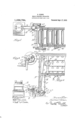
- Figure 1 is a plan View showing one end of the proofing conveyer i itself, together with the automatic devices which are the subject of this invention.
- Fig. v is a plan View showing one end of the proofing conveyer i itself, together with the automatic devices which are the subject of this invention.
- Fig. 2 is a side elevation of the partsshown in Fig. 1.
- Fig. 3 is a detail View of the clutchoperating mechanism for the transferring drum.
- a delivery chute at B, inclined downwardly and terminating in a hinged portion, B, whose extreme lower end is composed of a series of upwardly,v rounded fingers, B2,
- a transferring drum, C is mounted for rotation upon a shaft, C1, extending transversely of the chute', B, just beyond its terminatin, and this drum, C, ⁇ is provided with outwardly extending curved.
- ngeis, C2 quite similar to the fingers, B2, of the chute,but so positioned upon. the drum, C, as to pass between the lingers, B2, as the drum is rotated.
- the drum, C is provided with twesetsof fingers, C, arranged thereon at diametri'- cally opposite points, but this arrangement is only preferred and not essential.'
- the dough being picked up by the fingers, C2 is carried over with the drum about onchalf revolution and is dropped upon a horizontally traveling apron, D, moving in the direction indicated by the arrow in Fig. 1.
- the driving connections for this apron, D, and the transferring drum, C, are geared together so 'that if the chute, B, is kept adequately supplied with balls of dough, these balls will be delivered upon the apron, D, at regular intervals and will thus be regularly spaced from one another thereon.
- the prooling conveyor proper is mountedI adjacent to the apron, D.
- .lt consists merely (so far as this invention is concerned), of an endless link belt, E, provided at regular intervals with trough-shaped buckets, F, pivotally suspended from the belt so as to be gravitationally held in proper position and prevented from ejecting their contents as the belt passes over its various guide wheels,-Gr.
- the apron D is driven through bevel gears, H1 and H2, which are in turn actuated through sprocket wheels, and a drive chain, J, arranged 'to transmit power from one of the guide wheels, G, of i the proofing conveyor.
- the ejection of the loaves from the apron, D', and their delivery into the buckets, F, is accomplished by a reciprocating pusher, K, consisting off a pusher-board, K1, whose length in the direction of travel of the ⁇ apron, D, is substantially equal to thel length mension the transferring drum, C, is arrangedto deliver the four loaves desired.
- the pusher-board, K1' is carried by a lever arm-y pivotedin a floor bracket, K2, under the apron, D, and formed to reach around ⁇ and -above the apron.
- the four loaves are thus simultaneously shoved ofi the apron, D, into fthe bucket, F, which continues its upward travel at such a rate relatively tothe movement of the apron, D, that the next bucket, F, shall just'come into receiving position when the-next four Vloaves shall have ar- ,rived opposite .it upon the a ron, D.
- the drum, C will always come -to rest with one of the 'clutch bolts, Q, directly opposite the upper end of the presser arm, P, so that this means are the linkage being so arranged thaty ythe upper end ofthe presser arinjs moved "towar means;
- the present a', 'arat-us is provided in the proofing room wifhial series of open water troughs, T, through' which there are )laid steam pipes, S, it bein -intended that 'the hea-tof the steam shall e taken up by the ⁇ water so as to cause rslow evaporation of the latter in order ,to keep the atmosphere of the room properly'jmoistened.
- Fig. 2 shows also a water'suppl pipe, W, which may be controlled byv any esired form of automatic valve so as to maintainC a constant water level in the trough, '11.
- a rotary element/ I mounted for ⁇ revolution about an vaxis ex- Losanna tending transversely of. the direction of the chute, said rotary element being provided with outwardly extending fingers positioned to register with the intervals between the fingers of the chute and thus adapted to pass between said fingers of the chute, a receiver for the material posit-ioned at the opposite side of the rotary element from that to which the chute is adjacent, and means for revolving said rotary element.
- an inclined chute terminating in a series of fingers extending in the direction of the chute, a shaft extending transversely of said direction of the chute beyond the end thereof, a drum mounted upon said shaft and provided with outwardly extending ngers positioned to register with the intervals between the fingers of the chute and thus adapted to pass said fingers when t-he drum ⁇ is revolved, a portion of the chute being depressible by the weight of. material thereon, a clutch device adapted to engage the drum with the shaft, operating .means for said clutch device connected with the depressible portion of the chute, and means for revolving the shaft.
- an inclined chute terminating in a series of fingers extending in the direction of the chut-e, a shaft extending transversely of said direction of the chute beyond the end thereof, a drum mounted upon said shaft and provided with outwardly extending lingers positioned to register with the intervals between the fingers of the chute and thus adapted to pass said fingers when ⁇ the drum is revolved, a portion of the chute being depressible by the weightv of material thereon, a clutch device comprising a notch in the shaft and a radially movable clutch 'bolt in the drum, a presser arm positionable to engage the outer end of the clutch bolt for thrusting said bolt into the notch of the shaft, a linkage connecting said presser arm with the depressible portion of the chute, 85 a pin extending from the end of the drum at a point radially beyond the outer end of the clutchv bolt, the presser arm having an extension adapted to engage said pin for arresting the drum when said presser arm stands
- a device for the purpose indicated an inclined chute ⁇ terminating in a series of iingers extending in the direction of the chute, a shaft extending transversely of said direction o-f the chute beyond the end thereof, a drum mounted upon said shaft and provided with outwardly extending lingers positioned to register with the intervals between the lingers of the chute and thus 190 l adapted to pass said iingers when the drum is revolved, a portion of the chute being depressible by the weight of material thereon, a clutch device comprising a notch in the shaft and a radially movable clutch bolt inv the drum, a presser arm positionable to engage the outer end of the clutch bolt for thrusting said bolt into the notch of the shaft, a linkage connecting said presser arm with the depressible portion of the chute, a 11o wedge fixedly mounted in the path of rotation of the outer end of the clutch bolt substantially diametrically opposite the presser arm, the clutch bolt being adapted for engagement by said wedge and the
Landscapes
- Engineering & Computer Science (AREA)
- Mechanical Engineering (AREA)
- Manufacturing And Processing Devices For Dough (AREA)
Description
S. OLSON. BREAD PROOFING APPARATUS.
APPLIoA'moN FILED JAN. a. 1912.
Patented Sept. 17, 1912.
ICE.
SAMUEL OLSON, OF CHICGU, ILLINOIS.
BREAD-rancune erranarus.
Speoicetion of Letters Patent.
Patented Sept. 1'?, 1912.
Application led January 8, 1912. Serial No. 669,960.
Y' To cllwhom it may Gomera.'
-of the bread during this portion of the` process.
It consists of the features and elements of construction described and shown in the drawings as indicated in the claims.
ln the drawings: Figure 1 is a plan View showing one end of the proofing conveyer i itself, together with the automatic devices which are the subject of this invention. Fig. v
2 is a side elevation of the partsshown in Fig. 1. Fig. 3 is a detail View of the clutchoperating mechanism for the transferring drum.
There is conventionally illustrated at A; a machine-known in the art as the rounderup or beller whose function is to form the dough into substantially spherical units. f
Leading from the baller there is shown a delivery chute at B, inclined downwardly and terminating in a hinged portion, B, whose extreme lower end is composed of a series of upwardly,v rounded fingers, B2,
designed to arrest the movement of the ballshaped unit of dough as it is delivered from the baller, A.
A transferring drum, C, is mounted for rotation upon a shaft, C1, extending transversely of the chute', B, just beyond its terminatin, and this drum, C, `is provided with outwardly extending curved. ngeis, C2, quite similar to the fingers, B2, of the chute,but so positioned upon. the drum, C, as to pass between the lingers, B2, as the drum is rotated. In this way, by the rotation of the drum the ball of dough which is held by the lingers, B2, will' be picked up by the fingers, C2, as they pass between the ngers, B2', if the drum is rotated in clock-wise: direction, as viewed: in Fig. 2. As shown, thedrum, C, is provided with twesetsof fingers, C, arranged thereon at diametri'- cally opposite points, but this arrangement is only preferred and not essential.'
The dough being picked up by the fingers, C2, is carried over with the drum about onchalf revolution and is dropped upon a horizontally traveling apron, D, moving in the direction indicated by the arrow in Fig. 1. The driving connections for this apron, D, and the transferring drum, C, are geared together so 'that if the chute, B, is kept suficiently supplied with balls of dough, these balls will be delivered upon the apron, D, at regular intervals and will thus be regularly spaced from one another thereon. The prooling conveyor proper, is mountedI adjacent to the apron, D. .lt consists merely (so far as this invention is concerned), of an endless link belt, E, provided at regular intervals with trough-shaped buckets, F, pivotally suspended from the belt so as to be gravitationally held in proper position and prevented from ejecting their contents as the belt passes over its various guide wheels,-Gr.
It is desired to transfer the balls of dough from the apron, D, into the buckets, F, so that each bucket shall contain four such balls or loaves equally spaced apart. For this reason, that part of the proofing conveyer which is nearest the apron, D, is arranged for vertical travel, the buckets moving upward past the side of the apron, D. The direction of travelof the conveyor is thus transverse to the direction of travel of the apron and its path may be said to be laterally adjacent to the path' of travel of the apron. The apron D, is driven through bevel gears, H1 and H2, which are in turn actuated through sprocket wheels, and a drive chain, J, arranged 'to transmit power from one of the guide wheels, G, of i the proofing conveyor. l
The ejection of the loaves from the apron, D', and their delivery into the buckets, F, is accomplished by a reciprocating pusher, K, consisting off a pusher-board, K1, whose length in the direction of travel of the` apron, D, is substantially equal to thel length mension the transferring drum, C, is arrangedto deliver the four loaves desired. The pusher-board, K1', is carried by a lever arm-y pivotedin a floor bracket, K2, under the apron, D, and formed to reach around `and -above the apron. A pitman, L, connec'te'd at one end tothe lever arm, K, and
of oneY of the buckets, .F, within which dii" provided at its opposite end with a follower?V roller, L1, in contact with a cam, M, is intended to communicate reciprocation 'to the pusher. The cam, M, is rlgidly connected Vwith the nearest ofv the idlers or guide wheels, G, and is thus driven by the travel t pusher, K, at the instant when four loaves carried by the apron, D, come to the osition opposite one ofthe buckets, F, o the proofing conveyer. The four loaves are thus simultaneously shoved ofi the apron, D, into fthe bucket, F, which continues its upward travel at such a rate relatively tothe movement of the apron, D, that the next bucket, F, shall just'come into receiving position when the-next four Vloaves shall have ar- ,rived opposite .it upon the a ron, D.
It is vconceivable and pro able that occasionally the baller, A, may fail to deliver the loaves exactly on time and it willwbe seen that if -sucha loaf or ball of dou h should be delivered just a moment too ate Vto be picked up by the fngers,-C1, it would encounter the points of thesel fin ers andv would-become hopelessly deforme besides so smearing up lthe fingers and the drum, C,
g as to seriously interfere with the operation of the machine. To meet this contingency is the purpose of the hinging of the terminal portion, B1, of the chute, B. Extending downwardly from the pivot or hinge of this v member, B1, there is shown a bell crank arm,/B, to which there is pivotally connected alink, N, extendin to the lower end of a pivoted' presser arm, The shaft,C 1, as maybe noted from Fig. 3, is provided with a collar, C', having notches, C4, formed l disengaged from the'...notches, C, o shaft but whenever'a loaf of dough arrivesl in its' periphery, and each dimensloned to receive the inner end of one of the clutch bolts, Q, which are lslidably carried in the hub, C", of the drum. The normal position of the clutch bolts is that in which thety h upon the terminal portion, B1, of the chute, this terminal portlon will be .sli htly depressed or rocked about its hin'e ivot, thus movin lthe lever arm, B, an "t e. presser arm,
the shaft, C1 ar enough "tffpush one of the clutch bolts, Q,ii1to engar ement with one o f-the notches, C4, as the s aft, C1, revolves to a position permittin this action.
. 'As willbehereinafter explaine ,the drum, C, will always come -to rest with one of the 'clutch bolts, Q, directly opposite the upper end of the presser arm, P, so that this means are the linkage being so arranged thaty ythe upper end ofthe presser arinjs moved "towar means;
of throwing in the clutch will alwaysbe operative; since the shaft, C1, is continuously revolving, its notches, C1, will however, notA always be in position to receive thelr clutch bolt,'Q, but this will merely result in slightly delayin the de ression of the'element, B1. of thescute, an since the weight of the loaf is there present, the above described act-ion will-take placel assoon as the notch, C4, becomes reglstered-with the bolt, Q. To prevent the continuous rotation'of the drum in case the next loaf is not delivered promptly enough tohold the presser arm, P, 1n operative position and'thus insert the other clutch bolt, Q, into its corres onding notch, C, there is' provided atthe arside of the drum from the chute, a wedge-shaped guide, R, positioned to engage the head of the clutch bolt as it passes, and thus to withdraw the bolt from the notch, C4. Just as. the bolt is withdrawma pin, C, projecting from the end of the drum,l C,\w1ll be caught by the square-hookedV end, P1, of the presser arm, if
position by reason of the non-arrival of the the presser arm has returned to its normal next loaf upon the hinged portion of the chute, B1. Since .the clutch bolts, Q, the notches, C, and the pins, C, are all-provided in duplicate, the minimum dela of the drum by reason of late arrival o the dough will amount to a half revolution, but as the travel ofthe apron, D, is not retarded or arrested, this delay ofthe transferring drum, C, will result in the omissionof one loaf from the regular `quota of four.
It is wellunderstood by those familiar with the art that the purpose of the proofing conveyeris to carry the loaves of dough into a properly heated, .closed room, and to a'llow them to remain therein fora certain' specified length of time in which they will rise or become light. It is also well known that if the atmosphere of this room be too dry, there will be formed an outer skin on each loaf which upon baking, becomes a crust-which is'. thicker and tougher than desirable. To 'prevent the'zffformation of such a surface, the present a', 'arat-us is provided in the proofing room wifhial series of open water troughs, T, through' which there are )laid steam pipes, S, it bein -intended that 'the hea-tof the steam shall e taken up by the `water so as to cause rslow evaporation of the latter in order ,to keep the atmosphere of the room properly'jmoistened. Fig. 2 shows also a water'suppl pipe, W, which may be controlled byv any esired form of automatic valve so as to maintainC a constant water level in the trough, '11.
I claim c 1. In a device for the purpose indicated, an inclined chute terminating at its lower end lin a series of fingers extending in-the,
direction of the chute, a rotary element/ I mounted for` revolution about an vaxis ex- Losanna tending transversely of. the direction of the chute, said rotary element being provided with outwardly extending fingers positioned to register with the intervals between the fingers of the chute and thus adapted to pass between said fingers of the chute, a receiver for the material posit-ioned at the opposite side of the rotary element from that to which the chute is adjacent, and means for revolving said rotary element.
2. In a device for the purpose indicated, an inclined chute terminating in a series of fingers extending in the direction of the chute, a shaft extending transversely of said direction of the chute beyond the end thereof, a drum mounted upon said shaft and provided with outwardly extending ngers positioned to register with the intervals between the fingers of the chute and thus adapted to pass said fingers when t-he drum `is revolved, a portion of the chute being depressible by the weight of. material thereon, a clutch device adapted to engage the drum with the shaft, operating .means for said clutch device connected with the depressible portion of the chute, and means for revolving the shaft.
3. In a device for the purpose indicated, an inclined chute terminating in a series of fingers extending in the direct-ion of the chute, a shaft extending transversely of said of the chute, and means for revolving the i chute, a shaft extending transversely of said direct-ion of the chute beyond the end thereof, a drum mounted upon said shaft and provided with outwardly extending fingers positioned to register with the intervals between the fingers of the chute and thus adapted to pass said lingers when the drum is revolved, a portion of the chute being depressible by the weight of material thereon, a clutch device comprising a notch in the shaft and a radially movable clutch bolt in the drum, a presser arm positionable to engage the outerv end of the clutch bolt for thrusting said bolt into the notch of the shaft, a linkage connecting said presser arm with the depressible portion of the chute, and means for revolving the shaft.
5. ln a device for the purpose indicated, an inclined chute terminating in a series of fingers extending in the direction of the chut-e, a shaft extending transversely of said direction of the chute beyond the end thereof, a drum mounted upon said shaft and provided with outwardly extending lingers positioned to register with the intervals between the fingers of the chute and thus adapted to pass said fingers when `the drum is revolved, a portion of the chute being depressible by the weightv of material thereon, a clutch device comprising a notch in the shaft and a radially movable clutch 'bolt in the drum, a presser arm positionable to engage the outer end of the clutch bolt for thrusting said bolt into the notch of the shaft, a linkage connecting said presser arm with the depressible portion of the chute, 85 a pin extending from the end of the drum at a point radially beyond the outer end of the clutchv bolt, the presser arm having an extension adapted to engage said pin for arresting the drum when said presser arm stands out of position for engaging the bolt.
6. ln a device for the purpose indicated, an inclined chute `terminating in a series of iingers extending in the direction of the chute, a shaft extending transversely of said direction o-f the chute beyond the end thereof, a drum mounted upon said shaft and provided with outwardly extending lingers positioned to register with the intervals between the lingers of the chute and thus 190 l adapted to pass said iingers when the drum is revolved, a portion of the chute being depressible by the weight of material thereon, a clutch device comprising a notch in the shaft and a radially movable clutch bolt inv the drum, a presser arm positionable to engage the outer end of the clutch bolt for thrusting said bolt into the notch of the shaft, a linkage connecting said presser arm with the depressible portion of the chute, a 11o wedge fixedly mounted in the path of rotation of the outer end of the clutch bolt substantially diametrically opposite the presser arm, the clutch bolt being adapted for engagement by said wedge and the wedge being formed to cause withdrawal of the bolt from the notch by such engagement,
,and means for revolving the shaft,
ln testimony whereof have hereunto set my hand at Chicago, lllinois, this 5th 12o day of January, 1912.
'sartene etsen.
Witnesses:
Enna M. MAoINTosn, M. GERTRUDE ADY.
Priority Applications (1)
| Application Number | Priority Date | Filing Date | Title |
|---|---|---|---|
| US66996012A US1038784A (en) | 1912-01-08 | 1912-01-08 | Bread-proofing apparatus. |
Applications Claiming Priority (1)
| Application Number | Priority Date | Filing Date | Title |
|---|---|---|---|
| US66996012A US1038784A (en) | 1912-01-08 | 1912-01-08 | Bread-proofing apparatus. |
Publications (1)
| Publication Number | Publication Date |
|---|---|
| US1038784A true US1038784A (en) | 1912-09-17 |
Family
ID=3107061
Family Applications (1)
| Application Number | Title | Priority Date | Filing Date |
|---|---|---|---|
| US66996012A Expired - Lifetime US1038784A (en) | 1912-01-08 | 1912-01-08 | Bread-proofing apparatus. |
Country Status (1)
| Country | Link |
|---|---|
| US (1) | US1038784A (en) |
Cited By (1)
| Publication number | Priority date | Publication date | Assignee | Title |
|---|---|---|---|---|
| US2931483A (en) * | 1954-05-17 | 1960-04-05 | Baker Perkins Inc | Rack proofing apparatus |
-
1912
- 1912-01-08 US US66996012A patent/US1038784A/en not_active Expired - Lifetime
Cited By (1)
| Publication number | Priority date | Publication date | Assignee | Title |
|---|---|---|---|---|
| US2931483A (en) * | 1954-05-17 | 1960-04-05 | Baker Perkins Inc | Rack proofing apparatus |
Similar Documents
| Publication | Publication Date | Title |
|---|---|---|
| US4513656A (en) | Sandwich machine | |
| GB2186855A (en) | Tray loading method and apparatus | |
| US2732057A (en) | Bakery conveyor system | |
| US2704614A (en) | Material handling apparatus | |
| US3085520A (en) | Machine for production of frozen confections | |
| US1985547A (en) | Delivery mechanism | |
| US2642010A (en) | Device for depositing centers in candy pieces | |
| US2804192A (en) | Automatic feeding arrangement from bread cooler to bread slicers and wrappers | |
| US2910017A (en) | Automatic cookie feeder for deposition and sandwiching | |
| US444379A (en) | And charles | |
| US1351018A (en) | Biscuit-stacking machine | |
| US3757833A (en) | Depositing apparatus | |
| US2595022A (en) | Selective article spacing apparatus for conveyers | |
| US1756222A (en) | Cherry dropper | |
| US1786108A (en) | Cluster enrobing machine | |
| US1770222A (en) | Dough-handling apparatus | |
| US2273735A (en) | Machine for filling forms with biscuit material | |
| US1896210A (en) | Filling and measuring machine | |
| US1694263A (en) | Cherry-pitting machine | |
| US3460191A (en) | Food molding machine | |
| US3439632A (en) | Multiflow dough-forming machine for fancy baked goods | |
| US1973625A (en) | Feeding mechanism | |
| US2821314A (en) | Turnover mechanisms for depanning machines | |
| US3297248A (en) | Fruit counter with improved conveyor and cammed switch operator | |
| US3244121A (en) | Apparatus for manufacturing frozen confections |