US10384226B2 - Spray gun filter for filtering liquid - Google Patents
Spray gun filter for filtering liquid Download PDFInfo
- Publication number
- US10384226B2 US10384226B2 US13/822,042 US201113822042A US10384226B2 US 10384226 B2 US10384226 B2 US 10384226B2 US 201113822042 A US201113822042 A US 201113822042A US 10384226 B2 US10384226 B2 US 10384226B2
- Authority
- US
- United States
- Prior art keywords
- filter
- spray gun
- support
- filter support
- housing
- Prior art date
- Legal status (The legal status is an assumption and is not a legal conclusion. Google has not performed a legal analysis and makes no representation as to the accuracy of the status listed.)
- Active
Links
Images


Classifications
-
- B—PERFORMING OPERATIONS; TRANSPORTING
- B05—SPRAYING OR ATOMISING IN GENERAL; APPLYING FLUENT MATERIALS TO SURFACES, IN GENERAL
- B05B—SPRAYING APPARATUS; ATOMISING APPARATUS; NOZZLES
- B05B15/00—Details of spraying plant or spraying apparatus not otherwise provided for; Accessories
- B05B15/40—Filters located upstream of the spraying outlets
-
- B—PERFORMING OPERATIONS; TRANSPORTING
- B01—PHYSICAL OR CHEMICAL PROCESSES OR APPARATUS IN GENERAL
- B01D—SEPARATION
- B01D29/00—Filters with filtering elements stationary during filtration, e.g. pressure or suction filters, not covered by groups B01D24/00 - B01D27/00; Filtering elements therefor
- B01D29/01—Filters with filtering elements stationary during filtration, e.g. pressure or suction filters, not covered by groups B01D24/00 - B01D27/00; Filtering elements therefor with flat filtering elements
- B01D29/05—Filters with filtering elements stationary during filtration, e.g. pressure or suction filters, not covered by groups B01D24/00 - B01D27/00; Filtering elements therefor with flat filtering elements supported
-
- B—PERFORMING OPERATIONS; TRANSPORTING
- B05—SPRAYING OR ATOMISING IN GENERAL; APPLYING FLUENT MATERIALS TO SURFACES, IN GENERAL
- B05B—SPRAYING APPARATUS; ATOMISING APPARATUS; NOZZLES
- B05B9/00—Spraying apparatus for discharge of liquids or other fluent material, without essentially mixing with gas or vapour
- B05B9/03—Spraying apparatus for discharge of liquids or other fluent material, without essentially mixing with gas or vapour characterised by means for supplying liquid or other fluent material
- B05B9/04—Spraying apparatus for discharge of liquids or other fluent material, without essentially mixing with gas or vapour characterised by means for supplying liquid or other fluent material with pressurised or compressible container; with pump
- B05B9/0403—Spraying apparatus for discharge of liquids or other fluent material, without essentially mixing with gas or vapour characterised by means for supplying liquid or other fluent material with pressurised or compressible container; with pump with pumps for liquids or other fluent material
-
- B—PERFORMING OPERATIONS; TRANSPORTING
- B01—PHYSICAL OR CHEMICAL PROCESSES OR APPARATUS IN GENERAL
- B01D—SEPARATION
- B01D2201/00—Details relating to filtering apparatus
- B01D2201/04—Supports for the filtering elements
-
- B—PERFORMING OPERATIONS; TRANSPORTING
- B01—PHYSICAL OR CHEMICAL PROCESSES OR APPARATUS IN GENERAL
- B01D—SEPARATION
- B01D2201/00—Details relating to filtering apparatus
- B01D2201/04—Supports for the filtering elements
- B01D2201/0407—Perforated supports on both sides of the filtering element
-
- B—PERFORMING OPERATIONS; TRANSPORTING
- B01—PHYSICAL OR CHEMICAL PROCESSES OR APPARATUS IN GENERAL
- B01D—SEPARATION
- B01D2201/00—Details relating to filtering apparatus
- B01D2201/04—Supports for the filtering elements
- B01D2201/0415—Details of supporting structures
Definitions
- the invention relates to a spray gun filter, which is arranged on, or in the vicinity of, the spray gun and is suitable for filtering liquid, such as coating material.
- the spray gun filter 100 shown in FIGS. 1 and 2 was used in spray guns 110 .
- the spray gun filter 100 comprises a tubular filter support 101 and a tubular filter fabric 102 , which surrounds the outer lateral surface of the filter support.
- Coating material F is pressed externally through the filter fabric 102 under pressure, generally between 80 and 500 bar, and then flows along a channel 103 , which is located between the filter fabric 102 and the filter support 101 .
- outlet openings 104 are provided, which connect the channel 103 to the interior 105 of the filter support 101 .
- the coating material F thus flows through the channel 103 and the outlet openings 104 into the interior 105 of the filter support 101 .
- the spray gun filter 100 has the disadvantage that the filter residues remain in the filter housing 112 , 116 of the spray gun 112 when the spray gun filter 100 is removed.
- the spray gun filter 100 has the disadvantage that a spring 111 is necessary in order to fix the spray gun filter 100 in the correct position in the filter housing 112 , 116 .
- a further disadvantage of the spray gun filter 100 is that it has a dead space 106 at the upstream end, said dead space increasing the overall length of the spray gun filter 100 and therefore also of the filter housing 112 , 116 .
- An object of the invention is to specify a spray gun filter for filtering liquid, said spray gun filter having a longer service life and at the same time smaller dimensions.
- an additional component such as the spring in the embodiment according to FIG. 2
- the production costs can thus be reduced. Since the additional component is omitted, it can also no longer become lost and also does not have to be cleaned. The maintenance effort for the personnel is reduced and the risk of the spring and the spray gun filter being inserted incorrectly into the filter housing is likewise reduced.
- a further advantage of the spray gun filter according to the invention lies in the fact that no filter residues and impurities remain in the filter housing of the spray gun once the spray gun filter has been removed from the filter housing.
- the spray gun filter according to the invention generates a lower pressure loss.
- the handling of the entire spray gun, and in particular the disassembly, is also improved. If coating material has solidified in the filter housing, the spray gun filter according to FIG. 1 can only be removed from the filter housing by applying force. It is often even necessary to use a tool for this purpose. In order to remove the spray gun filter according to the invention from the filter housing, much less force is necessary. There is generally no need to use a tool for this purpose.
- the spray gun filter according to the invention no longer has any dead space compared to the spray gun filter according to FIG. 1 .
- the total length of the spray gun filter and also the length of the filter housing are thus reduced.
- the total weight of the spray gun is reduced by the weight saving with the spray gun filter, by the weight saving with the filter housing and by the weight saving with the coating material.
- the object is achieved by a spray gun filter for filtering liquid having the features specified in claim 1 .
- the spray gun filter according to the invention for filtering liquid comprises a filter fabric and a filter support, which has outlet openings for the liquid and which surrounds the filter fabric from the outside.
- the outlet openings are distributed over the length of the filter support. This has the advantage that the pressure bearing on the filter support is distributed uniformly. The filter support can thus be produced with thinner walls and using less material.
- the filter support is externally conical. It can thus be removed more easily from the spray gun. This is advantageous in particular if coating material has hardened in the filter housing of the spray gun and the spray gun filter has become stuck to the filter housing.
- the filter support is open at one end and is closed at the other end.
- the filter fabric is produced from wire or a sintered, liquid-permeable material.
- the filter fabric made of wire is robust and has a long service life.
- the filter fabric is substantially cylindrical.
- a filter fabric shaped in this way can be produced easily. Filter fabric from a roll can be used as starting material, which is cut to size, rolled to the desired diameter and welded at the seam.
- the cylindrically shaped filter fabric can be easily fitted into the filter support and connected thereto.
- said invention can be improved yet further by producing the filter support from polyamide, polypropylene, polyethylene or polyoxymethylene. These materials can be injection moulded, and therefore the filter support can be produced cost effectively in high numbers.
- the spray gun filter with a filter support produced from one of these materials is stable enough to withstand pressures between 80 and 500 bar.
- the spray gun filter according to the invention may have a sleeve, in which the filter support is arranged and with which the filter support and the sleeve are formed in such a way that they form a channel for the filtered liquid.
- the sleeve As a result of the sleeve, the filtered liquid is prevented from coming into contact with the filter housing of the spray gun. If the liquid hardens in the spray gun filter, the spray gun filter does not stick to the filter housing, and it is therefore ensured even in this case that the spray gun filter can be easily removed from the filter housing.
- a spray gun with which a filter housing is provided and with which the outer face of the filter support bears against the filter housing is also proposed.
- the spray gun has the above-mentioned advantages.
- the filter support and the filter housing are formed in such a way that they together form a channel for the liquid.
- the filter support and the filter housing are formed in such a way that they together form a plurality of channels, which are interconnected. The pressure loss caused by the spray gun filter is thus reduced yet further.
- the filter housing comprises a first and a second housing part, wherein the two housing parts are interconnected by means of a releasable connection.
- the connection may be a screw connection for example.
- the filter housing has a shoulder, on which the filter support is supported.
- the shoulder can be used as a stop in order to define the axial position of the spray gun filter. As soon as liquid is pressed under pressure into the spray gun filter, the filter support is pressed against the stop.
- a spraying system that comprises a spray gun, a tube line and a spray gun filter is also proposed, wherein the spray gun filter is arranged between two tube portions of the tube line.
- the spray gun filter can be used for water-soluble paint, solvent-containing paint, multi-component paint, primer, anti-corrosion agents or oil.
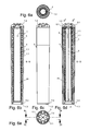
- FIG. 1 shows a side view of a spray gun filter that is already known, wherein one part is illustrated in a cut-away manner.
- FIG. 2 shows a sectional side view of part of a spray gun with the known spray gun filter.
- FIG. 3 shows a first possible embodiment of the spray gun filter according to the invention in a side view and as viewed from the filter head.
- FIG. 4 shows a longitudinal sectional view of the first possible embodiment of the spray gun filter according to the invention.
- FIG. 5 shows an exploded view of the first possible embodiment of the spray gun filter according to the invention.
- FIG. 6 a shows a second possible embodiment of the spray gun filter according to the invention as viewed from the inlet side.
- FIG. 6 b shows the second embodiment of the spray gun filter according to the invention in longitudinal section taken along the line of section B-B.
- FIG. 6 c shows a side view of the second embodiment of the spray gun filter.
- FIG. 6 d shows the second embodiment of the spray gun filter in longitudinal section taken along the line of section D-D.
- FIG. 6 e shows the second embodiment of the spray gun filter according to the invention as viewed from the filter head.
- FIG. 7 a shows a third possible embodiment of the spray gun filter according to the invention in longitudinal section taken along the line of section B-B.
- FIG. 7 b shows a side view of the third embodiment of the spray gun filter.
- FIG. 7 c shows the third embodiment of the spray gun filter as viewed from the filter head.
- FIG. 8 a shows a fourth possible embodiment of the spray gun filter according to the invention in longitudinal section taken along the line of section B-B.
- FIG. 8 b shows a side view of the fourth embodiment of the spray gun filter.
- FIG. 8 c shows the fourth embodiment of the spray gun filter as viewed from the filter head.
- FIG. 9 shows a sectional view of the first embodiment of the spray gun filter according to the invention as installed in a spray gun.
- FIG. 10 shows a three-dimensional view of a spray gun with a spray gun filter according to the invention.
- FIG. 11 shows an exploded view of the spray gun with the spray gun filter according to the inven-tion.
- FIG. 12 shows part of a coating system, with which the spray gun filter according to the invention is installed in the tube line, which leads to the spray gun.
- a spray gun will be understood to mean a gun for atomising or spraying a liquid, such as water-soluble paint, solvent-containing paint, multi-component paint, primer, dispersion, oil or anti-corrosion agents.
- a paint gun is likewise a spray gun intended for painting surfaces and is formed accordingly for the paints to be sprayed.
- the spray gun filter according to the invention is particularly suitable for filtering coating material, primer, anti-corrosion agents or oil.
- coating material water-soluble paints, solvent-containing paints, metallic paints, stains, dispersions and multi-component paints will also be referred to as coating material.
- Fine-mesh filter fabrics are used with stains, clear varnishes and other low-viscosity spraying materials.
- FIG. 3 shows a first possible embodiment of the spray gun filter according to the invention in a side view and in a front view, that is to say as viewed from the filter head 1 . 2 .
- the first embodiment of the spray gun filter according to the invention is illustrated in longitudinal section in FIG. 4 .
- FIG. 5 shows the first embodiment of the spray gun filter according to the invention in an exploded view.
- the spray gun filter comprises a tubular filter support 1 and a cylindrical filter fabric 2 arranged within the filter support 1 .
- the outer face 2 . 2 of the filter fabric 2 bears against the inner face of the filter support 1 .
- the filter support 1 comprises an inlet 1 . 3 , through which liquid F to be filtered flows into the interior 24 of the spray gun filter. From here, the liquid F is pressed outwardly through the filter fabric 2 , wherein particles, impurities and clumps are retained inside the spray gun filter. The retained material R is illustrated symbolically in FIG. 4 .
- the filtered liquid F passes through a series of outlet openings 1 . 1 , which are provided in the filter support 1 , and flows out again from the spray gun filter.
- the filter support 1 further comprises a plurality of radial protruding supporting elements 1 . 5 , which are provided to bear against the filter housing 12 . The filtered liquid then flows between the filter support 1 and the filter housing 12 , 16 (see FIG.
- the filtered liquid passes through the channels provided in the filter head 1 . 2 into the material channel 16 . 2 .
- the outer surface of the filter support 1 may include a plurality of radial protruding supporting elements 1 . 5 . These supporting elements 1 . 5 bear against the filter housing 12 , 16 when the filter support 1 is inserted into the filter housing 12 , 16 .
- the filter support 1 may have, externally, a cylindrical portion 8 and a conical portion 9 .
- the diameter D 3 in the inlet region 1 . 3 is smaller than the diameter D 2 at the filter head 1 . 2 .
- Such a geometry has the advantage that the spray gun filter can be removed more easily from the filter housing 12 , 16 (see FIG. 9 ).
- the application of force necessary in order to remove the spray gun filter from the filter housing 12 , 16 can be considerably reduced by a such a geometry.
- the filter fabric 2 has a substantially cylindrical shape.
- a filter fabric from a roll can be used as starting material, which is cut to size, rolled to the desired diameter and welded or glued at the seam 4 .
- the filter fabric 2 is then inserted into the filter support 1 and connected thereto, for example by a glued or welded joint 3 .
- the seal 1 . 4 is formed as a lip seal in the embodiment according to FIGS. 3, 4 and 5 .
- the lip seal 1 . 4 bears against the filter housing 12 and seals the inlet 1 . 3 of the spray gun filter with respect to the outlet openings 1 . 1 thereof.
- FIGS. 6 a , 6 b and 6 c A second possible embodiment of the spray gun filter according to the invention is illustrated in FIGS. 6 a , 6 b and 6 c as viewed from the inlet side, in longitudinal section taken along the line of section B-B, and in a side view.
- FIGS. 6 d and 6 e show the second embodiment of the spray gun filter in longitudinal section taken along the line of section D-D and as viewed from the front.
- the second embodiment basically differs from the first embodiment in that an additional sleeve 5 is provided, in which the filter support 1 is fitted together with the filter fabric.
- the outlet openings 5 . 1 in the spray gun filter are located at the filter head 1 . 2 .
- the filtered liquid F is guided through the channel 6 and only exits from the spray gun filter at the filter head 1 . 2 through the outlet openings 5 . 1 , it does not come into contact with the filter housing 12 , 16 of the spray gun 10 . If the liquid F in the spray gun filter hardens, the spray gun filter does not stick to the filter housing 12 , 16 . The force applied to remove the spray gun filter can thus be reduced yet further compared to the first embodiment.
- a further advantage is that the user does not come into contact with the liquid F when removing the spray gun filter and his hands therefore remain clean.
- FIGS. 7 a , 7 b and 7 c show a third possible embodiment of the spray gun filter according to the invention in longitudinal section taken along the line of section B-B in a side view and as viewed from the inlet side.
- the third embodiment basically differs from the second embodiment in that a sleeve 22 is provided, in which the filter fabric 2 is fitted.
- the sleeve 22 is used as a filter support for the filter fabric 2 and, together therewith, forms a channel 6 , through which the filtered liquid F is transported away.
- the outlet openings 22 . 6 are located at the filter head 22 . 2 in the third embodiment.
- the filtered liquid F does not come into contact with the filter housing 12 , 16 of the spray gun 10 . If the liquid F hardens in the spray gun filter, the spray gun filter does not stick to the filter housing 12 , 16 . The force applied to remove the spray gun filter can thus be reduced yet further compared to the first embodiment.
- FIGS. 8 a , 8 b and 8 c A fourth possible embodiment of the spray gun filter according to the invention is illustrated in FIGS. 8 a , 8 b and 8 c in longitudinal section taken along the line of section B-B, in a side view, and as viewed from the inlet side.
- the fourth embodiment basically differs from the third embodiment by the inner shape of the sleeve, which surrounds the filter fabric 1 .
- the sleeve 23 On its inner face, the sleeve 23 has a series of grooves 23 . 7 running in the longitudinal direction, which, together with the filter fabric 2 , form a series of channels 6 , through which the filtered liquid F is transported to the outlet openings 23 . 6 .
- the outlet openings 23 . 6 in the spray gun filter are located at the filter head 23 . 2 , as in the third embodiment.
- All embodiments of the spray gun filter according to the invention function in the same manner in principle.
- the liquid F to be filtered passes through an inlet opening 1 . 3 , 22 . 3 or 23 . 3 into the interior 24 of the spray gun filter, where it is then pressed outwardly through the filter fabric 2 , wherein the impurities are retained in the interior 24 of the spray gun filter.
- FIG. 9 shows a sectional view of the first embodiment of the spray gun filter according to the invention as installed in a spray gun 10 .
- the filter housing for the spray gun filter comprises an upstream housing part 12 and a downstream housing part 16 . Both housing parts 12 and 16 are interconnected via a releasable connection 17 , for example a screw connection.
- the two housing parts 12 and 16 are surrounded in part by a grip piece 11 , which facilitates the connection and separation of the housing parts 12 and 16 .
- a seal 15 ensures that no liquid F can escape at the connection point 17 .
- the upstream housing part 12 is connected to a hinge joint 13 , which carries a coupling 13 . 1 at the upstream end for the connection of a supply line.
- a sleeve 20 is arranged within the hinge joint 13 and protrudes into the interior of the upstream housing part 12 .
- Two ring seals 18 and 19 are provided to seal the hinge joint 13 .
- the sleeve 20 is pressed permanently against the two ring seals 18 and 19 via a compression spring 14 .
- the upstream housing part 6 has a shoulder 16 . 1 in the interior, said shoulder being used as a stop for the spray gun filter.
- the downstream housing part 16 discharges into the part of the spray gun 10 containing the valve needle for the spray nozzle.
- the filter housing 12 , 16 of the spray gun 10 may also receive one of the other described embodiments of the spray gun filter.
- FIG. 10 shows a three-dimensional view of the spray gun 10 with a spray gun filter according to the invention.
- FIG. 11 shows an exploded view of part of the spray gun 10 with the spray gun filter according to the invention.
- FIG. 12 shows part of a coating system, with which the spray gun filter according to the invention is installed in a tube line 26 , 30 , via which the spray gun 10 is supplied with coating material.
- the spray gun filter according to the invention is located in a filter housing 28 , which has a coupling 29 on the inlet side for a further material tube 30 and has a further coupling 27 on the outlet side for a second material tube 26 .
- the coating material to be filtered is pumped out from a storage container 32 using a feed pump 31 and is fed to the spray gun filter according to the invention via the first material tube 30 .
- the material filtered through the spray gun filter is transported to the spray gun 10 via the second material tube 26 .
- the second material tube 26 is likewise equipped with a coupling 25 in order to connect it to the spray gun 10 .
- the spray gun filter according to the invention therefore does not have to be a component of the spray gun 10 , but also can be arranged in the tube line 26 , 30 .
- the embodiment shown in FIG. 12 has the advantage that the spray gun 10 is even lighter. The user does not have to lift either the housing for the spray gun filter or the spray gun filter itself or the coating material located in the spray gun filter. The coating process is more comfortable and less tiring.
- the embodiments of the spray gun filter shown in FIGS. 6 to 8 can thus also be used for the spray gun 10 .
- the individual features of the embodiments of the spray gun filter shown in FIGS. 3 to 8 can also be combined with one another in a manner different from that shown in the figures.
- the second, third and fourth embodiment may thus have, externally, a cylindrical portion 8 and a conical portion 9 .
Landscapes
- Chemical & Material Sciences (AREA)
- Chemical Kinetics & Catalysis (AREA)
- Details Or Accessories Of Spraying Plant Or Apparatus (AREA)
- Nozzles (AREA)
Abstract
Description
- 1 filter support
- 1.1 outlet openings
- 1.2 filter head
- 1.3 inlet
- 1.4 lip seal
- 1.5 supporting element
- 2 filter fabric
- 2.1 inner face
- 2.2 outer face
- 3 weld seam
- 4 weld seam
- 5 sleeve
- 5.4 lip seal
- 6 channel
- 7 channel
- 8 cylindrical portion
- 9 conical portion
- 10 spray gun
- 11 grip
- 12 upstream part of the filter housing
- 13 hinge joint
- 13.1 coupling
- 14 spring
- 15 seal
- 16 downstream part of the filter housing
- 16.1 shoulder
- 16.2 material channel
- 17 releasable connection
- 18 seal
- 19 seal
- 20 connecting sleeve
- 22 sleeve
- 22.2 filter head
- 22.3 inlet
- 22.4 lip seal
- 22.5 lip seal
- 22.6 outlet opening
- 23 sleeve
- 23.2 filter head
- 23.3 inlet
- 23.4 lip seal
- 23.5 lip seal
- 23.6 outlet opening
- 23.7 longitudinal groove in the sleeve
- 24 interior of the spray gun filter
- 25 coupling
- 26 material tube
- 27 coupling
- 28 filter housing with spray gun filter
- 29 coupling
- 30 material tube
- 31 feed pump
- 32 storage container with coating material
- F direction of flow of the liquid
- D2 diameter at the filter head
- D3 diameter at the inlet
- 100 spray gun filter
- 101 filter support
- 102 filter fabric
- 103 channel
- 104 outlet openings
- 105 interior
- 106 upstream interior
- 110 spray gun
- 111 spring
- 112 filter housing
- 116 filter housing
Claims (16)
Applications Claiming Priority (3)
| Application Number | Priority Date | Filing Date | Title |
|---|---|---|---|
| EP10405171.9A EP2428260B1 (en) | 2010-09-14 | 2010-09-14 | Spray gun filter for filtering liquids and its application |
| EP10405171 | 2010-09-14 | ||
| PCT/CH2011/000202 WO2012034240A1 (en) | 2010-09-14 | 2011-09-02 | Spray gun filter for filtering liquid and use of said spray gun filter |
Publications (2)
| Publication Number | Publication Date |
|---|---|
| US20130206873A1 US20130206873A1 (en) | 2013-08-15 |
| US10384226B2 true US10384226B2 (en) | 2019-08-20 |
Family
ID=43430936
Family Applications (1)
| Application Number | Title | Priority Date | Filing Date |
|---|---|---|---|
| US13/822,042 Active US10384226B2 (en) | 2010-09-14 | 2011-09-02 | Spray gun filter for filtering liquid |
Country Status (5)
| Country | Link |
|---|---|
| US (1) | US10384226B2 (en) |
| EP (1) | EP2428260B1 (en) |
| CN (1) | CN103096991B (en) |
| ES (1) | ES2509517T3 (en) |
| WO (1) | WO2012034240A1 (en) |
Families Citing this family (6)
| Publication number | Priority date | Publication date | Assignee | Title |
|---|---|---|---|---|
| US20130240435A1 (en) * | 2012-03-16 | 2013-09-19 | Techtronic Power Tools Technology Limited | Universal filter |
| DE102015214123B3 (en) * | 2015-07-27 | 2016-07-14 | Lechler Gmbh | Filter for high-pressure nozzle, high-pressure nozzle and method for producing a filter for a high-pressure nozzle |
| CN105772277A (en) * | 2016-05-24 | 2016-07-20 | 李富平 | Coating device capable of preventing over-spraying |
| US11813632B2 (en) | 2017-11-14 | 2023-11-14 | Dow Global Technologies Llc | Filtering fluid dispensing device |
| SE542851C2 (en) * | 2018-05-22 | 2020-07-21 | Climeon Ab | Filter assembly for plate heat exchangers and method of cleaning a working medium in a plate heat exchanger |
| CN108970835B (en) * | 2018-09-20 | 2020-11-17 | 马鞍山纽泽科技服务有限公司 | High-temperature-resistant injection device |
Citations (8)
| Publication number | Priority date | Publication date | Assignee | Title |
|---|---|---|---|---|
| US3065918A (en) | 1959-11-03 | 1962-11-27 | Stewart Warner Corp | High pressure paint spray gun |
| US4505816A (en) * | 1984-01-30 | 1985-03-19 | The Dow Chemical Company | Filter support assembly |
| US4818398A (en) | 1987-12-21 | 1989-04-04 | Lott W Gerald | Filter system with readily replaceable filter element |
| US5514275A (en) | 1994-11-17 | 1996-05-07 | Morgan, Jr.; H. William | Smooth wall filter vessel and liner |
| US5916435A (en) * | 1997-01-27 | 1999-06-29 | Porous Media Corporation | Conical coreless filter assembly and element |
| US6488846B1 (en) * | 2001-06-12 | 2002-12-03 | Rudy Marangi | Paint sprayer filter system |
| US20050103700A1 (en) | 2003-11-17 | 2005-05-19 | Hiroyasu Shirakawa | Filter device |
| US7832567B2 (en) * | 2002-12-18 | 2010-11-16 | 3M Innovative Properties Company | Drop-in filter for spray gun reservoir |
Family Cites Families (3)
| Publication number | Priority date | Publication date | Assignee | Title |
|---|---|---|---|---|
| GB0224697D0 (en) * | 2002-10-24 | 2002-12-04 | 3M Innovative Properties Co | Easy clean spray gun |
| GB0229399D0 (en) * | 2002-12-18 | 2003-01-22 | 3M Innovative Properties Co | Drop-in filter for spray gun reservoir |
| US7377452B2 (en) * | 2004-01-14 | 2008-05-27 | Wagner Spray Tech Corporation | Cleaning apparatus for paint spray guns |
-
2010
- 2010-09-14 EP EP10405171.9A patent/EP2428260B1/en active Active
- 2010-09-14 ES ES10405171.9T patent/ES2509517T3/en active Active
-
2011
- 2011-09-02 US US13/822,042 patent/US10384226B2/en active Active
- 2011-09-02 WO PCT/CH2011/000202 patent/WO2012034240A1/en not_active Ceased
- 2011-09-02 CN CN201180043876.9A patent/CN103096991B/en not_active Expired - Fee Related
Patent Citations (8)
| Publication number | Priority date | Publication date | Assignee | Title |
|---|---|---|---|---|
| US3065918A (en) | 1959-11-03 | 1962-11-27 | Stewart Warner Corp | High pressure paint spray gun |
| US4505816A (en) * | 1984-01-30 | 1985-03-19 | The Dow Chemical Company | Filter support assembly |
| US4818398A (en) | 1987-12-21 | 1989-04-04 | Lott W Gerald | Filter system with readily replaceable filter element |
| US5514275A (en) | 1994-11-17 | 1996-05-07 | Morgan, Jr.; H. William | Smooth wall filter vessel and liner |
| US5916435A (en) * | 1997-01-27 | 1999-06-29 | Porous Media Corporation | Conical coreless filter assembly and element |
| US6488846B1 (en) * | 2001-06-12 | 2002-12-03 | Rudy Marangi | Paint sprayer filter system |
| US7832567B2 (en) * | 2002-12-18 | 2010-11-16 | 3M Innovative Properties Company | Drop-in filter for spray gun reservoir |
| US20050103700A1 (en) | 2003-11-17 | 2005-05-19 | Hiroyasu Shirakawa | Filter device |
Non-Patent Citations (1)
| Title |
|---|
| International Search Report for corresponding International Application No. PCT/CH2011/000202 dated Oct. 31, 2011. |
Also Published As
| Publication number | Publication date |
|---|---|
| CN103096991B (en) | 2015-11-25 |
| EP2428260B1 (en) | 2014-07-02 |
| US20130206873A1 (en) | 2013-08-15 |
| CN103096991A (en) | 2013-05-08 |
| EP2428260A1 (en) | 2012-03-14 |
| ES2509517T3 (en) | 2014-10-17 |
| WO2012034240A1 (en) | 2012-03-22 |
Similar Documents
| Publication | Publication Date | Title |
|---|---|---|
| US10384226B2 (en) | Spray gun filter for filtering liquid | |
| CN101970127B (en) | Disposable Spray Gun Barrels | |
| US9174231B2 (en) | Sprayer fluid supply with collapsible liner | |
| JP6139523B2 (en) | Spray head assembly with integrated air cap / nozzle for liquid spray gun | |
| EP3284544B1 (en) | Air cap arrangement and spray gun | |
| US7971806B2 (en) | Poppet check valve for air-assisted spray gun | |
| CN108246533B (en) | Spray tip | |
| EP3769849B1 (en) | Spray tip | |
| JP2010022889A (en) | Spray device with movable needle | |
| AU2009222622B2 (en) | Filter for high pressure device | |
| US7509964B2 (en) | Automotive glass washer arrangement | |
| JP2017087131A (en) | Painting spray gun | |
| US12466363B2 (en) | Telescopic nozzle device for cleaning a vehicle surface, vehicle and system for cleaning a vehicle surface | |
| US11951502B2 (en) | Spray head with radially separable segments | |
| JP4659616B2 (en) | Eddy current type liquid atomization nozzle | |
| KR20130005442U (en) | paint spray gun | |
| EP2274568B1 (en) | Cleaning fluid cartridge | |
| CN108014940A (en) | Pneumatic spray application component, current limiter and spray equipment | |
| EP4552748A1 (en) | Spray tip for airless spray gun | |
| JPS6229083Y2 (en) | ||
| CN102085504A (en) | Ejecting apparatus |
Legal Events
| Date | Code | Title | Description |
|---|---|---|---|
| AS | Assignment |
Owner name: J. WAGNER AG, SWITZERLAND Free format text: ASSIGNMENT OF ASSIGNORS INTEREST;ASSIGNOR:MAZENAUER, ROLF;REEL/FRAME:030237/0736 Effective date: 20130305 |
|
| STPP | Information on status: patent application and granting procedure in general |
Free format text: RESPONSE TO NON-FINAL OFFICE ACTION ENTERED AND FORWARDED TO EXAMINER |
|
| STPP | Information on status: patent application and granting procedure in general |
Free format text: NOTICE OF ALLOWANCE MAILED -- APPLICATION RECEIVED IN OFFICE OF PUBLICATIONS |
|
| STPP | Information on status: patent application and granting procedure in general |
Free format text: PUBLICATIONS -- ISSUE FEE PAYMENT RECEIVED |
|
| STPP | Information on status: patent application and granting procedure in general |
Free format text: PUBLICATIONS -- ISSUE FEE PAYMENT VERIFIED |
|
| STCF | Information on status: patent grant |
Free format text: PATENTED CASE |
|
| MAFP | Maintenance fee payment |
Free format text: PAYMENT OF MAINTENANCE FEE, 4TH YEAR, LARGE ENTITY (ORIGINAL EVENT CODE: M1551); ENTITY STATUS OF PATENT OWNER: LARGE ENTITY Year of fee payment: 4 |
|
| AS | Assignment |
Owner name: J. WAGNER GMBH, GERMANY Free format text: ASSIGNMENT OF ASSIGNORS INTEREST;ASSIGNOR:WAGNER INTERNATIONAL AG;REEL/FRAME:072223/0311 Effective date: 20250502 |