US10378451B2 - Large displacement high temperature seal - Google Patents
Large displacement high temperature seal Download PDFInfo
- Publication number
- US10378451B2 US10378451B2 US14/913,215 US201414913215A US10378451B2 US 10378451 B2 US10378451 B2 US 10378451B2 US 201414913215 A US201414913215 A US 201414913215A US 10378451 B2 US10378451 B2 US 10378451B2
- Authority
- US
- United States
- Prior art keywords
- exhaust duct
- seal
- channel
- bulb
- tadpole
- Prior art date
- Legal status (The legal status is an assumption and is not a legal conclusion. Google has not performed a legal analysis and makes no representation as to the accuracy of the status listed.)
- Active, expires
Links
Images


Classifications
-
- F—MECHANICAL ENGINEERING; LIGHTING; HEATING; WEAPONS; BLASTING
- F02—COMBUSTION ENGINES; HOT-GAS OR COMBUSTION-PRODUCT ENGINE PLANTS
- F02C—GAS-TURBINE PLANTS; AIR INTAKES FOR JET-PROPULSION PLANTS; CONTROLLING FUEL SUPPLY IN AIR-BREATHING JET-PROPULSION PLANTS
- F02C7/00—Features, components parts, details or accessories, not provided for in, or of interest apart form groups F02C1/00 - F02C6/00; Air intakes for jet-propulsion plants
- F02C7/28—Arrangement of seals
-
- F—MECHANICAL ENGINEERING; LIGHTING; HEATING; WEAPONS; BLASTING
- F01—MACHINES OR ENGINES IN GENERAL; ENGINE PLANTS IN GENERAL; STEAM ENGINES
- F01D—NON-POSITIVE DISPLACEMENT MACHINES OR ENGINES, e.g. STEAM TURBINES
- F01D11/00—Preventing or minimising internal leakage of working-fluid, e.g. between stages
- F01D11/005—Sealing means between non relatively rotating elements
-
- F—MECHANICAL ENGINEERING; LIGHTING; HEATING; WEAPONS; BLASTING
- F01—MACHINES OR ENGINES IN GENERAL; ENGINE PLANTS IN GENERAL; STEAM ENGINES
- F01D—NON-POSITIVE DISPLACEMENT MACHINES OR ENGINES, e.g. STEAM TURBINES
- F01D25/00—Component parts, details, or accessories, not provided for in, or of interest apart from, other groups
- F01D25/30—Exhaust heads, chambers, or the like
-
- F—MECHANICAL ENGINEERING; LIGHTING; HEATING; WEAPONS; BLASTING
- F02—COMBUSTION ENGINES; HOT-GAS OR COMBUSTION-PRODUCT ENGINE PLANTS
- F02K—JET-PROPULSION PLANTS
- F02K1/00—Plants characterised by the form or arrangement of the jet pipe or nozzle; Jet pipes or nozzles peculiar thereto
- F02K1/78—Other construction of jet pipes
- F02K1/80—Couplings or connections
- F02K1/805—Sealing devices therefor, e.g. for movable parts of jet pipes or nozzle flaps
-
- F—MECHANICAL ENGINEERING; LIGHTING; HEATING; WEAPONS; BLASTING
- F02—COMBUSTION ENGINES; HOT-GAS OR COMBUSTION-PRODUCT ENGINE PLANTS
- F02K—JET-PROPULSION PLANTS
- F02K1/00—Plants characterised by the form or arrangement of the jet pipe or nozzle; Jet pipes or nozzles peculiar thereto
- F02K1/78—Other construction of jet pipes
- F02K1/82—Jet pipe walls, e.g. liners
- F02K1/822—Heat insulating structures or liners, cooling arrangements, e.g. post combustion liners; Infrared radiation suppressors
- F02K1/825—Infrared radiation suppressors
-
- F—MECHANICAL ENGINEERING; LIGHTING; HEATING; WEAPONS; BLASTING
- F16—ENGINEERING ELEMENTS AND UNITS; GENERAL MEASURES FOR PRODUCING AND MAINTAINING EFFECTIVE FUNCTIONING OF MACHINES OR INSTALLATIONS; THERMAL INSULATION IN GENERAL
- F16J—PISTONS; CYLINDERS; SEALINGS
- F16J15/00—Sealings
- F16J15/02—Sealings between relatively-stationary surfaces
- F16J15/021—Sealings between relatively-stationary surfaces with elastic packing
-
- F—MECHANICAL ENGINEERING; LIGHTING; HEATING; WEAPONS; BLASTING
- F16—ENGINEERING ELEMENTS AND UNITS; GENERAL MEASURES FOR PRODUCING AND MAINTAINING EFFECTIVE FUNCTIONING OF MACHINES OR INSTALLATIONS; THERMAL INSULATION IN GENERAL
- F16J—PISTONS; CYLINDERS; SEALINGS
- F16J15/00—Sealings
- F16J15/02—Sealings between relatively-stationary surfaces
- F16J15/06—Sealings between relatively-stationary surfaces with solid packing compressed between sealing surfaces
-
- F—MECHANICAL ENGINEERING; LIGHTING; HEATING; WEAPONS; BLASTING
- F05—INDEXING SCHEMES RELATING TO ENGINES OR PUMPS IN VARIOUS SUBCLASSES OF CLASSES F01-F04
- F05D—INDEXING SCHEME FOR ASPECTS RELATING TO NON-POSITIVE-DISPLACEMENT MACHINES OR ENGINES, GAS-TURBINES OR JET-PROPULSION PLANTS
- F05D2220/00—Application
- F05D2220/30—Application in turbines
- F05D2220/32—Application in turbines in gas turbines
-
- F—MECHANICAL ENGINEERING; LIGHTING; HEATING; WEAPONS; BLASTING
- F05—INDEXING SCHEMES RELATING TO ENGINES OR PUMPS IN VARIOUS SUBCLASSES OF CLASSES F01-F04
- F05D—INDEXING SCHEME FOR ASPECTS RELATING TO NON-POSITIVE-DISPLACEMENT MACHINES OR ENGINES, GAS-TURBINES OR JET-PROPULSION PLANTS
- F05D2220/00—Application
- F05D2220/90—Application in vehicles adapted for vertical or short take off and landing (v/stol vehicles)
-
- F—MECHANICAL ENGINEERING; LIGHTING; HEATING; WEAPONS; BLASTING
- F05—INDEXING SCHEMES RELATING TO ENGINES OR PUMPS IN VARIOUS SUBCLASSES OF CLASSES F01-F04
- F05D—INDEXING SCHEME FOR ASPECTS RELATING TO NON-POSITIVE-DISPLACEMENT MACHINES OR ENGINES, GAS-TURBINES OR JET-PROPULSION PLANTS
- F05D2240/00—Components
- F05D2240/10—Stators
- F05D2240/12—Fluid guiding means, e.g. vanes
-
- F—MECHANICAL ENGINEERING; LIGHTING; HEATING; WEAPONS; BLASTING
- F05—INDEXING SCHEMES RELATING TO ENGINES OR PUMPS IN VARIOUS SUBCLASSES OF CLASSES F01-F04
- F05D—INDEXING SCHEME FOR ASPECTS RELATING TO NON-POSITIVE-DISPLACEMENT MACHINES OR ENGINES, GAS-TURBINES OR JET-PROPULSION PLANTS
- F05D2240/00—Components
- F05D2240/55—Seals
-
- F—MECHANICAL ENGINEERING; LIGHTING; HEATING; WEAPONS; BLASTING
- F05—INDEXING SCHEMES RELATING TO ENGINES OR PUMPS IN VARIOUS SUBCLASSES OF CLASSES F01-F04
- F05D—INDEXING SCHEME FOR ASPECTS RELATING TO NON-POSITIVE-DISPLACEMENT MACHINES OR ENGINES, GAS-TURBINES OR JET-PROPULSION PLANTS
- F05D2250/00—Geometry
- F05D2250/10—Two-dimensional
- F05D2250/12—Two-dimensional rectangular
-
- F—MECHANICAL ENGINEERING; LIGHTING; HEATING; WEAPONS; BLASTING
- F05—INDEXING SCHEMES RELATING TO ENGINES OR PUMPS IN VARIOUS SUBCLASSES OF CLASSES F01-F04
- F05D—INDEXING SCHEME FOR ASPECTS RELATING TO NON-POSITIVE-DISPLACEMENT MACHINES OR ENGINES, GAS-TURBINES OR JET-PROPULSION PLANTS
- F05D2250/00—Geometry
- F05D2250/10—Two-dimensional
- F05D2250/14—Two-dimensional elliptical
-
- Y—GENERAL TAGGING OF NEW TECHNOLOGICAL DEVELOPMENTS; GENERAL TAGGING OF CROSS-SECTIONAL TECHNOLOGIES SPANNING OVER SEVERAL SECTIONS OF THE IPC; TECHNICAL SUBJECTS COVERED BY FORMER USPC CROSS-REFERENCE ART COLLECTIONS [XRACs] AND DIGESTS
- Y02—TECHNOLOGIES OR APPLICATIONS FOR MITIGATION OR ADAPTATION AGAINST CLIMATE CHANGE
- Y02T—CLIMATE CHANGE MITIGATION TECHNOLOGIES RELATED TO TRANSPORTATION
- Y02T50/00—Aeronautics or air transport
- Y02T50/60—Efficient propulsion technologies, e.g. for aircraft
-
- Y02T50/671—
Definitions
- the present disclosure relates to a seal assembly, and more particularly to a seal assembly for a gas turbine engine exhaust duct.
- Certain air vehicle architectures mount a gas turbine engine and a nozzle section therefor directly to airframe structure. Such mount arrangements require that thermal growth is primarily accommodated by an exhaust duct section between the engine and the nozzle section. Seal assemblies for such an exhaust duct may need to accommodate both radial and axial displacements over widely variable temperature and pressure ranges which have heretofore required a relatively complicated seal assembly.
- a seal assembly for a gas turbine engine includes a channel with a backwall.
- the seal also includes a tadpole seal and a faying extension.
- the tadpole seal has a bulb and a tail. The tail is directed toward the backwall.
- the faying extension at least partially extends into the channel and into contact with the bulb.
- the bulb seals to the channel.
- the channel is annular.
- the tadpole seal includes fused end sections.
- the channel defines at least one port upstream of the bulb.
- the tadpole seal defines a ring.
- the tadpole seal includes a silica cover wrapped around an Inconel mesh bulb core.
- An exhaust duct for a gas turbine engine includes a first exhaust duct section and a second exhaust duct section adjacent to the first exhaust duct section.
- the exhaust duct also includes a seal assembly between the first exhaust duct section and the second exhaust duct section.
- the seal assembly includes a tadpole seal with a bulb and a tail, where the tail is directed upstream.
- a channel is included and mounted to the first exhaust duct section.
- the tadpole seal is located within the channel.
- the tail extends toward a backwall of channel.
- a faying extension is included that at least partially extends into the channel and into contact with the bulb.
- the channel defines at least one port upstream of the bulb.
- the tadpole seal defines a ring.
- the tadpole seal includes laser cut end sections.
- a method of sealing an exhaust duct for a gas turbine engine includes locating a tadpole seal with a bulb and a tail within a channel, where the tail is directed upstream.
- the method includes at least partially compressing the seal with a faying extension that at least partially extends into the channel and into contact with the bulb.
- the method includes directing the channel axially aft from a first exhaust duct section and the faying extension axially forward from a second exhaust duct section.
- the method includes pressure balancing the tadpole seal within the channel.
- FIG. 1 is a general schematic view of an exemplary gas turbine engine for use with the present disclosure
- FIG. 2 is a perspective view of an exhaust duct section of the gas turbine engine of FIG. 1 ;
- FIG. 3 is a lateral cross section of an exhaust duct according to one non-limiting embodiment
- FIG. 4 is a lateral cross section of an exhaust duct according to one non-limiting embodiment
- FIG. 5 is a lateral cross section of an exhaust duct according to one non-limiting embodiment
- FIG. 6 is a longitudinal cross section of an engine to exhaust system interface according to one non-limiting embodiment
- FIG. 7 is a schematic view of an air vehicle with an embedded engine and exhaust duct arrangement
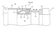
- FIG. 8 is an expanded longitudinal cross section of a seal assembly according to one non-limiting embodiment
- FIG. 9 is a general schematic view of an exemplary gas turbine engine with an exhaust duct according to another non-limiting embodiment
- FIG. 10 is a general schematic view of the exhaust duct of FIG. 9 in a first position.
- FIG. 11 is a general schematic view of the exhaust duct of FIG. 9 in a second position.
- FIG. 1 schematically illustrates a gas turbine engine 20 .
- the gas turbine engine 20 is disclosed herein as a two-spool low-bypass augmented turbofan that generally incorporates a fan section 22 , a compressor section 24 , a combustor section 26 , a turbine section 28 and an augmenter section 30 along a central longitudinal engine axis A.
- the gas turbine engine 20 is mounted to an exhaust duct section 32 and a nozzle section 34 (see also FIG. 2 ).
- variable cycle gas turbine engines power aircraft over a range of operating conditions and essentially alter a bypass ratio during flight to achieve countervailing objectives such as high specific thrust for high-energy maneuvers yet optimizes fuel efficiency for cruise and loiter operational modes.
- An outer structure 36 and an inner structure 38 define a generally annular secondary airflow path 40 around a core primary airflow path 42 .
- Various structure and modules may define the outer structure 36 and the inner structure 38 which essentially define an exoskeleton to support the rotational hardware therein.
- Air that enters the fan section 22 is divided between a primary airflow through the primary airflow path 42 and a secondary airflow through the secondary airflow path 40 .
- the primary airflow passes through the combustor section 26 , the turbine section 28 , then the augmentor section 30 where fuel may be selectively injected and burned to generate additional thrust through the nozzle section 34 .
- additional airflow streams such as third stream airflow typical of variable cycle engine architectures may additionally be sourced from the fan section 22 .
- the secondary airflow may be utilized for a multiple of purposes to include, for example, cooling and pressurization.
- the secondary airflow as defined herein is any airflow different from the primary airflow.
- the secondary airflow may ultimately be at least partially injected into the primary airflow path 42 adjacent to the exhaust duct section 32 and the nozzle section 34 .
- the exhaust duct section 32 may be circular in cross-section (see FIG. 3 ) as typical of an axis-symmetric augmented low bypass turbofan.
- the exhaust duct section 32 ′ may be non-axisymmetric in cross-section to include, but not be limited to, an oval cross-section (see FIG. 4 ) or a rectilinear cross-section (see FIG. 5 ).
- the exhaust duct section 32 ′ may be non-linear with respect to the central longitudinal engine axis A to form, for example, a serpentine shape to block direct view to the turbine section 28 (see FIG. 1 ).
- the nozzle section 34 may include, for example, a convergent/divergent nozzle, a non-axisymmetric two-dimensional (2D) vectorable nozzle, a flattened slot convergent nozzle of high aspect ratio or other geometry.
- the engine 20 may be embedded within and mounted to an airframe W (illustrated schematically in FIG. 7 ) remote from the nozzle section 34 which is also mounted to the airframe W.
- airframe W illustrated schematically in FIG. 7
- Such a direct mount arrangement requires that thermal growth be accommodated within the exhaust duct section 32 .
- a seal assembly 50 is mounted therein between a first exhaust duct section 52 and a second exhaust duct section 54 for each of the primary airflow in the primary airflow path 42 and the secondary airflow through the secondary airflow path 40 . It should be appreciated that although each seal assembly 50 is located at similar axial positions, other arrangements as well as additional seal assemblies for additional airflow streams such as third stream airflow typical of variable cycle engine architectures may alternatively or additionally provided.
- the adjacent exhaust duct sections 52 , 54 have, for example, relatively large axial displacements greater than about 0.5 (12.7 mm) inches and relatively large radial displacements greater than about 0.125 inches (6.4 mm) in a high temperature environment while requiring sealing between the primary airflow in the primary airflow path 42 and the secondary airflow through the secondary airflow path 40 which operate at differential pressures.
- each seal assembly 50 generally includes a channel 60 , a faying extension 62 and a tadpole seal 64 . It should be appreciated that various arrangements may alternatively or additionally be provided.
- the channel 60 is mounted to an aft section 66 of the first exhaust duct section 52 and extends downstream therefrom.
- the faying extension 62 is mounted to a forward section 68 of the second exhaust duct section 54 and extends upstream therefrom to at least partially extend into the channel 60 which contains the tadpole seal 64 .
- the tadpole seal 64 may include a silica cover wrapped around an Inconel mesh bulb core such as McMaster-Carr P/N 8853K13.
- the example tadpole seal 64 offers higher temperature resistance than fiberglass seals and the Inconel insert provides added strength.
- the example tadpole seal 64 resists contaminates and seals at temperatures up to about 1700° F.
- the tadpole seal 64 is readily cut to length, for example, via a laser which fuses end section edges thereof.
- the tadpole seal 64 may be installed as a strip or, alternatively, the end sections may be fused together to form a complete ring.
- the tadpole seal 64 generally includes a bulb 70 and a tail 72 .
- the tadpole seal 64 is located within the channel 60 with the tail 72 directed upstream in the channel 60 .
- the faying extension 62 engages the bulb 70 to provide the seal.
- the bulb 70 translates axially when compressed by the deflection/displacement of the faying extension 62 as the exhaust duct sections 52 , 54 grow toward each other under thermal expansion. That is, as the engine 20 and the nozzle section 34 are fixed to the airframe W (see FIG. 7 ), any thermal growth is accommodated within the seal assembly 50 as the exhaust duct sections 52 , 54 grow toward each other under thermal expansion.
- the tail 72 of the tadpole seal 64 essentially operates as a low rate spring to keep the primary sealing surface (e.g., the bulb 70 ) engaged. As the faying extension 62 deflects/displaces radially, contact is maintained with the bulb 70 .
- the tail 72 remains in contact with a backwall 74 of the channel 60 to maintain a secondary sealing surface. That is, the tail 72 may remain in contact with a backwall 74 of the channel 60 throughout the relative axial displacement between the exhaust duct sections 52 , 54 .
- the backwall 74 extends radially between a radial out wall 76 and a radial inner wall 78 which together form an open annulus directed axially aft.
- one or more ports 80 are located in the channel 60 upstream of the bulb 70 to provide pressure balance. That is, the ports 80 upstream of the bulb 70 permit the pressure from within the respective primary airflow path 42 and the secondary airflow path 40 to enter the channel 60 and effectively increase the preload provided by the tail 72 .
- an exhaust duct section 32 A in another disclosed non-limiting embodiment, includes a three-bearing swivel duct (3BSD) 90 (illustrated schematically) for use in a short take off vertical landing (STOVL) type of aircraft.
- the 3BSD 90 includes three exhaust ducts 92 , 94 , 96 which rotate relative to each other about three bearing planes 98 , 100 , 102 to permit transition between a cruise configuration (see FIG. 10 ) in which the 3BSD 90 is arranged along the central longitudinal engine axis A and a hover configuration (see FIG. 11 ) in which the 3BSD 90 articulates the nozzle section 34 A to a position transverse to the central longitudinal engine axis A.
- each of the three bearing planes 98 , 100 , 102 includes a respective seal assembly 50 as above described.
- Each seal assembly 50 operates to seal the 3BSD 90 yet permits relative rotation.
- the seal assembly 50 accommodates significant displacements, is relatively uncomplicated with machined or spun seal cavities and laser cut tadpole seals that advantageously reduces weight.
- the seal assembly 50 is readily applicable to complex geometries and is easily maintainable as the tadpole seal is fully contained at assembly and fully removable when parts are separated.
Landscapes
- Engineering & Computer Science (AREA)
- General Engineering & Computer Science (AREA)
- Mechanical Engineering (AREA)
- Chemical & Material Sciences (AREA)
- Combustion & Propulsion (AREA)
- Turbine Rotor Nozzle Sealing (AREA)
- Sealing Using Fluids, Sealing Without Contact, And Removal Of Oil (AREA)
- Laser Beam Processing (AREA)
Abstract
Description
Claims (14)
Priority Applications (1)
| Application Number | Priority Date | Filing Date | Title |
|---|---|---|---|
| US14/913,215 US10378451B2 (en) | 2013-09-13 | 2014-09-10 | Large displacement high temperature seal |
Applications Claiming Priority (3)
| Application Number | Priority Date | Filing Date | Title |
|---|---|---|---|
| US201361877665P | 2013-09-13 | 2013-09-13 | |
| US14/913,215 US10378451B2 (en) | 2013-09-13 | 2014-09-10 | Large displacement high temperature seal |
| PCT/US2014/054986 WO2015080779A2 (en) | 2013-09-13 | 2014-09-10 | Large displacement high temperature seal |
Publications (2)
| Publication Number | Publication Date |
|---|---|
| US20160201566A1 US20160201566A1 (en) | 2016-07-14 |
| US10378451B2 true US10378451B2 (en) | 2019-08-13 |
Family
ID=53199708
Family Applications (1)
| Application Number | Title | Priority Date | Filing Date |
|---|---|---|---|
| US14/913,215 Active 2036-02-04 US10378451B2 (en) | 2013-09-13 | 2014-09-10 | Large displacement high temperature seal |
Country Status (3)
| Country | Link |
|---|---|
| US (1) | US10378451B2 (en) |
| EP (1) | EP3044446B1 (en) |
| WO (2) | WO2015080779A2 (en) |
Families Citing this family (2)
| Publication number | Priority date | Publication date | Assignee | Title |
|---|---|---|---|---|
| US10562641B2 (en) * | 2012-10-10 | 2020-02-18 | Sikorsky Aircraft Corporation | AFT exhaust system for rotary wing aircraft |
| US10358940B2 (en) | 2017-06-26 | 2019-07-23 | United Technologies Corporation | Elliptical slot with shielding holes |
Citations (26)
| Publication number | Priority date | Publication date | Assignee | Title |
|---|---|---|---|---|
| US3020185A (en) | 1958-07-28 | 1962-02-06 | Connecticut Hard Rubber Co | Wire reinforced polytetrafluoroethylene seal |
| US3986687A (en) | 1975-06-30 | 1976-10-19 | General Electric Company | Aircraft propulsion system with flight maneuverable exhaust nozzle |
| US4132068A (en) | 1975-04-30 | 1979-01-02 | The United States Of America As Represented By The United States National Aeronautics And Space Administration | Variable area exhaust nozzle |
| US4441726A (en) | 1981-12-14 | 1984-04-10 | Shan-Rod, Inc. | Heat and vibration resistant seal |
| US4575099A (en) * | 1984-01-27 | 1986-03-11 | General Electric Company | High excursion seal with flexible membrane to prevent gas leakage through hinge |
| US5104286A (en) * | 1991-02-08 | 1992-04-14 | Westinghouse Electric Corp. | Recirculation seal for a gas turbine exhaust diffuser |
| US5251917A (en) * | 1987-06-22 | 1993-10-12 | The Boeing Company | Fire-resistant seal |
| US6170831B1 (en) | 1998-12-23 | 2001-01-09 | United Technologies Corporation | Axial brush seal for gas turbine engines |
| US6318668B1 (en) | 1996-08-02 | 2001-11-20 | Allison Advanced Development Company | Thrust vectoring techniques |
| US6352211B1 (en) | 2000-10-06 | 2002-03-05 | General Electric Company | Flow blocking exhaust nozzle |
| US6382559B1 (en) | 1999-08-13 | 2002-05-07 | Rolls-Royce Corporation | Thrust vectoring mechanism |
| US20050235630A1 (en) * | 2004-04-21 | 2005-10-27 | Cuva William J | High temperature dynamic seal for scramjet variable geometry |
| US20050242525A1 (en) | 2004-04-30 | 2005-11-03 | Stefan Dahlke | Hot gas seal |
| US20060277922A1 (en) | 2005-06-09 | 2006-12-14 | Pratt & Whitney Canada Corp. | Turbine support case and method of manufacturing |
| US20090127806A1 (en) * | 2007-11-15 | 2009-05-21 | Spirit Aerosystems, Inc. | Low-leakage seal system for pivot door type thrust reverser |
| US20090208326A1 (en) | 2006-09-08 | 2009-08-20 | Eric Durocher | Rim seal for a gas turbine engine |
| US20100199583A1 (en) | 2009-02-09 | 2010-08-12 | The Boeing Company | Tile gap seal assembly and method |
| US7818957B2 (en) | 2005-08-29 | 2010-10-26 | General Electric Company | Valve assembly for a gas turbine engine |
| US7861535B2 (en) | 2007-09-24 | 2011-01-04 | United Technologies Corporation | Self-aligning liner support hanger |
| US7966823B2 (en) | 2006-01-06 | 2011-06-28 | General Electric Company | Exhaust dust flow splitter system |
| US8015996B2 (en) | 2005-04-28 | 2011-09-13 | United Technologies Corporation | Gas turbine engine air valve assembly |
| US8205821B2 (en) | 2006-12-13 | 2012-06-26 | General Electric Company | Engine propulsion system and methods of assembling the same |
| US8317126B2 (en) | 2009-05-29 | 2012-11-27 | Rolls-Royce Plc | Aircraft having a lift/propulsion unit |
| US8360361B2 (en) | 2006-05-23 | 2013-01-29 | University Of Virginia Patent Foundation | Method and apparatus for jet blast deflection |
| US20130091864A1 (en) * | 2011-10-18 | 2013-04-18 | General Electric Company | Quick disengaging field joint for exhaust system components of gas turbine engines |
| US20140265161A1 (en) * | 2013-03-15 | 2014-09-18 | Rolls-Royce North American Technologies, Inc. | Seals for a gas turbine engine |
Family Cites Families (5)
| Publication number | Priority date | Publication date | Assignee | Title |
|---|---|---|---|---|
| US4828441A (en) * | 1987-07-08 | 1989-05-09 | United Technologies Corporation | Locked threaded insert for high stress application |
| US6681577B2 (en) * | 2002-01-16 | 2004-01-27 | General Electric Company | Method and apparatus for relieving stress in a combustion case in a gas turbine engine |
| GB0216362D0 (en) * | 2002-07-13 | 2002-08-21 | Rolls Royce Plc | Stress defender holes |
| GB2421582B (en) * | 2004-12-18 | 2007-02-28 | Rolls Royce Plc | A balancing method |
| US8888442B2 (en) * | 2012-01-30 | 2014-11-18 | Pratt & Whitney Canada Corp. | Stress relieving slots for turbine vane ring |
-
2014
- 2014-09-10 EP EP14866582.1A patent/EP3044446B1/en active Active
- 2014-09-10 US US14/913,215 patent/US10378451B2/en active Active
- 2014-09-10 WO PCT/US2014/054986 patent/WO2015080779A2/en not_active Ceased
- 2014-09-12 WO PCT/US2014/055439 patent/WO2015084450A2/en not_active Ceased
Patent Citations (26)
| Publication number | Priority date | Publication date | Assignee | Title |
|---|---|---|---|---|
| US3020185A (en) | 1958-07-28 | 1962-02-06 | Connecticut Hard Rubber Co | Wire reinforced polytetrafluoroethylene seal |
| US4132068A (en) | 1975-04-30 | 1979-01-02 | The United States Of America As Represented By The United States National Aeronautics And Space Administration | Variable area exhaust nozzle |
| US3986687A (en) | 1975-06-30 | 1976-10-19 | General Electric Company | Aircraft propulsion system with flight maneuverable exhaust nozzle |
| US4441726A (en) | 1981-12-14 | 1984-04-10 | Shan-Rod, Inc. | Heat and vibration resistant seal |
| US4575099A (en) * | 1984-01-27 | 1986-03-11 | General Electric Company | High excursion seal with flexible membrane to prevent gas leakage through hinge |
| US5251917A (en) * | 1987-06-22 | 1993-10-12 | The Boeing Company | Fire-resistant seal |
| US5104286A (en) * | 1991-02-08 | 1992-04-14 | Westinghouse Electric Corp. | Recirculation seal for a gas turbine exhaust diffuser |
| US6318668B1 (en) | 1996-08-02 | 2001-11-20 | Allison Advanced Development Company | Thrust vectoring techniques |
| US6170831B1 (en) | 1998-12-23 | 2001-01-09 | United Technologies Corporation | Axial brush seal for gas turbine engines |
| US6382559B1 (en) | 1999-08-13 | 2002-05-07 | Rolls-Royce Corporation | Thrust vectoring mechanism |
| US6352211B1 (en) | 2000-10-06 | 2002-03-05 | General Electric Company | Flow blocking exhaust nozzle |
| US20050235630A1 (en) * | 2004-04-21 | 2005-10-27 | Cuva William J | High temperature dynamic seal for scramjet variable geometry |
| US20050242525A1 (en) | 2004-04-30 | 2005-11-03 | Stefan Dahlke | Hot gas seal |
| US8015996B2 (en) | 2005-04-28 | 2011-09-13 | United Technologies Corporation | Gas turbine engine air valve assembly |
| US20060277922A1 (en) | 2005-06-09 | 2006-12-14 | Pratt & Whitney Canada Corp. | Turbine support case and method of manufacturing |
| US7818957B2 (en) | 2005-08-29 | 2010-10-26 | General Electric Company | Valve assembly for a gas turbine engine |
| US7966823B2 (en) | 2006-01-06 | 2011-06-28 | General Electric Company | Exhaust dust flow splitter system |
| US8360361B2 (en) | 2006-05-23 | 2013-01-29 | University Of Virginia Patent Foundation | Method and apparatus for jet blast deflection |
| US20090208326A1 (en) | 2006-09-08 | 2009-08-20 | Eric Durocher | Rim seal for a gas turbine engine |
| US8205821B2 (en) | 2006-12-13 | 2012-06-26 | General Electric Company | Engine propulsion system and methods of assembling the same |
| US7861535B2 (en) | 2007-09-24 | 2011-01-04 | United Technologies Corporation | Self-aligning liner support hanger |
| US20090127806A1 (en) * | 2007-11-15 | 2009-05-21 | Spirit Aerosystems, Inc. | Low-leakage seal system for pivot door type thrust reverser |
| US20100199583A1 (en) | 2009-02-09 | 2010-08-12 | The Boeing Company | Tile gap seal assembly and method |
| US8317126B2 (en) | 2009-05-29 | 2012-11-27 | Rolls-Royce Plc | Aircraft having a lift/propulsion unit |
| US20130091864A1 (en) * | 2011-10-18 | 2013-04-18 | General Electric Company | Quick disengaging field joint for exhaust system components of gas turbine engines |
| US20140265161A1 (en) * | 2013-03-15 | 2014-09-18 | Rolls-Royce North American Technologies, Inc. | Seals for a gas turbine engine |
Non-Patent Citations (1)
| Title |
|---|
| EP search report for EP14866582.1 dated Sep. 1, 2016. |
Also Published As
| Publication number | Publication date |
|---|---|
| US20160201566A1 (en) | 2016-07-14 |
| EP3044446B1 (en) | 2021-11-17 |
| WO2015084450A2 (en) | 2015-06-11 |
| WO2015080779A2 (en) | 2015-06-04 |
| WO2015084450A3 (en) | 2015-08-27 |
| EP3044446A2 (en) | 2016-07-20 |
| WO2015080779A3 (en) | 2015-08-13 |
| EP3044446A4 (en) | 2016-10-05 |
Similar Documents
| Publication | Publication Date | Title |
|---|---|---|
| US9915162B2 (en) | Flexible feather seal for blade outer air seal gas turbine engine rapid response clearance control system | |
| US10247028B2 (en) | Gas turbine engine blade outer air seal thermal control system | |
| US10316683B2 (en) | Gas turbine engine blade outer air seal thermal control system | |
| US10370999B2 (en) | Gas turbine engine rapid response clearance control system with air seal segment interface | |
| US10047629B2 (en) | Multi-segment adjustable stator vane for a variable area vane arrangement | |
| US10132193B2 (en) | Gas turbine engine duct assembly | |
| US10151217B2 (en) | Turbine frame cooling systems and methods of assembly for use in a gas turbine engine | |
| US10060286B2 (en) | Geared annular airflow actuation system for variable cycle gas turbine engines | |
| EP3026228B1 (en) | Gas turbine engine clearance control | |
| US10036263B2 (en) | Stator assembly with pad interface for a gas turbine engine | |
| US20160290150A1 (en) | Seals for gas turbine engine | |
| EP3093442B1 (en) | Vane strut positioning and securing systems | |
| US10378451B2 (en) | Large displacement high temperature seal | |
| US10570767B2 (en) | Gas turbine engine with a cooling fluid path | |
| US9915228B2 (en) | Air with integral spring for a gas turbine engine exhaust drive | |
| US20180051571A1 (en) | Airfoil for a turbine engine with porous rib | |
| EP3075952B1 (en) | Retaining rings for turbomachine disk and coverplate assemblies | |
| EP3044442B1 (en) | Ceramic liner for a turbine exhaust case |
Legal Events
| Date | Code | Title | Description |
|---|---|---|---|
| AS | Assignment |
Owner name: UNITED TECHNOLOGIES CORPORATION, CONNECTICUT Free format text: ASSIGNMENT OF ASSIGNORS INTEREST;ASSIGNOR:DILLARD, GARY J.;REEL/FRAME:037779/0078 Effective date: 20130912 |
|
| STPP | Information on status: patent application and granting procedure in general |
Free format text: NOTICE OF ALLOWANCE MAILED -- APPLICATION RECEIVED IN OFFICE OF PUBLICATIONS |
|
| STCF | Information on status: patent grant |
Free format text: PATENTED CASE |
|
| AS | Assignment |
Owner name: RAYTHEON TECHNOLOGIES CORPORATION, MASSACHUSETTS Free format text: CHANGE OF NAME;ASSIGNOR:UNITED TECHNOLOGIES CORPORATION;REEL/FRAME:054062/0001 Effective date: 20200403 |
|
| AS | Assignment |
Owner name: RAYTHEON TECHNOLOGIES CORPORATION, CONNECTICUT Free format text: CORRECTIVE ASSIGNMENT TO CORRECT THE AND REMOVE PATENT APPLICATION NUMBER 11886281 AND ADD PATENT APPLICATION NUMBER 14846874. TO CORRECT THE RECEIVING PARTY ADDRESS PREVIOUSLY RECORDED AT REEL: 054062 FRAME: 0001. ASSIGNOR(S) HEREBY CONFIRMS THE CHANGE OF ADDRESS;ASSIGNOR:UNITED TECHNOLOGIES CORPORATION;REEL/FRAME:055659/0001 Effective date: 20200403 |
|
| MAFP | Maintenance fee payment |
Free format text: PAYMENT OF MAINTENANCE FEE, 4TH YEAR, LARGE ENTITY (ORIGINAL EVENT CODE: M1551); ENTITY STATUS OF PATENT OWNER: LARGE ENTITY Year of fee payment: 4 |
|
| AS | Assignment |
Owner name: RTX CORPORATION, CONNECTICUT Free format text: CHANGE OF NAME;ASSIGNOR:RAYTHEON TECHNOLOGIES CORPORATION;REEL/FRAME:064714/0001 Effective date: 20230714 |