US10377494B2 - Aircraft divider assembly - Google Patents
Aircraft divider assembly Download PDFInfo
- Publication number
- US10377494B2 US10377494B2 US15/441,051 US201715441051A US10377494B2 US 10377494 B2 US10377494 B2 US 10377494B2 US 201715441051 A US201715441051 A US 201715441051A US 10377494 B2 US10377494 B2 US 10377494B2
- Authority
- US
- United States
- Prior art keywords
- divider assembly
- removable panel
- panel
- upper section
- main body
- Prior art date
- Legal status (The legal status is an assumption and is not a legal conclusion. Google has not performed a legal analysis and makes no representation as to the accuracy of the status listed.)
- Active, expires
Links
Images


Classifications
-
- B—PERFORMING OPERATIONS; TRANSPORTING
- B64—AIRCRAFT; AVIATION; COSMONAUTICS
- B64D—EQUIPMENT FOR FITTING IN OR TO AIRCRAFT; FLIGHT SUITS; PARACHUTES; ARRANGEMENT OR MOUNTING OF POWER PLANTS OR PROPULSION TRANSMISSIONS IN AIRCRAFT
- B64D11/00—Passenger or crew accommodation; Flight-deck installations not otherwise provided for
- B64D11/0023—Movable or removable cabin dividers, e.g. for class separation
Definitions
- the present invention relates to an aircraft divider assembly, and more particularly to an aircraft class divider that includes a removable panel.
- the different seating classes are often separated by a class divider.
- the entire divider typically, the entire divider as to be replaced with a new one.
- the present invention provides the ability to change portions of the class divider without having to remove the entire assembly.
- a divider assembly that includes a main body portion having a lower section and an upper section and a removable panel having front and back surfaces.
- the upper section tapers in width in an upward direction and the main body portion includes front and back surfaces.
- the removable panel is removably secured to the upper section on the front surface of the main body portion.
- the upper section includes an opening therethrough that is defined by a border portion and the removable panel spans the opening. The back surface of the removable panel is in contact with the border portion.
- the upper section has a narrower thickness dimension than the lower section, and the thickness of the upper section and the removable panel is the same or less than the thickness of the lower section.
- a ledge is defined on the front surface of the main body portion by the thicker lower section.
- a gap is defined between a bottom surface of the removable panel and the ledge.
- a removable cover strip is positioned to cover the gap.
- a bottom portion of the removable panel is removably secured to the upper section by fastening means.
- the cover strip is positioned using a French cleat.
- the cover strip includes a hook portion that is engaged with the top of the French cleat.
- a lighted panel is positioned behind the cover strip.
- a channel is defined at least partially around the upper section.
- the channel receives at least a portion of the outer edge of the removable panel.
- the upper section further includes a trim extending at least partially therearound. The trim defines the channel that receives the outer edge of the removable panel.
- the divider assembly further includes at least one of a literature pocket module, in-flight entertainment module, cup holder module, coat hook module, tablet holder module or panel module removably secured to the back surface of the main body portion.
- the present invention is an aircraft partition that includes a removable or changeable upper panel.
- the main body portion of the partition includes a trim that extends around the edges and that is preferably made of aluminum or other metal.
- the trim can be made of plastic or the like.
- the aluminum profile wraps around the whole perimeter of the panel and has a U-shape that captures the top and side edges of the upper panel.
- the partition is tapered towards the top (i.e., it is wider at the bottom than it is at the top when viewed from a fore or aft position in an aircraft). Therefore, by sliding the panel down a predetermined distance (e.g., one inch), it clears the trim on either side and can be removed.
- the partition also includes fixings along the bottom of the panel to stop the panel from dropping down during regular use.
- the panel has a mechanical fixing at the bottom thereof to hold it in position, but it is supported structurally around its perimeter edge (top and side edges) by the U-shaped aluminum extrusion or trim.
- the panel is essentially a wedge that is being slid up into the space or channel created by the trim.
- the smaller dimension panel e.g., eighth of an inch
- the panel can be used to bring the whole panel back up to an inch again so that it is a generally constant thickness all the way through.
- a trim or narrow panel covers the gap between the upper panel and the lower section or panel. This gap is provided to allow the upper panel to move or slide downwardly so that it clears the trim and can be removed.
- the narrow upper panel is secured in place by a French cleat, which has a ledge across its top edge and then has fixings at the bottom (e.g., threaded fasteners, Velcro, screws, slide fittings or the like to lock it in place).
- the present invention provides airlines or other users with the ability to quickly and easily reconfigure cabin décor panels on aircraft partitions.
- the system uses crushed panel technology in combination with a capturing edge trim frame that allows a décor panel (upper panel or section) to be slid into position and secured or locked with mechanical fasteners.
- panels or sections on other cabin vertical surfaces e.g., galleys, stowages and lavatories
- the divider assembly can be a full height partition or less than full height.
- the bottom portion and the upper portion comprise honeycomb panels (or a single honeycomb panel) and the upper section (or removable panel) is removable therefrom.
- the upper panel has a thinner dimension than the lower section. This allows the removable panel to bring the overall dimension of the upper portion of the partition to be about the same as the lower section. Therefore, the upper portion is also referred to herein as the indented portion.
- the removable panel can be an opaque panel that can include branding thereon or a direct view panel, which is transparent or see-through.
- the divider assembly includes an outer trim or rim that is U-shaped and retains the removable panel on the top and sides of the removable panel and a forward facing trim or cover panel that conceals the bottom edge of the removable panel and the gap between the removable panel and a lower portion.
- the divider assembly (specifically, the upper portion) includes an opening defined therethrough so that a passenger can see through the partition when a direct view panel is used. In another embodiment, the opening can be omitted.
- the trim defines a channel that captures or retains the top and side edges of the removable panel.
- the divider assembly includes means for attaching the cover panel to the upper portion.
- the attachment means is a French cleat that is secured to the main body portion by threaded fasteners or the like.
- the French cleat is used to locate and support the cover panel.
- the cover panel overlaps the entire strip of the French cleat for location and support and is then secured in place with mechanical fasteners.
- the French cleat can have Velcro, adhesive, tape, glue or the like on the front surface thereof so that the cover panel can be attached thereto.
- the French cleat can be omitted and the cover panel can be directly connected to the upper portion.
- the removable panel is secured at the bottom thereof to the indented portion. This can be done by threaded fasteners, such as screws, by snaps, buttons, Velcro or other securing device that allows the removable panel to be unattached to the upper portion.
- threaded fasteners such as screws
- snaps buttons
- Velcro Velcro
- the removable panel and the upper portion include openings therein for receiving threaded fasteners.
- the divider assembly includes branding associated with the cover panel.
- a lighted element that says “ecos” is secured to the main body portion.
- the cover panel includes “ecos” thereon that can be back lit by the lighted element. “Ecos” is only exemplary. Any logo, word, picture, inscription can be included.
- the removable panel can include a cutout therein for routing the wiring associated with the lighted element.
- Step one includes removing the cover panel from the divider assembly. There is a gap between the bottom edge of the removable panel and the top edge of the lower portion. This gap allows the removable panel to move downwardly.
- Step two includes lowering the removable panel (and closing the gap) until the bottom edge of the removable panel contacts the top edge of the lower portion.
- the removable panel can just be lowered without having to contact the top edge of the lower section.
- Step three includes continuing to lower the removable panel by pulling forward and slightly away from the lower section so that the bottom edge of the removable panel clears the top edge of the lower section. Next, the removable panel can be removed and is now completely free of the partition.
- the main body portion of the divider assembly includes a downwardly extending foot that attaches to the seat tracks in the floor of the cabin.
- the foot spaces the bottom of the main body portion from the floor to provide room for passengers' feet.
- the main body portion also includes an upwardly extending connector for connecting to the ceiling or wall of the cabin.
- a connector can also extend from the side of the main body portion.
- the divider assembly can include outlets or ports (e.g., USB) for providing electrical and/or data communication with personal devices, such as tablets, phones or other computer devices.
- the upper panel can include LED lighting therearound or therein to emphasize any branding thereon.
- the partition is customizable and modular. Customizable means that the partition can be customized depending on the customer's (e.g., airline's) desires. Also, it is preferably modular, meaning that the cover panels can be changed or switched out when they are worn out, dirty or to update the look of the aircraft. Different materials or looks or branding can be included on the different cover panels. Airlines are then able to change the cabin atmosphere without changing the entire divider assembly. Therefore, it should be understood that the partition shown in the attached drawings and described herein is only exemplary and that many changes and customizations can be made to the invention.
- TV screens can be built into or attached to the partition.
- the removable cover panel or module on at least one of the sections can include literature pockets thereon.
- the modules can include a literature pocket module, a passenger accessories module (e.g., phone, USB, tablet holder), a crew accessories module or an in-flight entertainment module, etc.
- FIG. 1 is a perspective view of a divider assembly position in an aircraft cabin in accordance with a preferred embodiment of the present invention
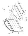
- FIG. 2 is an exploded perspective view of the divider assembly of FIG. 1 ;
- FIG. 3 is a front elevational view of the divider assembly of FIG. 1 ;
- FIG. 4 is a cross-sectional view of the divider assembly of FIG. 1 ;
- FIG. 4A is a cross-sectional view of a portion of FIG. 4 ;
- FIG. 4B is a cross-sectional view similar to FIG. 4A , but with the panel exploded therefrom;
- FIG. 4C is a cross-sectional view of another portion of FIG. 4 ;
- FIG. 4D is a cross-sectional view similar to FIG. 4C , but with some components exploded therefrom;
- FIGS. 5A-5E are a series of perspective views showing exemplary steps for removing the panel from the divider assembly
- FIG. 6 is a perspective view of the aft side of the divider assembly.
- FIG. 7 is an exploded perspective view of the aft side of the divider assembly.
- references in this specification to “one embodiment” or “an embodiment” means that a particular feature, structure, or characteristic described in connection with the embodiment is included in at least one embodiment of the-disclosure.
- the appearances of the phrase “in one embodiment” in various places in the specification are not necessarily all referring to the same embodiment, nor are separate or alternative embodiments mutually exclusive of other embodiments.
- various features are described which may be exhibited by some embodiments and not by others.
- various requirements are described which may be requirements for some embodiments but not other embodiments.
- the divider assembly 10 is positionable between rows of seats 100 or other components (lavatories, closets, galleys, etc.) in an aircraft cabin 102 to divide sections or classes of the aircraft.
- the divider assembly 10 can be positioned or mounted between first and coach classes.
- FIG. 1 shows the divider assembly 10 mounted in the interior of an aircraft.
- the divider assembly 10 generally includes a main body portion 12 having front and back surfaces 12 a and 12 b , a lower section 14 and an upper section 16 .
- the upper section 16 tapers in width in an upward direction (towards the ceiling of the aircraft).
- the upper section 16 defines a bottom width W 1 and a top width W 2 and the top width W 2 is narrower than the bottom width W 1 .
- the divider assembly 10 generally includes the main body portion 12 , a removable panel 18 having front and back surfaces 18 a and 18 b , a cover strip 20 , a French cleat 22 and a light assembly or lighted panel 24 .
- the removable panel 18 is removably secured to the upper section 16 on the front surface 12 a of the main body portion 12 .
- the removable panel can be secured to the back surface 12 b of the main body portion 12 or to either side of the lower section.
- the upper section 16 has a narrower thickness dimension than the lower section 14 . This allows the removable panel 18 to be secured to the upper section 16 without increasing the overall thickness of the main body portion 12 .
- the thickness of the upper section 16 and the removable panel 18 together is the same or less than the thickness of the lower section 14 .
- the upper section is also referred to herein as the indented section or portion.
- a ledge 26 is defined on the front surface 12 a of the main body portion 12 by the thicker lower section 14 . The ledge 26 spans the width of the main body portion 12 . In another embodiment, the ledge may only span a portion of the width of the main body portion 12 .
- the removable panel 18 can be opaque or transparent/see-through.
- the upper section 16 includes an opening 28 therethrough that is defined by a border portion 30 .
- a frame 31 can also be included to help define opening 28 and for aesthetic purposes.
- the border portion 30 is essentially the solid portion of the upper section 16 .
- the removable panel 18 spans the opening 28 and the back surface 18 b of the removable panel 18 is secured against or in contact with the border portion 30 .
- the bottom portion of the removable panel 18 is removably secured to the upper section by fastening means.
- fastening means Any method for securing the removable panel 18 to the upper section 16 (or any section of the main body portion 12 ) is within the scope of the present invention.
- threaded fasteners 32 are secured through holes in the removable panel 18 and are threaded into holes in the main body portion 12 .
- the fastening means can be non-threaded fasteners, rivets, adhesive, glue, tape, welding or the like. It will be appreciated that the fastening means can also be used to secure the sides and/or the top of the removable panel 18 .
- the side and top edges 18 d and 18 e of the removable panel 18 are received in and secured by a channel 34 that is defined by trim 36 that extends around the outside of the upper section 16 or the entire main body portion 12 .
- Channel 34 can be defined by components other than trim.
- the channel can be defined directly in the main body portion 12 or include a component inboard of the trim.
- a gap 38 is defined between the bottom edge 18 c of the removable panel and the ledge 26 .
- This gap 38 allows the removable panel 18 to move downwardly when being removed, as further described below.
- the cover strip 20 is positioned to cover the gap 38 (and the threaded fasteners 32 ).
- the cover strip 20 is secured in place by the French cleat 22 .
- the French cleat 22 is secured to the main body portion 12 and/or the upper section 16 by fasteners, threaded fasteners, adhesive, glue, tape, welding, quick release fasteners, spring biased clips or other attachment method.
- the cover strip 20 is secured to the front surface of the French cleat 22 by the Velcro, tape, adhesive, threaded fasteners or the like. As shown in FIGS. 4C and 4D , the cover strip 20 can also include a hook portion 40 on the top thereof that hooks over the top edge of the French cleat 22 to help secure the cover strip 20 in place. In another embodiment, the French cleat can be omitted and the cover strip 20 can be directly connected to the main body portion 12 and/or the upper section 16 or the removable panel 18 . The French cleat 22 can also be used to hold or secure the bottom of the removable panel 18 . As shown in FIG. 4C , the French cleat defines a trough 42 that receives the bottom portion of the removable panel 18 .
- the French cleat 22 can be omitted, the threaded fasteners 32 securing the bottom of the removable panel 18 can be omitted, and the cover strip 20 can be used to secure the bottom of the removable panel 18 in place.
- the cover strip 20 can be used to secure the bottom of the removable panel 18 in place.
- the divider assembly 10 includes upper and lower attachment portions 44 and 46 for securing the divider assembly 10 to the floor of the aircraft cabin and/or the ceiling or any component above the main body portion 10 .
- the lower attachment portions 44 can be spaced such that they attached to the seat attachment tracks on the floor of the aircraft cabin 102 and the upper attachment portion 46 can include posts that extend upwardly and attached to the personal service unit rails associated with the overhead storage bins.
- the removable panel 18 can include a cutout 18 f defined therein that surrounds or makes room for the upper attachment portion 46 .
- the divider somewhere 10 includes the lighted panel 24 positioned behind the cover strip 20 .
- the cover strip 20 includes inscribed writing, a transparent portion or other indicia 48 that is backlit by the lighted panel 24 .
- the removable panel 18 can include a cutout 18 g therein that receives the lighted panel 24 and allows wiring to be routed therethrough.
- the lighted panel 24 and indicia 48 on the cover strip 20 can be used for advertising purposes.
- FIGS. 5A-5E show exemplary steps for the removal of removable panel 18 from the divider assembly 10 .
- the cover strip 20 is removed from the French cleat 22 (or main body portion 12 if it is connected directly thereto).
- the French cleat 22 is removed from the main body portion 12 .
- the removable panel 18 is moved downwardly, thereby closing the gap 38 , until the bottom edge 18 c is close to or in contact with ledge 26 . When this happens the side and top edges of the removable panel 18 move partially or all the way out of the channel 34 .
- FIG. 5A the cover strip 20 is removed from the French cleat 22 (or main body portion 12 if it is connected directly thereto).
- the French cleat 22 is removed from the main body portion 12 .
- the removable panel 18 is moved downwardly, thereby closing the gap 38 , until the bottom edge 18 c is close to or in contact with ledge 26 . When this happens the side and top edges of the removable panel 18 move partially or all the way out of the channel 34 .
- the bottom of the removable panel 18 is pulled outwardly so that it clears the ledge 28 and the entire removable panel 18 is moved downwardly so that the side and top edges of the removable panel 18 clear the channel.
- the removable panel 18 is removed from the main body portion 12 of the divider assembly 10 . It will be appreciated that these steps can be changed. For example, in an embodiment where the cover strip holds the bottom of the removable panel in place, the step shown in FIG. 5B can be omitted.
- FIGS. 6-7 show an embodiment of the divider assembly 10 that includes modules on the back or aft side. It will be appreciated that the modules described herein are optional. In another embodiment, the divider assembly can include the modules and no removable panel.
- FIGS. 6 and 7 show an inflight-entertainment (“IFE”) module 50 a plurality of literature pocket modules 52 , a cup holder module 54 , a coat hook module 56 , a tablet holder module 58 , and a panel module 60 (only shown in FIG. 7 ). It will be appreciated that the term module is used herein to indicate that the modules can be removed and replaced with different or other modules. The various modules can be used by occupants of the seats on the back or aft side of the divider assembly 10 .
- IFE inflight-entertainment
- each of the literature pocket modules 52 can be removed separately.
- the literature pocket modules 52 can be part of a single panel and removed together.
- the main body portion 12 includes a crush or indentation 62 therein (or a separate indentation for each module).
- Male connectors are attached to the back of the literature pocket modules 52 and mate with openings 64 in positioned in the indentation 62 .
- the embodiment shown in the drawings includes three openings on the right and three opening on the left for each literature pocket module 52 .
- the male connectors can be positioned in the indentation and the openings can be in the back of the modules. Any connection methodology is within the scope of the present invention.
- connection can be made via mechanical fixings, press stubs, snap fit, friction fit, threaded fasteners, Velcro, adhesives, quick release fasteners, etc. Any of the modules discussed herein can be secured in place using any of the described attachment methods or others known to those of skill in the art.
- the literature pocket modules 52 can be replaced with other modules.
- a panel module 60 e.g., aesthetically pleasing wood paneling
- the cup holder module 54 , coat hook module 56 and tablet holder module 58 can be disposed in openings 66 defined in the main body portion 12 and secured in place with threaded fasteners or the like. In another preferred embodiment, the cup holder module 54 , coat hook module 56 and tablet holder module 58 can be disposed at the bottom of the IFE panel 50 and secured in place with mechanical fasteners or the like (to the IFE panel or the main body portion 12 ). Each of these modules can include a flange 68 for alignment and attachment purposes.
- the tablet holder module 58 can include a port (e.g., a USB port) therein. The modules can be permanently attached to the main body portion 12 or can be removable.
- the cup holder module 54 , coat hook module 56 and tablet holder module 58 or any combination thereof can be mounted or part of an accessories rail that spans most of the main body portion 12 .
- the accessories rail can be secured to the main body portion or be attached to the IFE module (e.g., the backplate 70 ).
- the individual modules 54 , 56 and 58 can be secured to the IFE module, the main body portion 12 , the monitor frame 50 , the rail or the branding strip 20 .
- the IFE module 50 includes a frame or backplate 70 having three monitor openings 72 defined therein for receiving monitors 74 (e.g., a honeycomb panel with three openings defined therein).
- the IFE module 50 includes a frame including two end caps one at the left and one at the right and two extrusions one at the top and one at the bottom. The bottom extrusion of the backplate 70 can be used as the accessories rail.
- the individual modules 54 , 56 and 58 are be secured to the back of the backplate or frame 70 .
- indentations or the like are defined in the back of the frame 70 and the flanges 68 of the modules 54 , 56 and/or 58 are received in the indentations and attached to the back of the frame.
- the backplate 70 can be connected to the main body portion 12 by any attachment method described herein. In a preferred embodiment, it is secured by one or more French cleats 22 .
- the monitors 74 can be secured to the backplate 70 or secured directly to the main body portion 12 (see openings 76 ). Wire openings 78 can also be included in the main body portion 12 for routing of wires to the monitors 74 .
- the accessories can be permanent or interchangeable. Their position on the rail can be adjustable. Furthermore, it should be understood that the accessories are not limited to cup/shelf/hook, but can include any mix of accessories. In an embodiment, any one or all of the accessories can be foldable or hingeable.
- the monitor panel 50 can be modular in construction, have a configurable width (to fit different panels) and/or can be monitor configurable (CNC hole size and position).
- the words “comprise,” “comprising,” and the like are to be construed in an inclusive sense, as opposed to an exclusive or exhaustive sense; that is to say, in the sense of “including, but not limited to.”
- the terms “connected,” “coupled,” or any variant thereof means any connection or coupling, either direct or indirect, between two or more elements; the coupling of connection between the elements can be physical, logical, or a combination thereof.
- the words “herein,” “above,” “below,” and words of similar import when used in this application, shall refer to this application as a whole and not to any particular portions of this application.
Landscapes
- Engineering & Computer Science (AREA)
- Aviation & Aerospace Engineering (AREA)
- Casings For Electric Apparatus (AREA)
- Connection Of Plates (AREA)
Abstract
Description
Claims (14)
Priority Applications (4)
| Application Number | Priority Date | Filing Date | Title |
|---|---|---|---|
| US15/441,051 US10377494B2 (en) | 2017-01-12 | 2017-02-23 | Aircraft divider assembly |
| EP17891258.0A EP3568352A4 (en) | 2017-01-12 | 2017-10-25 | Aircraft divider assembly |
| CA3044815A CA3044815C (en) | 2017-01-12 | 2017-10-25 | Aircraft divider assembly |
| PCT/US2017/058345 WO2018132147A1 (en) | 2017-01-12 | 2017-10-25 | Aircraft divider assembly |
Applications Claiming Priority (2)
| Application Number | Priority Date | Filing Date | Title |
|---|---|---|---|
| US201762445650P | 2017-01-12 | 2017-01-12 | |
| US15/441,051 US10377494B2 (en) | 2017-01-12 | 2017-02-23 | Aircraft divider assembly |
Publications (2)
| Publication Number | Publication Date |
|---|---|
| US20180194471A1 US20180194471A1 (en) | 2018-07-12 |
| US10377494B2 true US10377494B2 (en) | 2019-08-13 |
Family
ID=62782238
Family Applications (1)
| Application Number | Title | Priority Date | Filing Date |
|---|---|---|---|
| US15/441,051 Active 2038-04-01 US10377494B2 (en) | 2017-01-12 | 2017-02-23 | Aircraft divider assembly |
Country Status (4)
| Country | Link |
|---|---|
| US (1) | US10377494B2 (en) |
| EP (1) | EP3568352A4 (en) |
| CA (1) | CA3044815C (en) |
| WO (1) | WO2018132147A1 (en) |
Cited By (2)
| Publication number | Priority date | Publication date | Assignee | Title |
|---|---|---|---|---|
| US11230380B2 (en) * | 2018-01-16 | 2022-01-25 | The Boeing Company | Interior aircraft frame assembly for furnishings |
| US11407195B2 (en) * | 2017-08-22 | 2022-08-09 | The Boeing Company | Reusable covering for protecting a finished surface |
Families Citing this family (22)
| Publication number | Priority date | Publication date | Assignee | Title |
|---|---|---|---|---|
| US10556685B2 (en) * | 2017-05-30 | 2020-02-11 | The Boeing Company | Header assembly and method therefore |
| US10230257B1 (en) | 2017-09-12 | 2019-03-12 | Video Gaming Technologies, Inc. | Electronic gaming machine including a wireless charging apparatus |
| DE102018120609A1 (en) * | 2018-08-23 | 2020-02-27 | Airbus Operations Gmbh | Separating device and method for installing a separating device in a passenger cabin |
| AU2019240623A1 (en) | 2018-10-05 | 2020-04-23 | Aristocrat Technologies Australia Pty Limited | System and method for managing digital wallets |
| US11847885B2 (en) | 2018-10-05 | 2023-12-19 | Aristocrt Technologies Australia Pty Limited | System and method for cashless exchange at smart tables |
| US11037396B2 (en) | 2018-10-05 | 2021-06-15 | Aristocrat Technologies Australia Pty Limited | System and method for cardless connection at smart tables |
| US11972659B2 (en) | 2018-10-05 | 2024-04-30 | Aristocrat Technologies, Inc. | System and method for changing beacon identifiers for secure mobile communications |
| US11488441B2 (en) | 2018-10-05 | 2022-11-01 | Aristocrat Technologies, Inc. | System and method for changing beacon identifiers for secure mobile communications |
| US11034452B2 (en) * | 2018-10-29 | 2021-06-15 | Safran Cabin Inc. | Aircraft with staggered seating arrangement |
| US10919631B2 (en) * | 2018-10-29 | 2021-02-16 | Safran Cabin Inc. | Aircraft with multiple doors and multiple zones |
| US10661879B2 (en) * | 2018-10-29 | 2020-05-26 | Safran Cabin Inc. | Aircraft with selective cargo area access |
| CN113165744B (en) | 2018-10-31 | 2024-10-25 | 赛峰座椅美国有限责任公司 | Extended display integration for passenger seats |
| US11227466B2 (en) | 2019-08-30 | 2022-01-18 | Aristocrat Technologies, Inc. | Multi-currency digital wallets and gaming architectures |
| US20210078709A1 (en) * | 2019-09-18 | 2021-03-18 | Safran Cabin Inc. | Aircraft interior with removable panels |
| US20210078707A1 (en) * | 2019-09-18 | 2021-03-18 | Safran Cabin Inc. | Aircraft with configurable divider system |
| US20210078703A1 (en) * | 2019-09-18 | 2021-03-18 | Safran Cabin Inc. | Aircraft interior with modular panels |
| US11544994B2 (en) | 2020-03-27 | 2023-01-03 | Aristocrat Technologies, Inc. | Beacon to patron communications for electronic gaming devices |
| US11276271B2 (en) | 2020-04-03 | 2022-03-15 | Aristocrat Technologies, Inc. | Systems and methods for securely connecting an electronic gaming machine to an end user device |
| US12208171B2 (en) | 2020-04-30 | 2025-01-28 | Aristocrat Technologies, Inc. | Ultraviolet disinfection and sanitizing systems and methods for electronic gaming devices and other gaming equipment |
| US11926420B2 (en) | 2020-05-08 | 2024-03-12 | B/E Aerospace, Inc. | Aircraft cabin partition system |
| USD968513S1 (en) * | 2020-05-15 | 2022-11-01 | Aristocrat Technologies, Inc. (ATI) | Gaming machine divider |
| FR3128202A1 (en) * | 2021-10-20 | 2023-04-21 | Safran Seats | REMOVABLE HOLDING DEVICE FOR AN INSULATION CURTAIN FOR THE CREATION OF A REST SPACE INSIDE AN AIRCRAFT CABIN |
Citations (19)
| Publication number | Priority date | Publication date | Assignee | Title |
|---|---|---|---|---|
| US5024398A (en) | 1989-06-28 | 1991-06-18 | The Boeing Company | Office module for passenger aircraft |
| EP0629547A1 (en) | 1993-06-15 | 1994-12-21 | DaimlerChrysler Aerospace Airbus Gesellschaft mit beschränkter Haftung | Partition device |
| US5482230A (en) * | 1993-06-25 | 1996-01-09 | B E Aerospace, Inc. | Vehicle bulkhead safety system |
| US5957407A (en) | 1996-08-14 | 1999-09-28 | The Boeing Company | Convertible seat systems for wide body aircraft |
| US6152400A (en) | 1997-09-10 | 2000-11-28 | The Boeing Company | Aircraft lower lobe sleeping compartment |
| WO2002028712A1 (en) | 2000-10-03 | 2002-04-11 | Virgin Atlantic Airways Ltd. | An accommodation unit for a passenger vehicle |
| US20030062449A1 (en) | 2001-10-02 | 2003-04-03 | Sankrithi Mithra M.K.V. | Twin aisle small airplane |
| US6676079B2 (en) | 2001-10-01 | 2004-01-13 | Yoshihito Takeshima | Passenger aircraft |
| US6857598B2 (en) | 2002-10-10 | 2005-02-22 | The Boeing Company | Integrated high-speed aircraft and associated methods of manufacture |
| US20070034742A1 (en) | 2005-07-29 | 2007-02-15 | Mark Jaeger | Passenger compartment |
| US20090200422A1 (en) | 2008-02-11 | 2009-08-13 | Be Aerospace, Inc. | Class divider for aircraft cabin |
| US20110233333A1 (en) | 2009-12-14 | 2011-09-29 | Be Intellectual Property, Inc | Small diameter pressure structure commercial aircraft crew rest |
| US20130105627A1 (en) | 2011-11-01 | 2013-05-02 | C&D Zodiac, Inc. | High privacy passenger aircraft cabin arrangement |
| US20130248655A1 (en) * | 2012-03-22 | 2013-09-26 | B/E Aerospace, Inc. | Aircraft passenger suite seating arrangement |
| US20130321715A1 (en) | 2011-02-17 | 2013-12-05 | Millson Custom Solutions Inc. | Mounting apparatus for an audio/video system and related methods and systems |
| US20140175219A1 (en) * | 2012-12-11 | 2014-06-26 | C&D Zodiac, Inc. | Fixed aircraft aisle partition with lighting |
| US20150284084A1 (en) | 2014-04-04 | 2015-10-08 | Airbus Operations Gmbh | Foldable divider device for an aircraft cabin |
| US20160304204A1 (en) * | 2015-04-14 | 2016-10-20 | B/E Aerospace, Inc. | Modular aircraft closet |
| US20170283061A1 (en) * | 2016-04-04 | 2017-10-05 | B/E Aerospace, Inc. | Contoured class divider |
Family Cites Families (1)
| Publication number | Priority date | Publication date | Assignee | Title |
|---|---|---|---|---|
| US7358929B2 (en) * | 2001-09-17 | 2008-04-15 | Philips Solid-State Lighting Solutions, Inc. | Tile lighting methods and systems |
-
2017
- 2017-02-23 US US15/441,051 patent/US10377494B2/en active Active
- 2017-10-25 EP EP17891258.0A patent/EP3568352A4/en not_active Withdrawn
- 2017-10-25 CA CA3044815A patent/CA3044815C/en not_active Expired - Fee Related
- 2017-10-25 WO PCT/US2017/058345 patent/WO2018132147A1/en not_active Ceased
Patent Citations (22)
| Publication number | Priority date | Publication date | Assignee | Title |
|---|---|---|---|---|
| US5024398A (en) | 1989-06-28 | 1991-06-18 | The Boeing Company | Office module for passenger aircraft |
| EP0629547A1 (en) | 1993-06-15 | 1994-12-21 | DaimlerChrysler Aerospace Airbus Gesellschaft mit beschränkter Haftung | Partition device |
| US5482230A (en) * | 1993-06-25 | 1996-01-09 | B E Aerospace, Inc. | Vehicle bulkhead safety system |
| US5957407A (en) | 1996-08-14 | 1999-09-28 | The Boeing Company | Convertible seat systems for wide body aircraft |
| US6152400A (en) | 1997-09-10 | 2000-11-28 | The Boeing Company | Aircraft lower lobe sleeping compartment |
| WO2002028712A1 (en) | 2000-10-03 | 2002-04-11 | Virgin Atlantic Airways Ltd. | An accommodation unit for a passenger vehicle |
| US6676079B2 (en) | 2001-10-01 | 2004-01-13 | Yoshihito Takeshima | Passenger aircraft |
| US20030062449A1 (en) | 2001-10-02 | 2003-04-03 | Sankrithi Mithra M.K.V. | Twin aisle small airplane |
| US6857598B2 (en) | 2002-10-10 | 2005-02-22 | The Boeing Company | Integrated high-speed aircraft and associated methods of manufacture |
| US20070034742A1 (en) | 2005-07-29 | 2007-02-15 | Mark Jaeger | Passenger compartment |
| US20090200422A1 (en) | 2008-02-11 | 2009-08-13 | Be Aerospace, Inc. | Class divider for aircraft cabin |
| US20110233333A1 (en) | 2009-12-14 | 2011-09-29 | Be Intellectual Property, Inc | Small diameter pressure structure commercial aircraft crew rest |
| US20130321715A1 (en) | 2011-02-17 | 2013-12-05 | Millson Custom Solutions Inc. | Mounting apparatus for an audio/video system and related methods and systems |
| US20130105627A1 (en) | 2011-11-01 | 2013-05-02 | C&D Zodiac, Inc. | High privacy passenger aircraft cabin arrangement |
| WO2013067021A1 (en) | 2011-11-01 | 2013-05-10 | C&D Zodiac, Inc. | High privacy passenger aircraft cabin arrangement |
| EP2686240A1 (en) | 2011-11-01 | 2014-01-22 | C&D Zodiac, Inc. | High privacy passenger aircraft cabin arrangement |
| US9056681B2 (en) | 2011-11-01 | 2015-06-16 | Zodiac Seat Shells Us Llc | High privacy passenger aircraft cabin arrangement |
| US20130248655A1 (en) * | 2012-03-22 | 2013-09-26 | B/E Aerospace, Inc. | Aircraft passenger suite seating arrangement |
| US20140175219A1 (en) * | 2012-12-11 | 2014-06-26 | C&D Zodiac, Inc. | Fixed aircraft aisle partition with lighting |
| US20150284084A1 (en) | 2014-04-04 | 2015-10-08 | Airbus Operations Gmbh | Foldable divider device for an aircraft cabin |
| US20160304204A1 (en) * | 2015-04-14 | 2016-10-20 | B/E Aerospace, Inc. | Modular aircraft closet |
| US20170283061A1 (en) * | 2016-04-04 | 2017-10-05 | B/E Aerospace, Inc. | Contoured class divider |
Non-Patent Citations (3)
| Title |
|---|
| EP12845224.0 EESR dated Jul. 2, 2015. |
| International Search Report and Written Opinion issued in PCT/US2017/058345. |
| PCT/US2012/062815 ISR & Written Opinion dated Feb. 21, 2013. |
Cited By (2)
| Publication number | Priority date | Publication date | Assignee | Title |
|---|---|---|---|---|
| US11407195B2 (en) * | 2017-08-22 | 2022-08-09 | The Boeing Company | Reusable covering for protecting a finished surface |
| US11230380B2 (en) * | 2018-01-16 | 2022-01-25 | The Boeing Company | Interior aircraft frame assembly for furnishings |
Also Published As
| Publication number | Publication date |
|---|---|
| WO2018132147A1 (en) | 2018-07-19 |
| US20180194471A1 (en) | 2018-07-12 |
| EP3568352A4 (en) | 2020-10-14 |
| CA3044815A1 (en) | 2018-07-19 |
| CA3044815C (en) | 2020-09-22 |
| EP3568352A1 (en) | 2019-11-20 |
Similar Documents
| Publication | Publication Date | Title |
|---|---|---|
| US10377494B2 (en) | Aircraft divider assembly | |
| EP3345834B1 (en) | Overhead storage bin assembly and aircraft comprising it | |
| EP2240367B1 (en) | Class divider for aircraft cabin | |
| US10710724B2 (en) | Aircraft lounge assembly | |
| US9902335B2 (en) | Adjustable support assemblies for portable electronic devices | |
| US9988815B1 (en) | Ceiling panel assembly and mounting system therefor | |
| US20140175219A1 (en) | Fixed aircraft aisle partition with lighting | |
| US20150069182A1 (en) | Modular overhead bin | |
| EP3498605A1 (en) | Amenities modules | |
| US7770845B2 (en) | Double module for aircraft passenger(s) | |
| US20060181105A1 (en) | Display element for use for a passenger seat | |
| EP3126241B1 (en) | Shared entrance seating arrangement | |
| CN112520043A (en) | Aircraft interior with modular panels |
Legal Events
| Date | Code | Title | Description |
|---|---|---|---|
| AS | Assignment |
Owner name: ZODIAC CABIN INTERIORS EUROPE, FRANCE Free format text: ASSIGNMENT OF ASSIGNORS INTEREST;ASSIGNOR:POHO, DIDIER;REEL/FRAME:041372/0316 Effective date: 20170215 Owner name: ZODIAC CABIN INTERIORS EUROPE, FRANCE Free format text: ASSIGNMENT OF ASSIGNORS INTEREST;ASSIGNOR:BOURGADE, JEAN-CLAUDE;REEL/FRAME:041372/0372 Effective date: 20170215 Owner name: C&D ZODIAC, INC., CALIFORNIA Free format text: ASSIGNMENT OF ASSIGNORS INTEREST;ASSIGNOR:ZODIAC CABIN INTERIORS EUROPE;REEL/FRAME:041372/0476 Effective date: 20170215 Owner name: C&D ZODIAC, INC., CALIFORNIA Free format text: ASSIGNMENT OF ASSIGNORS INTEREST;ASSIGNORS:MERRICK, JOSEPH;SCOLEY, IAN GEOFFREY;HEIMBACH, ERIC;REEL/FRAME:041372/0259 Effective date: 20170214 |
|
| STPP | Information on status: patent application and granting procedure in general |
Free format text: DOCKETED NEW CASE - READY FOR EXAMINATION |
|
| STPP | Information on status: patent application and granting procedure in general |
Free format text: NON FINAL ACTION MAILED |
|
| STPP | Information on status: patent application and granting procedure in general |
Free format text: RESPONSE TO NON-FINAL OFFICE ACTION ENTERED AND FORWARDED TO EXAMINER |
|
| STPP | Information on status: patent application and granting procedure in general |
Free format text: NOTICE OF ALLOWANCE MAILED -- APPLICATION RECEIVED IN OFFICE OF PUBLICATIONS |
|
| STCF | Information on status: patent grant |
Free format text: PATENTED CASE |
|
| AS | Assignment |
Owner name: SAFRAN CABIN INC., CALIFORNIA Free format text: CHANGE OF NAME;ASSIGNOR:C&D ZODIAC, INC.;REEL/FRAME:055126/0199 Effective date: 20181203 |
|
| MAFP | Maintenance fee payment |
Free format text: PAYMENT OF MAINTENANCE FEE, 4TH YEAR, LARGE ENTITY (ORIGINAL EVENT CODE: M1551); ENTITY STATUS OF PATENT OWNER: LARGE ENTITY Year of fee payment: 4 |