US10370146B2 - Fluid-holding container for vehicle service centers - Google Patents
Fluid-holding container for vehicle service centers Download PDFInfo
- Publication number
- US10370146B2 US10370146B2 US15/150,100 US201615150100A US10370146B2 US 10370146 B2 US10370146 B2 US 10370146B2 US 201615150100 A US201615150100 A US 201615150100A US 10370146 B2 US10370146 B2 US 10370146B2
- Authority
- US
- United States
- Prior art keywords
- container
- wall
- walls
- hole
- spaced
- Prior art date
- Legal status (The legal status is an assumption and is not a legal conclusion. Google has not performed a legal analysis and makes no representation as to the accuracy of the status listed.)
- Active, expires
Links
Images


Classifications
-
- B—PERFORMING OPERATIONS; TRANSPORTING
- B65—CONVEYING; PACKING; STORING; HANDLING THIN OR FILAMENTARY MATERIAL
- B65D—CONTAINERS FOR STORAGE OR TRANSPORT OF ARTICLES OR MATERIALS, e.g. BAGS, BARRELS, BOTTLES, BOXES, CANS, CARTONS, CRATES, DRUMS, JARS, TANKS, HOPPERS, FORWARDING CONTAINERS; ACCESSORIES, CLOSURES, OR FITTINGS THEREFOR; PACKAGING ELEMENTS; PACKAGES
- B65D21/00—Nestable, stackable or joinable containers; Containers of variable capacity
- B65D21/02—Containers specially shaped, or provided with fittings or attachments, to facilitate nesting, stacking, or joining together
- B65D21/0209—Containers specially shaped, or provided with fittings or attachments, to facilitate nesting, stacking, or joining together stackable or joined together one-upon-the-other in the upright or upside-down position
-
- B—PERFORMING OPERATIONS; TRANSPORTING
- B25—HAND TOOLS; PORTABLE POWER-DRIVEN TOOLS; MANIPULATORS
- B25H—WORKSHOP EQUIPMENT, e.g. FOR MARKING-OUT WORK; STORAGE MEANS FOR WORKSHOPS
- B25H1/00—Work benches; Portable stands or supports for positioning portable tools or work to be operated on thereby
-
- B—PERFORMING OPERATIONS; TRANSPORTING
- B25—HAND TOOLS; PORTABLE POWER-DRIVEN TOOLS; MANIPULATORS
- B25H—WORKSHOP EQUIPMENT, e.g. FOR MARKING-OUT WORK; STORAGE MEANS FOR WORKSHOPS
- B25H3/00—Storage means or arrangements for workshops facilitating access to, or handling of, work tools or instruments
-
- B—PERFORMING OPERATIONS; TRANSPORTING
- B65—CONVEYING; PACKING; STORING; HANDLING THIN OR FILAMENTARY MATERIAL
- B65D—CONTAINERS FOR STORAGE OR TRANSPORT OF ARTICLES OR MATERIALS, e.g. BAGS, BARRELS, BOTTLES, BOXES, CANS, CARTONS, CRATES, DRUMS, JARS, TANKS, HOPPERS, FORWARDING CONTAINERS; ACCESSORIES, CLOSURES, OR FITTINGS THEREFOR; PACKAGING ELEMENTS; PACKAGES
- B65D1/00—Rigid or semi-rigid containers having bodies formed in one piece, e.g. by casting metallic material, by moulding plastics, by blowing vitreous material, by throwing ceramic material, by moulding pulped fibrous material or by deep-drawing operations performed on sheet material
- B65D1/40—Details of walls
-
- B—PERFORMING OPERATIONS; TRANSPORTING
- B65—CONVEYING; PACKING; STORING; HANDLING THIN OR FILAMENTARY MATERIAL
- B65D—CONTAINERS FOR STORAGE OR TRANSPORT OF ARTICLES OR MATERIALS, e.g. BAGS, BARRELS, BOTTLES, BOXES, CANS, CARTONS, CRATES, DRUMS, JARS, TANKS, HOPPERS, FORWARDING CONTAINERS; ACCESSORIES, CLOSURES, OR FITTINGS THEREFOR; PACKAGING ELEMENTS; PACKAGES
- B65D25/00—Details of other kinds or types of rigid or semi-rigid containers
- B65D25/20—External fittings
- B65D25/22—External fittings for facilitating lifting or suspending of containers
-
- F—MECHANICAL ENGINEERING; LIGHTING; HEATING; WEAPONS; BLASTING
- F16—ENGINEERING ELEMENTS AND UNITS; GENERAL MEASURES FOR PRODUCING AND MAINTAINING EFFECTIVE FUNCTIONING OF MACHINES OR INSTALLATIONS; THERMAL INSULATION IN GENERAL
- F16N—LUBRICATING
- F16N31/00—Means for collecting, retaining, or draining-off lubricant in or on machines or apparatus
- F16N31/002—Drain pans
- F16N31/004—Drain pans combined with container
Definitions
- Fluid-holding containers are often used in vehicle service centers to store and dispense motor oils, transmission fluids, cleaning fluids, gasoline, and other fluids commonly used in or on motor vehicles.
- such containers are typically large and bulky and therefore take up too much space, especially for vehicle service centers, which are often small, require multiple containers for multiple different types of vehicle fluids, and are often already crowded with vehicles, service equipment, vehicle parts, etc.
- Compounding this problem many conventional fluid holding containers cannot be safely stacked to lessen their floor space requirements because the weight of their contained fluids places too much stress on the lowermost containers, occasionally causing them to buckle and even break.
- Some fluid-holding containers are designed to be stacked, but doing so can be dangerous, because the stacked containers may tip over when bumped by people or vehicles.
- the present invention solves the above-described problems and provides a distinct advance in the art of fluid-holding containers. More particularly, the present invention provides a fluid-holding container that takes up less floor space, is designed to be stacked without buckling, and can be quickly and safely secured against tipping when stacked.
- An embodiment of the fluid-holding container is specifically designed for storing and dispensing vehicle lubricants, motor oils, gasoline, cleaning fluids, and other fluids used in or on motor vehicles and is sized and designed for use in vehicle service centers or other places with limited available floor space.
- the container is preferably rotationally molded from plastics or other synthetic resin materials, but it may also be formed with other molding techniques and/or from other materials.
- An embodiment of the container is in the shape of a rectangular cube with a width that is at least twice its depth and a height that is about twice its depth. This shape allows the container to be placed along walls, on shelves, and in other tight spaces of a vehicle service center without occupying too much floor space.
- the container includes an integrally molded through-hole or kiss-through that provides structural rigidity to the container by bridging its front and back walls so that several of the containers may be stacked without the containers bulging or swelling from the cumulative weight of the contained liquids. This, along with the shape and size of the containers, permits them to occupy less floor space.
- the through-hole is oval in shape with flared front and back openings and has a width 1-4 times its height. Relative to the overall dimensions of the container, the through-hole is 1 ⁇ 8-1 ⁇ 4 as wide as the container and 1 ⁇ 4 as tall as the container. Applicant has discovered that a through-hole of this shape and relative size provides an optimal balance between structural rigidity and the fluid-holding capacity of the container.
- Another embodiment of the container includes two smaller, circular-shaped through-holes. These through-holes provide structural rigidity to the container and also provide structure for quickly and easily securing the container against a wall, column, or other support so that multiple containers can be safely stacked without risk of tipping over.
- Each through-hole has an inwardly extending ledge or other projection that defines a reduced-diameter passageway that divides the through-hole into a front portion and a rear portion. The front portion flares outwardly from the ledge toward the front wall of the container, and the rear portion flares outwardly from the ledge toward the rear wall of the container.
- the ledge and the shape of the through-hole facilitate securement of the container against a wall or other support.
- mounting hardware including a relatively larger first washer, a relatively smaller second washer, and a bolt or other fastener may be inserted in the front portion of the through-hole and urged against the ledge to secure the container.
- the first washer is first inserted into the front portion of one of the through-holes and placed against the front of its ledge, the second washer is then placed over the first washer, and then the bolt or other fastener inserted through the holes in the first and second washers and screwed or otherwise driven into the wall or other support. These steps are then repeated with a fastener and washers in the other through-hole of the container.
- the through-holes and mounting hardware not only secure the container from tipping, but also permit the container to compress and expand vertically without pulling the fasteners from the wall or other support.
- the outside diameter of the first washer is greater than the diameter of the passageway defined by the ledge, and the outside diameter of the second smaller washer is greater than the hole in the first larger washer. This permits both washers to be firmly pressed against the ledge in the through-hole by the fastener to securely hold the container against the wall or other support.
- the inside diameter of the hole in the larger washer is greater than the outside diameter of the shaft of the fastener so that the larger washer and the fastener may move vertically relative to one another.
- FIG. 1 is a perspective view of a fluid-holding container constructed in accordance with an embodiment of the present invention.
- FIG. 2 is a front elevational view of the container.
- FIG. 3 is a top view of the container.
- FIG. 4 is a side view of the container with the internal through walls that define a through-hole shown in dashed lines.
- FIG. 5 is a perspective view of the container shown supported on a fluid-containing stand.
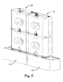
- FIG. 6 is a perspective view of several of the containers shown supported on a pair of fluid-containing stands.
- FIG. 7 is a perspective view of the container shown supported on a stand with an attached drip-tray.
- FIG. 8 is a perspective view of the container shown supported on a stand with a drip-tray attached to a different portion of the stand.
- FIG. 9 is a perspective view of several of the containers shown supported on a pair of stands with several attached drip-trays.
- FIG. 10 is a perspective view of two fluid-holding containers constructed in accordance with another embodiment of the present invention shown supported on a stand with an attached drip-tray.
- FIG. 11 is a front elevational view of the containers and stand of FIG. 10 .
- FIG. 12 is a partial vertical sectional view of the containers of FIG. 10 .
- FIG. 13 is a partial vertical sectional view of one of the containers of FIG. 10 with dimensions of certain parts of the container.
- references to “one embodiment”, “an embodiment”, or “embodiments” mean that the feature or features being referred to are included in at least one embodiment of the technology.
- references to “one embodiment”, “an embodiment”, or “embodiments” in this description do not necessarily refer to the same embodiment and are also not mutually exclusive unless so stated and/or except as will be readily apparent to those skilled in the art from the description.
- a feature, structure, act, etc. described in one embodiment may also be included in other embodiments, but is not necessarily included.
- the present technology can include a variety of combinations and/or integrations of the embodiments described herein.
- FIG. 1 a fluid-holding container 10 constructed in accordance with an embodiment of the invention is illustrated.
- the container 10 is designed for storing and dispensing vehicle lubricants, motor oils, gasoline, cleaning fluids, and other fluids or products commonly used in or on motor vehicles and is sized and designed for use in vehicle service centers or other applications with limited available floor space.
- An embodiment of the container 10 is rotationally molded from plastics or other synthetic resin materials, but it may also be formed with other molding techniques and/or from other materials.
- the container 10 includes spaced-apart front and back walls 12 , 14 ; spaced-apart left and right side walls 16 , 18 ; and spaced-apart top and bottom walls 20 , 22 that together define an enclosed fluid-containing inner chamber.
- the intersection of the walls 12 , 14 , 16 , 18 , 20 , and 22 may be curved to form radiused edges and corners on the container.
- An embodiment of the container 10 is in the shape of a rectangular cube with a width that is at least twice its depth and a height that is about twice its depth. This shape allows the container 10 to be placed along walls, on shelves, and in other tight spaces without occupying too much floor space.
- the container 10 is 48 inches wide, 20 inches deep, and 36 inches tall; however, the principles of the present invention are not limited to containers of any particular shape or size.
- the container 10 also includes through walls 24 molded between the front wall 12 and the back wall 14 that define a central through-hole 26 extending horizontally between the front wall 12 and the back wall 14 .
- the integrally molded through-hole 26 provides structural rigidity to the container by bridging the front and back walls 12 , 14 so that the container doesn't bulge excessively when filled with fluids and/or when stacked with other containers. This, along with the shape and size of the containers permits it to occupy less floor space.
- the through-hole 26 is oval in shape and has flared front and rear opening and a width 1-4 times its height.
- An embodiment of the through-hole 26 is 1 ⁇ 8-1 ⁇ 4 as wide as the container and approximately 1 ⁇ 4 the height of the container.
- a particular embodiment of the through-hole 26 is approximately 10′′ wide and 3′′ tall as measured from the center of the container and approximately 14′′ wide and 5′′ tall as measured from the outer periphery of its flared openings.
- an embodiment of the container 10 also has two top fill openings 28 , 30 in its top wall 20 .
- the top fill openings 28 , 30 are preferably 2′′ in diameter and are flush-mounted in the top wall and include molded-in, internally threaded metal sockets for receiving externally threaded caps or plugs 32 , 34 .
- the container also includes a front fill opening 36 that is angled relative to the top wall and front wall.
- the front fill opening 36 is also preferably 2′′ in diameter and includes a molded-in, internally threaded metal socket for receiving an externally threaded cap 38 .
- a recess 40 is formed in the intersection of the bottom wall 22 and the front wall 12 of the container to provide access to the front fill opening 36 of another container placed beneath it to facilitate filling of the containers when they are stacked as shown in FIG. 6 .
- the container 10 also includes three bottom drains 42 , 44 , 46 to permit dispensing of fluids from any side of the container.
- the drains 42 , 44 , 46 are preferably 1′′ in diameter and also include molded-in, internally threaded metal sockets for receiving externally threaded drain plugs, hoses 48 , and/or valves 50 as shown in FIG. 10 .
- Volume markings 52 in gallons or some other unit may be molded in the front wall 12 and right side wall 18 of the container. Other markings may also be molded in or printed on the container.
- one or more of the containers 10 may be placed on one or more containment type stands 54 to catch any fluids that drip or otherwise leak from the containers.
- One or more of the containers 10 may also be supported on elevated type stands 56 as shown in FIGS. 7, 8, and 9 .
- One or more drip trays 58 may be attached to the legs of the stands.
- the drip trays 58 and hoses 48 and valves 50 may be placed on the short or long side of the container to facilitate dispensing liquids from multiple sides of the container.
- FIGS. 10-13 depict a container 100 constructed in accordance with another embodiment of the invention.
- the container is similar to the container 10 described above except that it is larger and includes two circular-shaped through-holes or kiss-throughs 102 , 104 .
- the container also includes spaced-apart front and back walls 106 , 108 ; spaced-apart left and right side walls 110 , 112 ; and spaced-apart top and bottom walls 114 , 116 that together define an enclosed fluid-containing inner chamber.
- Through walls 118 , 120 are molded between the front wall 106 and the back wall 108 to define the through-holes 102 , 104 .
- these through-holes 102 , 104 provide structural rigidity to the container by bridging the front and back walls of the container so that multiple containers may be stacked.
- the through-holes 102 , 104 also include structure for mounting or otherwise supporting the container 100 against a wall, column, or other support.
- FIG. 12 shows one of the through-holes 102 in more detail.
- the through-hole 102 has an inwardly extending ledge 106 or other projection that creates a reduced diameter passageway that divides the kiss-through into a front portion 108 and a rear portion 110 .
- the front portion 108 flares outwardly from the ledge 106 toward the front wall of the container, and the rear portion 110 flares outwardly from the ledge 106 toward the rear wall of the container.
- FIG. 13 depicts specific dimensions (all in inches) of an embodiment of the kiss-through 102 at several points.
- the through-hole 104 is not shown in detail in FIGS. 12 and 13 but is identical to the through-hole 102 .
- the through-holes 102 , 104 are configured to receive mounting hardware to secure the container 100 against the wall or support S.
- An embodiment of the mounting hardware includes a relatively larger first washer 122 ; a relatively smaller second washer 124 ; and a bolt, screw, nail, or other fastener 126 .
- the first washer 122 is first inserted into the front portion 108 of the kiss-through 102 and placed against the front of the ledge 106 , the second washer 124 is then placed over the first washer, and the fastener 126 is then inserted through the holes in the first and second washers and screwed or otherwise driven into the wall or other support S. These steps may then be repeated with a fastener and washers in the second kiss-through 104 .
- the through-holes and mounting hardware cooperatively permit the container to compress and expand vertically without pulling the fasteners from the wall or other support.
- the outside diameter of the first washer 122 is greater than the diameter of the passageway defined by the ledge 106
- the outside diameter of the second smaller washer 124 is greater than the hole in the first larger washer 122 . This permits both washers 122 , 124 to be firmly pressed against the ledge 106 by the fastener 126 to securely hold the container against the wall or other support.
- the inside diameter of the hole in the larger washer 122 is greater than the outside diameter of the shaft of the fastener 126 so that the larger washer 122 and the fastener 126 may move vertically relative to one another.
- This can also be accomplished without the second washer 124 if the head of the fastener 126 is larger than the hole in the first washer 122 ; but two washers are preferred because they more easily slide up and down relative to one another.
- one or more of the containers 100 may be placed on one or more stands 128 to catch any fluids that drip or otherwise leak from the containers.
- One or more drip trays 130 may be attached to the legs of the stands.
Landscapes
- Engineering & Computer Science (AREA)
- Mechanical Engineering (AREA)
- General Engineering & Computer Science (AREA)
- Ceramic Engineering (AREA)
- Stackable Containers (AREA)
Abstract
Description
Claims (14)
Priority Applications (1)
| Application Number | Priority Date | Filing Date | Title |
|---|---|---|---|
| US15/150,100 US10370146B2 (en) | 2015-10-07 | 2016-05-09 | Fluid-holding container for vehicle service centers |
Applications Claiming Priority (3)
| Application Number | Priority Date | Filing Date | Title |
|---|---|---|---|
| US201562238194P | 2015-10-07 | 2015-10-07 | |
| US201662292932P | 2016-02-09 | 2016-02-09 | |
| US15/150,100 US10370146B2 (en) | 2015-10-07 | 2016-05-09 | Fluid-holding container for vehicle service centers |
Publications (2)
| Publication Number | Publication Date |
|---|---|
| US20170225829A1 US20170225829A1 (en) | 2017-08-10 |
| US10370146B2 true US10370146B2 (en) | 2019-08-06 |
Family
ID=59496164
Family Applications (1)
| Application Number | Title | Priority Date | Filing Date |
|---|---|---|---|
| US15/150,100 Active 2037-08-21 US10370146B2 (en) | 2015-10-07 | 2016-05-09 | Fluid-holding container for vehicle service centers |
Country Status (1)
| Country | Link |
|---|---|
| US (1) | US10370146B2 (en) |
Families Citing this family (1)
| Publication number | Priority date | Publication date | Assignee | Title |
|---|---|---|---|---|
| USD908594S1 (en) * | 2019-06-19 | 2021-01-26 | Front Runner Racks 2000 (Pty) Ltd. | Container for use on a roof rack |
Citations (4)
| Publication number | Priority date | Publication date | Assignee | Title |
|---|---|---|---|---|
| US3443710A (en) * | 1967-09-13 | 1969-05-13 | Monsanto Co | Container |
| US4881650A (en) * | 1988-06-14 | 1989-11-21 | Bartz Richard O | Fluid collection container |
| USD341314S (en) * | 1991-11-04 | 1993-11-16 | 159747 Canada, Inc. | Bottle |
| US20080245793A1 (en) * | 2007-04-05 | 2008-10-09 | The Coleman Company, Inc. | Insulated container with foot-operated lid |
-
2016
- 2016-05-09 US US15/150,100 patent/US10370146B2/en active Active
Patent Citations (4)
| Publication number | Priority date | Publication date | Assignee | Title |
|---|---|---|---|---|
| US3443710A (en) * | 1967-09-13 | 1969-05-13 | Monsanto Co | Container |
| US4881650A (en) * | 1988-06-14 | 1989-11-21 | Bartz Richard O | Fluid collection container |
| USD341314S (en) * | 1991-11-04 | 1993-11-16 | 159747 Canada, Inc. | Bottle |
| US20080245793A1 (en) * | 2007-04-05 | 2008-10-09 | The Coleman Company, Inc. | Insulated container with foot-operated lid |
Also Published As
| Publication number | Publication date |
|---|---|
| US20170225829A1 (en) | 2017-08-10 |
Similar Documents
| Publication | Publication Date | Title |
|---|---|---|
| US11497331B2 (en) | Gaskets and beverage container systems and kits comprising gaskets | |
| US10583961B2 (en) | Storage container systems | |
| US20140263136A1 (en) | Shelving System and Shelf for Same | |
| US20170202342A1 (en) | Cosmetic container comprising multiple compartments for separately containing various cream type cosmetics | |
| US10182670B2 (en) | Modular vape gear shelf and storage | |
| BR102014001243A2 (en) | COLLAPSABLE FITTING CONTAINER | |
| US8708203B2 (en) | Screw-on throat plug assembly | |
| US10370146B2 (en) | Fluid-holding container for vehicle service centers | |
| US20130341296A1 (en) | Shelf Connector and Shelving System Using Same | |
| US4984761A (en) | Electric fan cross-shaped base | |
| US4120250A (en) | Connecting structure for shelves | |
| KR101374534B1 (en) | Tool holder improves multi-tool storage compatibility | |
| KR20170053845A (en) | Tumbler | |
| US9776773B1 (en) | Fastener container | |
| US9615661B1 (en) | Multi level rack apparatus having intersecting arms | |
| US10308411B2 (en) | Shell and retainer containment system for dual bottles | |
| US20140103067A1 (en) | Stand-up caulk dispenser | |
| US10099910B2 (en) | Screw-lid removal and attachment device | |
| US5655460A (en) | Interconnectible spacers for supporting an article from a base surface | |
| CN208291646U (en) | A kind of material evidence inspection bucket | |
| EP4013693A1 (en) | Gripping and closing device for a keg type container | |
| US20210053723A9 (en) | Bottle | |
| KR200484858Y1 (en) | Multi-connectable container | |
| US20050151453A1 (en) | Storage unit for stacking multiple containers with lids | |
| AU641978B2 (en) | Kitchen storage unit |
Legal Events
| Date | Code | Title | Description |
|---|---|---|---|
| AS | Assignment |
Owner name: SNYDER INDUSTRIES, INC., NEBRASKA Free format text: ASSIGNMENT OF ASSIGNORS INTEREST;ASSIGNORS:EITZMANN, NICK;OLTMAN, DARRELL;REEL/FRAME:038520/0919 Effective date: 20160503 |
|
| STPP | Information on status: patent application and granting procedure in general |
Free format text: NOTICE OF ALLOWANCE MAILED -- APPLICATION RECEIVED IN OFFICE OF PUBLICATIONS |
|
| AS | Assignment |
Owner name: ANTARES CAPITAL LP, AS COLLATERAL AGENT, ILLINOIS Free format text: GRANT OF SECURITY INTEREST IN PATENT RIGHTS;ASSIGNORS:NORWESCO, LLC;SNYDER INDUSTRIES, LLC;REEL/FRAME:048711/0088 Effective date: 20190326 Owner name: ANTARES CAPITAL LP, AS COLLATERAL AGENT, ILLINOIS Free format text: GRANT OF SECURITY INTEREST IN PATENT RIGHTS;ASSIGNORS:NORWESCO, LLC;SNYDER INDUSTRIES, LLC;REEL/FRAME:048711/0141 Effective date: 20190326 |
|
| AS | Assignment |
Owner name: SNYDER INDUSTRIES, LLC, NEBRASKA Free format text: ENTITY CONVERSION;ASSIGNOR:SNYDER INDUSTRIES, INC.;REEL/FRAME:050405/0456 Effective date: 20190326 |
|
| STPP | Information on status: patent application and granting procedure in general |
Free format text: PUBLICATIONS -- ISSUE FEE PAYMENT VERIFIED |
|
| STCF | Information on status: patent grant |
Free format text: PATENTED CASE |
|
| AS | Assignment |
Owner name: ANTARES CAPITAL LP, AS THE COLLATERAL AGENT, ILLINOIS Free format text: SECURITY INTEREST;ASSIGNOR:TANK HOLDING CORP.;REEL/FRAME:059567/0662 Effective date: 20220331 Owner name: TANK HOLDING CORP., NEBRASKA Free format text: CHANGE OF NAME;ASSIGNOR:SNYDER INDUSTRIES, LLC;REEL/FRAME:059458/0806 Effective date: 20201223 |
|
| AS | Assignment |
Owner name: TANK HOLDING CORP., NEBRASKA Free format text: RELEASE BY SECURED PARTY;ASSIGNOR:ANTARES CAPITAL LP, AS COLLATERAL AGENT;REEL/FRAME:059474/0086 Effective date: 20220331 Owner name: SNYDER INDUSTRIES, LLC, NEBRASKA Free format text: RELEASE BY SECURED PARTY;ASSIGNOR:ANTARES CAPITAL LP, AS COLLATERAL AGENT;REEL/FRAME:059474/0086 Effective date: 20220331 |
|
| MAFP | Maintenance fee payment |
Free format text: PAYMENT OF MAINTENANCE FEE, 4TH YEAR, LARGE ENTITY (ORIGINAL EVENT CODE: M1551); ENTITY STATUS OF PATENT OWNER: LARGE ENTITY Year of fee payment: 4 |