US10367653B2 - Transmitting data in PET system - Google Patents
Transmitting data in PET system Download PDFInfo
- Publication number
- US10367653B2 US10367653B2 US15/660,792 US201715660792A US10367653B2 US 10367653 B2 US10367653 B2 US 10367653B2 US 201715660792 A US201715660792 A US 201715660792A US 10367653 B2 US10367653 B2 US 10367653B2
- Authority
- US
- United States
- Prior art keywords
- collecting module
- data packet
- collecting
- instruction information
- module
- Prior art date
- Legal status (The legal status is an assumption and is not a legal conclusion. Google has not performed a legal analysis and makes no representation as to the accuracy of the status listed.)
- Active
Links
Images


Classifications
-
- H—ELECTRICITY
- H04—ELECTRIC COMMUNICATION TECHNIQUE
- H04L—TRANSMISSION OF DIGITAL INFORMATION, e.g. TELEGRAPHIC COMMUNICATION
- H04L69/00—Network arrangements, protocols or services independent of the application payload and not provided for in the other groups of this subclass
- H04L69/08—Protocols for interworking; Protocol conversion
-
- H—ELECTRICITY
- H04—ELECTRIC COMMUNICATION TECHNIQUE
- H04L—TRANSMISSION OF DIGITAL INFORMATION, e.g. TELEGRAPHIC COMMUNICATION
- H04L12/00—Data switching networks
- H04L12/28—Data switching networks characterised by path configuration, e.g. LAN [Local Area Networks] or WAN [Wide Area Networks]
- H04L12/40—Bus networks
- H04L12/403—Bus networks with centralised control, e.g. polling
-
- G—PHYSICS
- G01—MEASURING; TESTING
- G01T—MEASUREMENT OF NUCLEAR OR X-RADIATION
- G01T1/00—Measuring X-radiation, gamma radiation, corpuscular radiation, or cosmic radiation
- G01T1/29—Measurement performed on radiation beams, e.g. position or section of the beam; Measurement of spatial distribution of radiation
- G01T1/2914—Measurement of spatial distribution of radiation
- G01T1/2985—In depth localisation, e.g. using positron emitters; Tomographic imaging (longitudinal and transverse section imaging; apparatus for radiation diagnosis sequentially in different planes, steroscopic radiation diagnosis)
-
- H—ELECTRICITY
- H04—ELECTRIC COMMUNICATION TECHNIQUE
- H04L—TRANSMISSION OF DIGITAL INFORMATION, e.g. TELEGRAPHIC COMMUNICATION
- H04L12/00—Data switching networks
- H04L12/28—Data switching networks characterised by path configuration, e.g. LAN [Local Area Networks] or WAN [Wide Area Networks]
- H04L12/40—Bus networks
- H04L12/40006—Architecture of a communication node
- H04L12/40032—Details regarding a bus interface enhancer
-
- H—ELECTRICITY
- H04—ELECTRIC COMMUNICATION TECHNIQUE
- H04L—TRANSMISSION OF DIGITAL INFORMATION, e.g. TELEGRAPHIC COMMUNICATION
- H04L69/00—Network arrangements, protocols or services independent of the application payload and not provided for in the other groups of this subclass
- H04L69/06—Notations for structuring of protocol data, e.g. abstract syntax notation one [ASN.1]
Definitions
- the present disclosure relates to transmitting data in a Positron Emission Tomography (PET) system.
- PET Positron Emission Tomography
- a PET system is a molecular imaging device.
- a tracer containing positron-emitting nuclides may emit positrons e+ during a decay process.
- the emitted positron e+ after moving a distance in a subject, may meet a negatron e ⁇ in surroundings and then an annihilation event may occur, thereby generating a pair of ⁇ -photons having equal energy (511 KeV) and propagating in opposite directions (about 180 degrees).
- the pair of ⁇ -photons may be detected by a detector of the PET system, thus allowing for analysis on the positrons to obtain a concentration distribution of the tracer in the subject.
- the detector of the PET system may include a plurality of axially arranged detector rings. Each detector ring may be assembled from a plurality of collecting modules. A positron annihilation event may occur in an internal space formed by the plurality of the detector rings. The pair of ⁇ -photons generated in the positron annihilation event may be incident on a pair of collecting modules in opposite directions and detected by the pair of collecting modules.
- a collecting module may include a scintillation crystal and a photoelectric conversion circuit. The collecting module may digitalize the collected ⁇ -photon signal to obtain data (such as, energy information, time information and so on) for determining a coincidence event.
- NMS NEUSOFT MEDICAL SYSTEMS CO., LTD.
- NMS NEUSOFT MEDICAL SYSTEMS CO., LTD.
- CT Magnetic Resonance Imaging
- PET Positron Emission Tomography
- LINAC Linear Accelerator
- biochemistry analyser Currently, NMS' products are exported to over 60 countries and regions around the globe, serving more than 5,000 renowned customers.
- NMS has been committed to the study of avoiding secondary potential harm caused by excessive X-ray irradiation to the subject during the CT scanning process.
- the present disclosure provides a PET system, a method and device for transmitting data in the PET system, which can simplify a structure of the device for transmitting data in the PET system.
- a PET system that include a detector and a host computer, where the detector includes a plurality of detector rings, each of the detector rings including n number of collecting modules arranged in a circumferential direction of the detector ring, a first collecting module of the n number of collecting modules coupled with the host computer, an n-th collecting module of the n number of collecting module coupled with a (n ⁇ 1)-th collecting module, an i-th collecting module coupled with a (i ⁇ 1)-th collecting module.
- n is an integer greater than 1
- i is an integer greater than 1 and less than n.
- the n-th collecting module is configured to transmit a data packet collected by itself to the (n ⁇ 1)-th collecting module; the i-th collecting module is configured to transmit a data packet obtained by superposing a data packet collected by itself with a data packet received from a (i+1)-th collecting module to the (i ⁇ 1)-th collecting module; the first collecting module is configured to transmit a data packet obtained by superposing a data packet collected by itself with a data packet received from a second collecting module to the host computer; and the host computer is configured to conduct a determination of a coincidence event based on the data packet received from the first collecting module.
- the first collecting module is further configured to receive instruction information from the host computer, obtain a control instruction corresponding to the first collecting module from the instruction information, and transmit the instruction information to the second collecting module.
- the i-th collecting module is further configured to receive the instruction information from the (i ⁇ 1)-th collecting module, obtain a control instruction corresponding to the i-th collecting module from the instruction information, and transmit the instruction information to the (i+1)-th collecting module.
- the n-th collecting module is further configured to receive the instruction information from the (n ⁇ 1)-th collecting module, and obtain a control instruction corresponding to the n-th collecting module from the instruction information.
- the n number of collecting modules are coupled in sequence by a serial bus including an uplink and a downlink; the uplink is configured to transmit a data packet from the j-th collecting module to the (j ⁇ 1)-th collecting modules, where j is an integer greater than 1 but not greater than n; and the downlink is configured to transmit the instruction information from the (j ⁇ 1)-th collecting module to the j-th collecting module.
- a data packet collected by each of the collecting modules includes a time slot, an address of the collecting module and data information.
- the data packet transmitted from the i-th collecting module to the (i ⁇ 1)-th collecting module is obtained by superposing the data packet collected by the i-th collecting module with the data packet received from the (i+1)-th collecting module in an order of respective addresses of the collecting modules.
- the data packet transmitted from the first collecting module to the host computer is obtained by superposing the data packet collected by the first collecting module with the data packet received from the second collecting module in the order of respective addresses of the collecting modules.
- the device includes n number of collecting modules in a serial connection, where the n number of collecting modules include an n-th collecting module, an i-th collecting module and a first collecting module, n is an integer greater than 1, i is an integer greater than 1 and less than n; the n-th collecting module is configured to transmit a data packet collected by itself to a (n ⁇ 1)-th collecting module; the i-th collecting module is configured to transmit a data packet obtained by superposing a data packet collected by itself with a data packet received from a (i+1)-th collecting module to the (i ⁇ 1)-th collecting module; the first collecting module is configured to transmit a data packet obtained by superposing a data packet collected by itself with a data packet received from a second collecting module to a host computer; and the host computer is configured to conduct a determination of a coincidence event based on the data packet received from the first collecting module.
- the first collecting module is further configured to receive instruction information from the host computer, obtain a control instruction corresponding to the first collecting module from the instruction information, and transmit the instruction information to the second collecting module.
- the i-th collecting module is further configured to receive the instruction information from the (i ⁇ 1)-th collecting module, obtain a control instruction corresponding to the i-th collecting module from the instruction information, and transmit the instruction information to the (i+1)-th collecting module.
- the n-th collecting module is further configured to receive the instruction information from the (n ⁇ 1)-th collecting module, and obtain a control instruction corresponding to the n-th collecting module from the instruction information.
- the n number of collecting modules are coupled in sequence by a serial bus including an uplink and a downlink.
- the uplink is configured to transmit a data packet from the j-th collecting module to the (j ⁇ 1)-th collecting modules, where j is an integer greater than 1 but not greater than n.
- the downlink is configured to transmit the instruction information from the (j ⁇ 1)-th collecting module to the j-th collecting module.
- a data packet collected by each of the collecting modules includes a time slot, an address of the collecting module and data information.
- the data packet transmitted from the i-th collecting module to the (i ⁇ 1)-th collecting module is obtained by superposing the data packet collected by the i-th collecting module with the data packet received from the (i+1)-th collecting module in an order of respective addresses of the collecting modules.
- the data packet transmitted from the first collecting module to the host computer is obtained by superposing the data packet collected by the first collecting module with the data packet received from the second collecting module in the order of respective addresses of the collecting modules.
- n number of collecting modules including an n-th collecting module, an i-th collecting module, and a first collecting module; the n number of collecting modules are in a serial connection; n is an integer greater than 1; and i is an integer greater than 1 and less than n.
- the method includes: the n-th collecting module transmitting a data packet collected by itself to a (n ⁇ 1)-th collecting module; the i-th collecting module transmitting a data packet obtained by superposing a data packet collected by itself with a data packet received from a (i+1)-th collecting module to the (i ⁇ 1)-th collecting module; the first collecting module transmitting a data packet obtained by superposing a data packet collected by itself with a data packet received from a second collecting module to a host computer; and the host computer conducting a determination of a coincidence event based on the data packet received from the first collecting module.
- the method further includes: the first collecting module receiving instruction information from the host computer, obtaining a control instruction corresponding to the first collecting module from the instruction information, and transmitting the instruction information to the second collecting module; the i-th collecting module receiving the instruction information from the (i ⁇ 1)-th collecting module, obtaining a control instruction corresponding to the i-th collecting module from the instruction information, and transmitting the instruction information to the (i+1)-th collecting module; and the n-th collecting module receiving the instruction information from the (n ⁇ 1)-th collecting module, and obtaining a control instruction corresponding to the n-th collecting module from the instruction information.
- the n number of collecting modules are coupled in sequence by a serial bus including an uplink and a downlink.
- the uplink is configured to transmit a data packet from the j-th collecting module to the (j ⁇ 1)-th collecting modules, where j is an integer greater than 1 but not greater than n.
- the downlink is configured to transmit the instruction information from the (j ⁇ 1)-th collecting module to the j-th collecting module.
- a data packet collected by each of the collecting modules itself includes a time slot, an address of the collecting module and data information.
- the data packet transmitted from the i-th collecting module to the (i ⁇ 1)-th collecting module is obtained by superposing the data packet collected by the i-th collecting module with the data packet received from the (i+1)-th collecting module in an order of respective addresses of the collecting modules.
- the data packet transmitted from the first collecting module to the host computer is obtained by superposing the data packet collected by the first collecting module with the data packet received from the second collecting module in the order of respective addresses of the collecting modules.
- FIG. 1 is a schematic diagram of a data transmitting device in a PET system according to an example of the present disclosure.
- FIG. 2 illustrates a connection between any two adjacent collecting modules according to an example of the present disclosure.
- FIG. 3 is a schematic diagram of a data transmitting device in a PET system according to another example of the present disclosure.
- FIG. 4 is a flowchart of a method of transmitting data in a PET system according to an example of the present disclosure.
- FIG. 5 is a flowchart of a method of transmitting data in a PET system according to another example of the present disclosure.
- a data transmitting device in a PET system may include a plurality of collecting modules, a data gathering module and a coincidence processing module.
- Each of the collecting modules may be coupled with the data gathering module.
- Each of the collecting modules may send the respective collected data packet to the data gathering module.
- the data gathering module may gather the received data packets and then send the gathered data packet to the coincidence processing module, where the coincidence processing module may be configured to obtain coincidence data by determining a coincidence event.
- the coincidence processing module may transmit the coincidence data to a host computer for reconstructing an image. In this way, data transmission in the PET system may be realized.
- a bus configured to transmit instructions is coupled with each of the collecting modules, so as to complete relevant configuration for the collecting module and read a status of the collecting module.
- more collecting modules may be configured in the data transmitting device.
- connection of the various lines may be relatively complex; in addition, the data gathering module may need a large number of interfaces for coupling each of the collecting modules, which may be adverse to the device integration. Therefore, this data transmitting mode may not meet such a new requirement.
- a requirement for transmitting data in real-time may be higher. If it is required that time for configuring the collecting module and data transmitting is shortened, low-speed buses used in this the data transmitting mode may not satisfy such a requirement.
- the collecting modules distributed in the PET system may be coupled in a serial non-closed-loop connection manner with a high-speed serial bus.
- the serial bus may include an uplink and a downlink.
- the uplink may be configured to transmit a data packet from the j-th collecting module to the (j ⁇ 1)-th collecting modules
- the downlink may be configured to transmit instruction information from the (j ⁇ 1)-th collecting module to the j-th collecting module so as to realize functions such as configuration for the collecting module.
- j is an integer greater than 1 but not greater than a number of collecting modules in a detector ring of the PET system.
- the data transmitting device does not include the data gathering module and the coincidence processing module, thereby simplifying the structure of the data transmitting device.
- the data gathering may be achieved in a way that each of the collecting modules superposes the collected data packet step-by-step during the data transmitting process. In this way, the integrity of the collected data packet may be ensured and a data packet may be transmitted in real-time.
- a host computer may be configured to conduct a determination of a coincidence event based on a special data structure formed by superposing the collected data packets during the data transmitting process, so as to obtain coincidence data and reconstruct a relevant image according to the coincidence data.
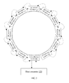
- FIG. 1 is a schematic diagram of a data transmitting device in a PET system according to an example of the present disclosure.
- the data transmitting device may include n number of collecting modules, such as an n-th collecting module 101 , an i-th collecting module 102 (such as a second collecting module 104 ) and a first collecting module 103 .
- the n number of collecting modules may be coupled in a serial connection.
- n is an integer greater than 1
- i is an integer greater than 1 and less than n, respectively.
- the data transmitting device includes n number of collecting modules.
- the first collecting module 103 is coupled with a host computer 200 ; the n-th collecting module 101 is the last collecting module in the serial connection; and the i-th collecting module 102 is located between the first collecting module 103 and the n-th collecting module 101 .
- n 5
- i may be 2, 3, and 4.
- the data transmitting device includes five collecting modules in total, such as, a first collecting module, a second collecting module, a third collecting module, a fourth collecting module, and a fifth collecting module. These five modules may be coupled in a serial connection.
- n number of collecting modules may be in a serial connection, e.g., the collecting modules are coupled in a serial non-closed-loop connection manner with a serial bus.
- the data transmitting speed is high on the serial bus, thereby ensuring data transmission in real-time.
- the serial bus may include an uplink and a downlink. As shown in FIG. 1 , the uplink is represented by a dotted line, and the downlink is represented by a full line.
- FIG. 2 illustrates a connection between any two adjacent collecting modules 210 and 220 .
- the uplink (TXD, RXD) may be configured to transmit a data packet
- the downlink (TXC, RXC) may be configured to transmit instruction information.
- a set of serial buses may be enough to couple all collecting modules together. The structure of the device is simple and facilitates the device integration.
- the n-th collecting module 101 may be configured to transmit a data packet collected by itself to the (n ⁇ 1)-th collecting module.
- the i-th collecting module 102 may be configured to transmit a data packet obtained by superposing a data packet collected by itself with a data packet received from the (i+1)-th collecting module to the (i ⁇ 1)-th collecting module.
- the first collecting module 103 may be configured to transmit a data packet obtained by superposing a data packet collected by itself with a data packet received from the second collecting module 104 to the host computer 200 , so that the host computer 200 may conduct a determination of a coincidence event based on the data packet received from the first collecting module.
- the collecting module when it works, it may collect a data packet and transmit the collected data packet. Driven by device clock ticks, the collected data packet may be orderly transmitted from the n-th collecting module in a forward direction. Each of the collecting modules except for the n-th collecting module may superpose the data packet collected by itself with the received data packet to form a superposed data packet and may continue to transmit the superposed data packet in the forward direction; and finally the first collecting module may transmit the superposed data packet to the host computer. This process is lossless superposition of the data packet.
- photon detection data collected by each of the collecting modules may include time information, energy information and so on when photons are detected.
- the photon detection data may be used for the subsequent determination of a coincidence event.
- the collecting module may package the photon detection data collected in a particular time slot into a data packet, add the time slot and address information of the collecting module into the data packet and then transmit the data packet to a collecting module previous to the collecting module.
- the time slot may be a time interval of a preset length, for example, 10:05 am to 10:10 am.
- the data packet transmitted from the i-th collecting module to the (i ⁇ 1)-th collecting module may be obtained by superposing the data packet collected by the i-th collecting module with the data packet received from the (i+1)-th collecting module in an order of respective addresses of the collecting modules.
- the data packet transmitted from the first collecting module to the host computer may be obtained by superposing the data packet collected by the first collecting module with the data packet received from the second collecting module in the order of respective addresses of the collecting modules.
- the data packet superposed by a collecting module may be obtained by superposing the data packet collected by itself with the received data packet in the order of respective addresses of the collecting modules.
- each of the collecting modules in the data transmitting device may work independently to recognize photon signals.
- the collecting module may collect a data packet.
- the data packet may include detailed information such as a time slot, an address of the collecting module, data (e.g., time information and energy information) and so on.
- Each of the collecting modules except for the first collecting module may superpose the collected data packet with a received data packet to generate a new data packet and transmit the new data packet to a previous collecting module.
- the first collecting module may superpose the collected data packet by itself with a received data packet to generate a new data packet and transmit the new data packet to the host computer.
- the contents of the data packet received by the host computer can be as shown in Table 1.
- Time slot Address 1 Data Time slot Address 2 Data . . . . . . . Time slot Address i Data . . . . . . . Time slot Address n-1 Data Time slot Address n Data
- the host computer may store the data packet received from the first collecting module into a memory unit corresponding to the host computer and then the processor of the host computer may conduct a determination of a coincidence event with the received data packet. For determining a coincidence event, the processor may firstly combine a plurality of data packets from the same time slot into a data combination, and then determine a coincidence event with the data combination based on a correspondence between respective addresses of the collecting modules and the data packets. In this way, a series of coincidence events may be determined and an image may be reconstructed based on the coincidence events.
- each of the data packet collected by the n-th collecting module, the data packet superposed by the i-th collecting module, and the data packet superposed by the first collecting module may be transmitted by a corresponding uplink.
- the n-th collecting module may transmit the data packet collected by itself to the (n ⁇ 1)-th collecting module over the corresponding uplink; the i-th collecting module may transmit a superposed data packet to the (i ⁇ 1)-th collecting module over the corresponding uplink; and the first collecting module may transmit a superposed data packet to the host computer over the corresponding uplink.
- the first collecting module may further configured to receive instruction information from the host computer, obtain a control instruction corresponding to the first collecting module from the instruction information and transmit the instruction information to the second collecting module.
- the i-th collecting module may further configured to receive the instruction information from the (i ⁇ 1)-th collecting module, obtain a control instruction corresponding to the i-th collecting module from the instruction information and transmit the instruction information to the (i+1)-th collecting module.
- the n-th collecting module may further configured to receive the instruction information from the (n ⁇ 1)-th collecting module and obtain a control instruction corresponding to the n-th collecting module from the instruction information.
- the collecting module may transmit a superposed data packet while receiving the instruction information.
- the instruction information may include respective addresses of the collecting modules and a control instruction corresponding to each of the collecting modules.
- the instruction information may be shown in Table 2.
- Control instruction 1 Address 2 Control instruction 2 . . . . . Address i Control instruction i . . . . . Address n-1 Control instruction n-1 Address n Control instruction n
- Each of the collecting modules may obtain a corresponding control instruction according to a respective address.
- each of the collecting modules may obtain a corresponding control instruction based on the instruction information, respectively, and complete related operations according to the corresponding control instruction, such as, the configuration of a parameter table, feedback of status information, and so on.
- a data packet transmitted by a collecting module may include not only data for determination of a coincidence event, but also parameter information to be fed back according to the received control instruction, such as, temperature, voltage, current and so on.
- instruction information may be transmitted over a downlink.
- the first collecting module may receive instruction information from the host computer over the corresponding downlink and transmit the instruction information to the second collecting module over the corresponding downlink;
- the i-th collecting module may receive the instruction information from the (i ⁇ 1)-th collecting module over the corresponding downlink and transmit the instruction information to the (i+1)-th collecting module over the corresponding downlink;
- the n-th collecting module may receive the instruction information from the (n ⁇ 1)-th collecting module over the corresponding downlink.
- the instruction information may further be transmitted by a high-speed serial bus, an objective of high-speed configuration may be achieved.
- a plurality of collecting modules in a data transmitting device are coupled in sequence by a serial bus.
- the data transmitting device is a non-closed-loop connection structure, which facilitates increasing a number of collecting modules.
- the number of collecting modules of the data transmitting device may be set based on a requirement for the PET system.
- the data packets in the device may be transmitted in a forward direction from the last collecting module (e.g., the n-th collecting module). During this process, the data packets are transmitted in a unidirectional way.
- a high-speed serial bus may be configured to transmit instruction information.
- the data transmitting device may not include the data gathering module and the coincidence determining module, and the structure of the device is relatively simple.
- the data transmitting device may transmit the data packet superposed by the first collecting module to the memory of the host computer.
- the processor of the host computer may conduct a determination of a coincidence event based on the particular data structure in the data packet. In this way, coincidence algorithm may be simplified and the flexibility of the device may be improved.
- FIG. 3 is a schematic diagram of a data transmitting device in a PET system according to another example of the present disclosure.
- the data transmitting device in the PET system provided in one or more examples of the present disclosure will be further described below by taking a data transmitting device including 12 collecting modules in a PET system as an example.
- the data transmitting device may include 12 collecting modules, where the first collecting module 301 to the twelfth collecting module 312 is coupled in sequence by a serial bus.
- the serial bus may include an uplink and a downlink.
- the uplink may be configured to transmit a data packet.
- the downlink may be configured to transmit instruction information from a user.
- the uplink is represented by a dotted line, and the downlink is represented by a full line.
- the first collecting module may also be coupled with a host computer 320 by a serial bus.
- the host computer 320 may transmit a synchronizing signal to each of the collecting modules 301 , 302 , 303 , 304 , 305 , 306 , 307 , 308 , 309 , 310 311 , 312 one by one over the corresponding downlink. Unified collection time may be determined for each of the collecting modules.
- the twelfth collecting module 312 may begin to transmit the collected data packet to the eleventh collecting module 311 , and then the eleventh collecting module 311 may transmit the data packet obtained by superposing the received data packet and the data packet collected by itself to the tenth collecting module 310 , and so on, until the first collecting module 301 may transmit the data packet obtained by superposing the received data packet from the second collecting module 302 and the data packet collected by itself to the host computer 320 , thus completing transmission of the data packets. Furthermore, the host computer 320 may further transmit instruction information to the first collecting module 301 . The instruction information may be transmitted one by one in a backward direction until to the twelfth collecting module 312 .
- Each of the collecting modules may obtain its own corresponding control instruction from the instruction information based on the address of the collecting module.
- the data for determining a coincidence event may be transmitted, but also the data (such as, temperature, voltage, current and so on) collected according to the instruction information may be transmitted.
- the collecting modules are coupled in the manner of serial non-closed-loop connection in one or more examples of the present disclosure.
- the last collecting module may transmit a data packet collected by itself in a forward direction; each of collecting modules other than the last collecting module may transmit a data packet which is obtained by superposing a data packet collected by itself to a received data packet in the forward direction; and finally, a data packet comprising respective data packets collected by the collecting modules may be transmitted from the first collecting module to the host computer for determining a coincidence event.
- the first collecting module may generate the data packet comprising respective data packets collected by the collecting modules by superposing a data packet collected by itself to a data packet received from the second collecting module. Gathering of respective data packets collected by the collecting modules is achieved during data transmission without an additional data gathering module and a large number of data interfaces.
- the connection structure of the data transmitting device may be simple, which facilitates the device integration and expansion of the number of collecting modules.
- a PET system may include a detector and a host computer.
- the detector may include a plurality of detector rings and each of the detector rings may include the data transmitting device as described above.
- FIG. 4 is a flowchart of a method of transmitting data in a PET system according to an example of the present disclosure.
- the method of transmitting data may be applied to a detector ring in the PET system.
- the detector ring may include n number of collecting modules coupled in sequence.
- the n number of collecting modules may include an n-th collecting module, an i-th collecting module and a first collecting module.
- the collecting modules are in a serial connection. Where n is an integer greater than 1 and i is an integer greater than 1 but less than n.
- n number of collecting modules may be in a serial connection such as coupled in sequence by a serial bus.
- the serial bus may include an uplink and a downlink.
- the method of transmitting data may include blocks 401 to 403 .
- the n-th collecting module transmits a data packet collected by itself to a (n ⁇ 1)-th collecting module.
- the i-th collecting module transmits a data packet obtained by superposing a data packet collected by itself with a data packet received from a (i+1)-th collecting module to the (i ⁇ 1)-th collecting module.
- the first collecting module transmits a data packet obtained by superposing a data packet collected by itself with a data packet received from a second collecting module to a host computer, so that the host computer conducts a determination of a coincidence event based on the data packet received from the first collecting module.
- a data packet collected by each of the collecting modules may include a time slot, an address of the collecting module, and data information.
- the data packet transmitted from the i-th collecting module to the (i ⁇ 1)-th collecting module may be obtained by superposing the data packet collected by the i-th collecting module with the data packet received from the (i+1)-th collecting module in an order of respective addresses of the collecting modules.
- the data packet transmitted from the first collecting module to the host computer may be obtained by superposing the data packet collected by the first collecting module with the data packet received from the second collecting module in the order of respective addresses of the collecting modules.
- FIG. 5 is a flowchart of a method of transmitting data in a PET system according to another example of the present disclosure. Based on FIG. 4 , the method of transmitting data in the PET system provided in an example of the present disclosure may further include blocks 501 to 503 .
- the first collecting module receives instruction information from the host computer, obtains a control instruction corresponding to the first collecting module from the instruction information, and transmits the instruction information to the second collecting module.
- each of the data packet collected by the n-th collecting module, the data packet superposed by the i-th collecting module, and the data packet superposed by the first collecting module may be transmitted over an uplink.
- the i-th collecting module receives the instruction information from the (i ⁇ 1)-th collecting module, obtains a control instruction corresponding to the i-th collecting module from the instruction information, and transmits the instruction information to the (i+1)-th collecting module.
- the n-th collecting module receives the instruction information from the (n ⁇ 1)-th collecting module and obtains a control instruction corresponding to the n-th collecting module from the instruction information.
- the instruction information may be transmitted over a downlink.
- the collecting modules may be coupled in the manner of serial non-closed loop connection in one or more examples of the present disclosure, and the last collecting module may transmit the data packet collected by itself in a forward direction; each of other collecting modules other than the last collecting module may transmit a data packet obtained by superposing the received data packet and the data packet collected by itself one by one in the forward direction; and finally, a data packet collected by each of the collecting modules may be transmitted to the host computer for determining a coincidence event.
- the first collecting module may transmit a data packet obtained by superposing a data packet collected by itself with a data packet received from the second collecting module. Gathering of respective data packets collected by the collecting modules is achieved during transmission of the data packets without an additional data gathering module and a large number of data interfaces.
- the connection structure of the data transmitting device may thus be simple, which facilitates the device integration and expansion of the number of collecting modules.
- relational terms such as first, second and the like in this text are merely used for differentiating one entity or operation from another entity or operation rather than definitely requiring or implying any actual relationship or order between these entities or operations.
- the terms “comprising” and “including”, or any other variants thereof are intended to be non-exclusive, such that a process, a method, an article or a device comprising a series of elements includes not only those elements, but also other elements not explicitly listed, or further includes inherent elements of the process, the method, the article or the device.
- elements defined by the sentence of “comprising a . . . ” shall not be exclusive of additional same elements also existing in the process, the method, the article or the device.
- blocks of the method may be carried out directly by hardware, software modules executed by a processor, or by combination thereof.
- the software modules may be placed in a random-access memory (RAM), a memory, a read-only memory (ROM), an electrically programmable ROM, an electrically erasable programmable ROM, a register, a hard drive, a removable magnetic disk, a CD-ROM, or any type of storage medium that is well known in the prior art.
Landscapes
- Engineering & Computer Science (AREA)
- Signal Processing (AREA)
- Computer Networks & Wireless Communication (AREA)
- General Physics & Mathematics (AREA)
- High Energy & Nuclear Physics (AREA)
- Molecular Biology (AREA)
- Spectroscopy & Molecular Physics (AREA)
- Physics & Mathematics (AREA)
- Life Sciences & Earth Sciences (AREA)
- Health & Medical Sciences (AREA)
- Computer Security & Cryptography (AREA)
- Nuclear Medicine (AREA)
- Arrangements For Transmission Of Measured Signals (AREA)
- Selective Calling Equipment (AREA)
Abstract
Description
| TABLE 1 | |||
| | Address | 1 | Data |
| Time slot | Address 2 | Data | |
| . . . | . . . | . . . | |
| Time slot | Address i | Data | |
| . . . | . . . | . . . | |
| Time slot | Address n-1 | Data | |
| Time slot | Address n | Data | |
| TABLE 2 | |||
| |
|
||
| Address 2 | Control instruction 2 | ||
| . . . | . . . | ||
| Address i | Control instruction i | ||
| . . . | . . . | ||
| Address n-1 | Control instruction n-1 | ||
| Address n | Control instruction n | ||
Claims (11)
Applications Claiming Priority (3)
| Application Number | Priority Date | Filing Date | Title |
|---|---|---|---|
| CN201610615343.8A CN106230816B (en) | 2016-07-28 | 2016-07-28 | A system and method for realizing data transmission in a PET system |
| CN201610615343.8 | 2016-07-28 | ||
| CN201610615343 | 2016-07-28 |
Publications (2)
| Publication Number | Publication Date |
|---|---|
| US20180034659A1 US20180034659A1 (en) | 2018-02-01 |
| US10367653B2 true US10367653B2 (en) | 2019-07-30 |
Family
ID=57535698
Family Applications (1)
| Application Number | Title | Priority Date | Filing Date |
|---|---|---|---|
| US15/660,792 Active US10367653B2 (en) | 2016-07-28 | 2017-07-26 | Transmitting data in PET system |
Country Status (3)
| Country | Link |
|---|---|
| US (1) | US10367653B2 (en) |
| EP (1) | EP3276381B1 (en) |
| CN (1) | CN106230816B (en) |
Families Citing this family (4)
| Publication number | Priority date | Publication date | Assignee | Title |
|---|---|---|---|---|
| CN109632842B (en) * | 2018-12-29 | 2023-09-12 | 明峰医疗系统股份有限公司 | CT detector with module serial structure and use method thereof |
| CN112380029B (en) * | 2020-11-02 | 2023-01-24 | 上海联影医疗科技股份有限公司 | Synchronization control method, device, system and storage medium |
| EP4098201A1 (en) | 2021-06-03 | 2022-12-07 | Koninklijke Philips N.V. | Processing event data in pet imaging |
| CN114546772A (en) * | 2022-02-23 | 2022-05-27 | 深圳市洲明科技股份有限公司 | Equipment monitoring method and device, computer equipment and storage medium |
Citations (15)
| Publication number | Priority date | Publication date | Assignee | Title |
|---|---|---|---|---|
| WO2007015198A2 (en) | 2005-08-04 | 2007-02-08 | Koninklijke Philips Electronics N.V. | Modular signal processing backbone for pet |
| US20100085885A1 (en) * | 2007-04-04 | 2010-04-08 | Mitsubishi Electric Corporation | Communication system, management apparatus, communication apparatus and computer program |
| CN103099639A (en) | 2013-03-01 | 2013-05-15 | 江苏中惠医疗科技股份有限公司 | Ring topological structure of positron emission tomography (PET) imaging system and achieving method thereof |
| CN103491198A (en) | 2013-09-16 | 2014-01-01 | 上海交通大学 | Ten billion Ethernet transmission system used for positron emission computer tomography |
| US20150094571A1 (en) * | 2013-09-27 | 2015-04-02 | General Electric Company | Systems and methods for controlling motion of detectors having moving detector heads |
| US20160054455A1 (en) * | 2014-08-25 | 2016-02-25 | Kabushiki Kaisha Toshiba | Detector, nuclear medical imaging apparatus, pet-ct apparatus, and pet-mri apparatus |
| US20160073975A1 (en) * | 2014-09-17 | 2016-03-17 | General Electric Company | Systems and methods for imaging plural axial locations |
| US20160135768A1 (en) * | 2014-11-17 | 2016-05-19 | General Electric Company | Systems and methods for displaying a physiologic waveform |
| US20160354047A1 (en) * | 2015-06-03 | 2016-12-08 | General Electric Company | System and method for displaying variable duration image scans |
| US20170018099A1 (en) * | 2015-06-30 | 2017-01-19 | General Electric Company | Systems and methods for peak tracking and gain adjustment |
| US20170090047A1 (en) * | 2015-09-30 | 2017-03-30 | General Electric Company | Systems and methods for reduced size detector electronics |
| US20170090040A1 (en) * | 2015-09-30 | 2017-03-30 | General Electric Company | Systems and methods for imaging with multi-head camera |
| US20170139061A1 (en) * | 2015-11-17 | 2017-05-18 | Shenyang Neusoft Medical Systems Co., Ltd. | Determining a pair of compliance events |
| US20170325775A1 (en) * | 2015-09-18 | 2017-11-16 | Shanghai United Imaging Healthcare Co., Ltd. | System and method for computer tomography |
| US20170350993A1 (en) * | 2016-01-13 | 2017-12-07 | General Electric Company | Systems and methods for reducing polarization in imaging detectors |
-
2016
- 2016-07-28 CN CN201610615343.8A patent/CN106230816B/en active Active
-
2017
- 2017-07-26 US US15/660,792 patent/US10367653B2/en active Active
- 2017-07-27 EP EP17183500.2A patent/EP3276381B1/en active Active
Patent Citations (18)
| Publication number | Priority date | Publication date | Assignee | Title |
|---|---|---|---|---|
| WO2007015198A2 (en) | 2005-08-04 | 2007-02-08 | Koninklijke Philips Electronics N.V. | Modular signal processing backbone for pet |
| EP1913422A2 (en) | 2005-08-04 | 2008-04-23 | Koninklijke Philips Electronics N.V. | Scalable singles processing backbone for pet |
| CN101238392A (en) | 2005-08-04 | 2008-08-06 | 皇家飞利浦电子股份有限公司 | Modular Signal Processing Backbone for PET |
| EP1913422B1 (en) | 2005-08-04 | 2015-05-13 | Koninklijke Philips N.V. | Modular signal processing backbone for pet |
| US20100085885A1 (en) * | 2007-04-04 | 2010-04-08 | Mitsubishi Electric Corporation | Communication system, management apparatus, communication apparatus and computer program |
| CN103099639A (en) | 2013-03-01 | 2013-05-15 | 江苏中惠医疗科技股份有限公司 | Ring topological structure of positron emission tomography (PET) imaging system and achieving method thereof |
| CN103491198A (en) | 2013-09-16 | 2014-01-01 | 上海交通大学 | Ten billion Ethernet transmission system used for positron emission computer tomography |
| US20150094571A1 (en) * | 2013-09-27 | 2015-04-02 | General Electric Company | Systems and methods for controlling motion of detectors having moving detector heads |
| US20160054455A1 (en) * | 2014-08-25 | 2016-02-25 | Kabushiki Kaisha Toshiba | Detector, nuclear medical imaging apparatus, pet-ct apparatus, and pet-mri apparatus |
| US20160073975A1 (en) * | 2014-09-17 | 2016-03-17 | General Electric Company | Systems and methods for imaging plural axial locations |
| US20160135768A1 (en) * | 2014-11-17 | 2016-05-19 | General Electric Company | Systems and methods for displaying a physiologic waveform |
| US20160354047A1 (en) * | 2015-06-03 | 2016-12-08 | General Electric Company | System and method for displaying variable duration image scans |
| US20170018099A1 (en) * | 2015-06-30 | 2017-01-19 | General Electric Company | Systems and methods for peak tracking and gain adjustment |
| US20170325775A1 (en) * | 2015-09-18 | 2017-11-16 | Shanghai United Imaging Healthcare Co., Ltd. | System and method for computer tomography |
| US20170090047A1 (en) * | 2015-09-30 | 2017-03-30 | General Electric Company | Systems and methods for reduced size detector electronics |
| US20170090040A1 (en) * | 2015-09-30 | 2017-03-30 | General Electric Company | Systems and methods for imaging with multi-head camera |
| US20170139061A1 (en) * | 2015-11-17 | 2017-05-18 | Shenyang Neusoft Medical Systems Co., Ltd. | Determining a pair of compliance events |
| US20170350993A1 (en) * | 2016-01-13 | 2017-12-07 | General Electric Company | Systems and methods for reducing polarization in imaging detectors |
Non-Patent Citations (3)
| Title |
|---|
| European Patent Office, Extended European Search Report Issued in Application No. 17183500.2, Nov. 9, 2017, Germany, 10 pages. |
| Rajagopalan, R et al., "Data-Aggregation Techniques in Sensor Networks: A Survey," IEEE Communications Surveys & Tutorials, vol. 8, No. 4, Oct. 1, 2006, 16 pages. |
| State Intellectual Property Office of the People's Republic of China, Office Action and Search Report Issued in Application No. 201610615343.8, Nov. 1, 2018, 12 pages. (Submitted with Partial Translation). |
Also Published As
| Publication number | Publication date |
|---|---|
| US20180034659A1 (en) | 2018-02-01 |
| CN106230816B (en) | 2019-05-21 |
| EP3276381B1 (en) | 2022-01-19 |
| EP3276381A1 (en) | 2018-01-31 |
| CN106230816A (en) | 2016-12-14 |
Similar Documents
| Publication | Publication Date | Title |
|---|---|---|
| US10367653B2 (en) | Transmitting data in PET system | |
| US6239438B1 (en) | Dual acquisition imaging method and apparatus | |
| US9279888B2 (en) | System for online/offline singles-pairing with keeping/rejecting multi-coincidences for positron emission tomography | |
| US20070181814A1 (en) | Method and apparatus for determining depth of interactions in a detector for three-dimensional complete body screening | |
| US7132664B1 (en) | Method and apparatus for improving PET detectors | |
| EP3316002B1 (en) | Determining response lines for image reconstruction | |
| US6462342B1 (en) | Method and system for pet image reconstruction | |
| US20090008562A1 (en) | Method and Apparatus for Providing Depth-of-Interaction Detection Using Positron Emission Tomography (PET) | |
| RU2011118359A (en) | SHELL FOR A HYGROSCOPIC SCINTILING CRYSTAL FOR NUCLEAR IMAGE CONSTRUCTION | |
| JPH06347555A (en) | Position imaging device | |
| CN106821402B (en) | Method and device for constructing PET image | |
| CN102648856A (en) | Positron emission tomography scanner and coincidence judging and selecting method therein | |
| CN112587159B (en) | Methods and systems for PET detectors | |
| CN109998582A (en) | Coincidence judging and selecting method, device, equipment and medium | |
| US20110089327A1 (en) | Multimodality Imaging | |
| JP2002504224A (en) | Real-time PET imaging processor for single photon gamma camera | |
| US7863573B2 (en) | Positron emission tomography imaging system, detector, data processing apparatus, computer readable program product having positron emission tomography imaging program for user terminal, and method for positron emission tomography diagnosis | |
| WO2004005965A2 (en) | Pet coincidence processor | |
| CN104598356B (en) | A kind of event ordering method and device | |
| US9947116B2 (en) | Methods and systems for detector gap corrections | |
| US20240000401A1 (en) | Systems, apparatuses, and methods for data acquisition in pet | |
| CN102028485A (en) | PET scanner system and image reconstruction method in the same | |
| CN111466936B (en) | Clock synchronization method, device and computer equipment | |
| KR101363615B1 (en) | Radiation diagnosis apparatus | |
| Lewellen et al. | System integration of the MiCES small animal PET scanner |
Legal Events
| Date | Code | Title | Description |
|---|---|---|---|
| AS | Assignment |
Owner name: SHENYANG NEUSOFT MEDICAL SYSTEMS CO., LTD., CHINA Free format text: ASSIGNMENT OF ASSIGNORS INTEREST;ASSIGNORS:GAO, PENG;YANG, LONG;NING, PENG;AND OTHERS;REEL/FRAME:043106/0341 Effective date: 20170714 |
|
| STPP | Information on status: patent application and granting procedure in general |
Free format text: RESPONSE TO NON-FINAL OFFICE ACTION ENTERED AND FORWARDED TO EXAMINER |
|
| STPP | Information on status: patent application and granting procedure in general |
Free format text: NOTICE OF ALLOWANCE MAILED -- APPLICATION RECEIVED IN OFFICE OF PUBLICATIONS |
|
| STPP | Information on status: patent application and granting procedure in general |
Free format text: PUBLICATIONS -- ISSUE FEE PAYMENT VERIFIED |
|
| STCF | Information on status: patent grant |
Free format text: PATENTED CASE |
|
| AS | Assignment |
Owner name: NEUSOFT MEDICAL SYSTEMS CO., LTD., CHINA Free format text: CHANGE OF NAME;ASSIGNOR:SHENYANG NEUSOFT MEDICAL SYSTEMS CO., LTD.;REEL/FRAME:052410/0384 Effective date: 20190329 |
|
| MAFP | Maintenance fee payment |
Free format text: PAYMENT OF MAINTENANCE FEE, 4TH YEAR, LARGE ENTITY (ORIGINAL EVENT CODE: M1551); ENTITY STATUS OF PATENT OWNER: LARGE ENTITY Year of fee payment: 4 |
|
| AS | Assignment |
Owner name: SHENYANG INTELLIGENT NEUCLEAR MEDICAL TECHNOLOGY CO., LTD., CHINA Free format text: ASSIGNMENT OF ASSIGNORS INTEREST;ASSIGNOR:NEUSOFT MEDICAL SYSTEMS CO., LTD.;REEL/FRAME:063831/0689 Effective date: 20230403 |