US1036357A - Cotton-picker. - Google Patents
Cotton-picker. Download PDFInfo
- Publication number
- US1036357A US1036357A US66614211A US1911666142A US1036357A US 1036357 A US1036357 A US 1036357A US 66614211 A US66614211 A US 66614211A US 1911666142 A US1911666142 A US 1911666142A US 1036357 A US1036357 A US 1036357A
- Authority
- US
- United States
- Prior art keywords
- cotton
- plants
- propellers
- support
- bolls
- Prior art date
- Legal status (The legal status is an assumption and is not a legal conclusion. Google has not performed a legal analysis and makes no representation as to the accuracy of the status listed.)
- Expired - Lifetime
Links
- 229920000742 Cotton Polymers 0.000 description 35
- 241000219146 Gossypium Species 0.000 description 27
- 241000196324 Embryophyta Species 0.000 description 24
- 240000002024 Gossypium herbaceum Species 0.000 description 20
- 235000004341 Gossypium herbaceum Nutrition 0.000 description 20
- 241000973497 Siphonognathus argyrophanes Species 0.000 description 4
- 238000010276 construction Methods 0.000 description 2
- 235000020030 perry Nutrition 0.000 description 1
- 235000020042 tonto Nutrition 0.000 description 1
Images


Classifications
-
- A—HUMAN NECESSITIES
- A01—AGRICULTURE; FORESTRY; ANIMAL HUSBANDRY; HUNTING; TRAPPING; FISHING
- A01D—HARVESTING; MOWING
- A01D46/00—Picking of fruits, vegetables, hops, or the like; Devices for shaking trees or shrubs
- A01D46/08—Picking of fruits, vegetables, hops, or the like; Devices for shaking trees or shrubs of cotton
- A01D46/10—Picking of fruits, vegetables, hops, or the like; Devices for shaking trees or shrubs of cotton pneumatically
Definitions
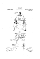
- the object 'of the invent-ion is to provide i 1:0 a new and improved cotton picker arranged to readily remove or pick the ripe bolls ot tom .of the plants upward to the top thereof.
- Figure l' is a longitudinal central section '301 of the cotton picker .on the line 11 of Fig.-
- Fig.'2 is' a front end elevation ot the same;
- F ig. 3v i's a plan view ofthe front end of the cotton picker with the receiving tube shown -in section';
- Fig. 4 is a sectional plan 3?view-o1t the same 'on the line 4--4-4 of Fig. 1;
- f Fig'. 5'1s a transverse 'section of the same on the line5-5 of Fig. l;
- Fig. 6 is a sectional planview of'the'driving gear for the air propellers';
- Fig. 7 is an enlarged transverse .section of the adjustable connection for the front end. of the support;
- Fig.'2 is' a front end elevation ot the same;
- F ig. 3v i's a plan view ofthe front end of the cotton picker with the receiving tube shown -in section';
- Fig. 4 is a sectional plan 3?view-
- Fig. 8 isy an enlarged sectional side elevation of the adjustable support for the spreader;
- Fig. 9 is an enlarged sectional .plan view of the delivery ⁇ .end of the conductingV tube for the said bolls, on the line 9 9V of Fig. l; .and Fig. 10 'is an enlarged 'cross ⁇ sect-ion of the air propeller mechanism, the sectionvbeingvon.
- the cotton picker is mount-eden a wheeled support A' adapted to be moved over. theield in-the direction yoft the arrow a by the use of a'team'ory by the employment ofmo.y
- the supportA is providedwith ftransverslyegtendinglUfshaped front and Specification of Letters Patent.
- yB is suicient to lforce the bolls rearwardly into a-bag or other receptacle D, removably held on a holder E mounted on the rear ot' ,the support A, as plainly shown in Fig. 1.
- a holder E mounted on the rear ot' ,the support A, as plainly shown in Fig. 1.
- ot' guiding wings Fand F attached to the front standard -A,the said Wings F, F converging from the front to the rear so as to readily guide the cotton plants between the members A3, A4.
- a longitudinally-extending spreader Gr Centrally above the propellers B and B is arranged a longitudinally-extending spreader Gr, approximately triangular in cross section, to engagethe cotton plants at tlie top and press the same sidewise in opposite directions with a view to extend the to insure a proper detaching et the cotton bo-lls from the plants by the air blast.
- a The spreader, G is hung on upwardly-extending tached to the support A, and pins G? (see Fig. 8) are adapted to engage apertures Gr-Jl to support kthe ⁇ latternon thetop ⁇ of ferent' apertures Gt.
- the spreader ,G1 can be the cotton plants on which used at the time.v
- the machine is cot-ton plants on oppositesides of the row.
- p (ln the members A3., A* are mounted sets ot'- The. air blast produced by the propellcrs B and.
- More or less inclinel can be given to the detlectors Il and I'I, and'for this' purpose the dcflectors II and Il" are'pivotally connected by links I and I with arms I2, I3 secured on shafts I4, lfjournaled on the. support A, and on the shaft l.4 is secured a hand lever J under the control of the operator seated on the seat l( held on the support A.
- The-hand lever J is provided with a locking device J adapted to engage u segment J2 attached to the. support A.
- the shaft I5 previously mentioned is provided with an arm I6 connected by a link I7 with the lever J so that when the latter is swung forward or backward then a.
- sprocket wheels yO On the outer ends of the shafts N4, N5 are secured sprocket wheels yO, O connected by sprocket chains O2, O3 with sprocket wheels O4, O5, secured on the outer ends of the shaft P of a motor P, of any approved construction, and
- the rear or delivery end C2 of the delivery tube C is in the form of rods spaced apart to formescape openings for the air,
- a valve Q made in two,v hinged sections is mounted on the terminal of the end C2 to permit of closing the said terminal while removing a lillcd bag D from the holder .E and placing an elupty bag in position thereon.
- the free end of the support A and the parts carried thereby can be raised and lowered, and for this purpose the following arrangement is made:
- the rear end of the support. A is provided with hangers R in which jo-urnaled the rear axle S carrying the rear wheels S,iand the front wheels S2 are journaled on the lower ends of rods T mounted to slide up and down in suitable bearings rI.”attarched to the U-shaped front standard A", as plainly indicated in Figs. 2 and 7, and the upper ends of the rods T are journaled in a. transverse bar T2 on which is fulcrumed a hand lever U- within co-nvenient reach of the operator seated on the seat K.
- the forward end of the hand lever U is pivotally connected by a link U with the forward end of the support A so that when the operator imparts an up and down swinging motion to the lever U an up and down swinging motion is given to the support A through the latter turning on the rear aXle 'S as a fulcrum.
- the lever U is locked in place by a locking device U2 mounted on the lever and engaging a 'notched segment U3 attached to the crossl bar T2.
- the operation is as follows When the ma chine is drawn forward over the field with a row of'cotton plants passing between the members A3, A4, and the motor P is running then the motion given to the propellers B and B causes an upward blast to be directed against the cotton plants'on opposite sides Afrom the kholder E thereof and in an upward direction so that the bolls are detached-froln'the cotton lplants andare blown upward and directed int-o'the mouthCf of thetufbe Cthrough which the bolls pass 'together with the air, tlielatter finally passing out through lthe spaces in the rear end C2 while the cotton bolls drop down intothe bagD.
- the cotton picker shown and described is comparatively simple in construction and arranged to eifectlvely detach the cotton bolls from the plants and collect the same in a bag.
- a cotton picker provided with air propellers arranged to pass along the lower portions of the plants and force an air blast upwardly against the bolls of cotton to detach the same, and a conducting tube above the propellers for ⁇ receiving the detached bolls of cotton.
- a cotton picker provided with sets of horizontally-disposed rotary 'air propellers spacedvapartfor the passage of the cotton plants between along the lower portions of the plants, the said air propellers being arranged to force air blasts upwardly against the bolls of cotand a conducting tube having its mouth above thepropellers for receiving the detached bolls of cotton.
- a cotton picker comprising a support having spaced longitudinal bottom members fspreadingthe plants in opposite F readily guidel them and arranged to pass betweenwhich pass the cotton plants, horil ⁇ zontally-disposed and rotary lair' propellers mounted 'on the said spaced members, and
- a cotton picker comprising a support having spaced longitudinal bottom members, ⁇ between which 'pass the cotton plants,
- a cotton picker comprising a support havingl spaced ⁇ longitudinal bottom members between which pass the cotton plants, horizontally-disposed and rotary air propellers mounted on the said spaced members, a top spreader on the said support andl centrally above the propellers for spreading the plants in opposite directions over the said propellers, and a tube on the support and having at one end a mouth arranged vcentrally above the said spreader.
- a cotton picker comprising a support having spaced'longitudinal lbottom members between which pass the cotton plants, horizontallydisposed and rotary air propellers mounted on the said spaced members, a top spreader on the said support and centrally above the propellers for spreading the plants in opposite directions over the said propellers, a tube on the supportand having at one end a mouth arranged centrally above the said spreader, and deflectors on the said support in front and rear of the said tube mouth.
- a cotton picker comprising a support having spaced longitudinal bottom members between which pass the cotton plants, horizontally-disposed and rotary air propellers mounted on the said' spaced members, a top spreader on the said support and centrally above the propellers for spreading the plants in opposite directions over the said propel-- 1ers, a tube on the support and having at one end a mouth arranged cent-rally above the said spreader, deflectors hinged on the said support in front and rear of the said tube mouth, and manually-controlled means connected with the said deflectors to swing the same into a -desired inclined position.
- a cotton picker provided with air propellers arranged to pass along the lower portions of the plants and force air blasts upwardlyv against the bolls of cotton to detach the same, a. top spreader arranged centrally above the propellers for spreading the plants'in opposite directions over the said propellers, and a conducting tube above the spreader for receiving the detached bolls of cotton.
- a cotton picker provided with air propellers spacedapart and arranged to pass along the lowerportions of the plants and force air blasts upwardly against the bolls of cotton to detach the same, aniadjustable top spreader arranged centrally above the propellers for spreading the plants in opposite directions over the said air propellers,
- a cotton picker comprising .a sup port having spaced longitudinal bottom members between which pass the lower portions of the cotton plants, sets of horizontally-disposed air propellers mounted to rotate on thevsaid members, gearings for driving the said sets of propellers in unison, guide members attached to the said support in front of the said propellers, a tube extending rearwardly on thesaid support and havlng a mouth centrally arranged above the said propellers, a spreader held vertically adjustable on the said support below the said tube mouth,l delectors hinged on the said support in front and rear of the said tube mouth, and manually-controlled Ameans eonnet'td'with thlesaid'deflectors to 'adjust thesfame'.
- a cotton' picker',- comprising a support having-spaced longitudinal bottom membersl between which passthe cotton plants, horizontally. disposed v'and rotary .air propellers mounted on the said spaced members, means for driving the propellers in unison, a longitudinally extending spreader adjustably connected ywith the support and arranged centrally above the said propellers, the said spreader being approximately triangular in cross section and arranged'to spread the plants in opposite directions over thesaid prcpellers, a ytube on the support and .having at one end a mouth arranged centrally above the said spreader, and deflectors on the said support for directing the detached cotton bolls to the mouth of said tube..
Landscapes
- Life Sciences & Earth Sciences (AREA)
- Environmental Sciences (AREA)
- Catching Or Destruction (AREA)
Description
H. SKAER.
COTTON PICKER.
APPLICATION FILED DB0. 16, 1911.
Patented Aug. 20, 1912.
3 SHEETS-SHEET Z.
H. 'SKAER.
COTTON PICKER.
APPLICATION FILED 1320.16, 1911.
W/T/VESSES vgy'nn STATES: natuur N oFFioE.:
HENRY SKAER, oF T'AiifiARoA, ILLINOIS.
COTTON-tionen..
Application flied December I To-allwhom t may concern Be itknown that-I, HENRY Simian,l a
citizen of the United States, and a residentV of Tamaroa, in the county of Perry and State of Illinois, have invented a new 'and' Improved Cotton-Picker, of which the following is a full, clear, and exact description.
The object 'of the invent-ion is to provide i 1:0 a new and improved cotton picker arranged to readily remove or pick the ripe bolls ot tom .of the plants upward to the top thereof.
For the purpose mentioned, use is made of air propellers arranged'to pass along the lower portions of the plants and forcing an 29C air blast upwardly against the bolls of cotton to detach the same from the plants, and
a conducting tube above the plants tor receivingthe detached bolls of cotton. y
A practicalembodiment of the invention is represented'in'the accompanying drawings forming a part of this specification, in
which similar characters 'of reference indicatecorresponding parts in all the views.
Figure l'is a longitudinal central section '301 of the cotton picker .on the line 11 of Fig.-
2; Fig.'2 is' a front end elevation ot the same; F ig. 3v i's a plan view ofthe front end of the cotton picker with the receiving tube shown -in section'; Fig. 4 is a sectional plan 3?view-o1t the same 'on the line 4--4-4 of Fig. 1; f Fig'. 5'1s a transverse 'section of the same on the line5-5 of Fig. l; Fig. 6 is a sectional planview of'the'driving gear for the air propellers'; Fig. 7 is an enlarged transverse .section of the adjustable connection for the front end. of the support; Fig. 8 isy an enlarged sectional side elevation of the adjustable support for the spreader; Fig. 9 is an enlarged sectional .plan view of the delivery `.end of the conductingV tube for the said bolls, on the line 9 9V of Fig. l; .and Fig. 10 'is an enlarged 'cross `sect-ion of the air propeller mechanism, the sectionvbeingvon.
the line# 10-10 -of Fig-l. j w The cotton picker is mount-eden a wheeled support A' adapted to be moved over. theield in-the direction yoft the arrow a by the use of a'team'ory by the employment ofmo.y
tivevpower. -The supportA is providedwith ftransverslyegtendinglUfshaped front and Specification of Letters Patent.
l Patented Aug.20,1912. 1s, 1911. serial ne.. 666,142.
rear supports A', A2 supporting at their lower ends' longitudinal members 'A3, A* spaced apart to permit the passage ot' the cotton plants between the said members. the I,latter being near the ground so as to pass i'close to the lower portions of the row of 'air propellers B *and4 B -in the form ofhoriwlien the wheels are rotated theyproduce currents ofair flowing in an upward direction against the bolls of cotton held on the plants to det/ach the bolls from the plants and force the same upward into the mouth i C of a conducting'tube C arranged on the top of the support A and extend-ing reari wardly, as plainly indicated in Fig. 1.
yB is suicient to lforce the bolls rearwardly into a-bag or other receptacle D, removably held on a holder E mounted on the rear ot' ,the support A, as plainly shown in Fig. 1. In order to properly guide the cotton plants tothe narrowspace between the members A3 and A4 of the support A, use is made ot' guiding wings Fand F attached to the front standard -A,the said Wings F, F converging from the front to the rear so as to readily guide the cotton plants between the members A3, A4.
Centrally above the propellers B and B is arranged a longitudinally-extending spreader Gr, approximately triangular in cross section, to engagethe cotton plants at tlie top and press the same sidewise in opposite directions with a view to extend the to insure a proper detaching et the cotton bo-lls from the plants by the air blast. A The spreader, G is hung on upwardly-extending tached to the support A, and pins G? (see Fig. 8) are adapted to engage apertures Gr-Jl to support kthe `latternon thetop `of ferent' apertures Gt. the spreader ,G1 can be the cotton plants on which used at the time.v
the detached cotton bolls tothe month yCy vof zontally-disposed propeller wheels so that arrangedin theupper ends of; the rods G" the bearf-y ing G2. By engaging the pins G? with dif- Y raised orlowered according-tothe height of i105.,
'the machine is cot-ton plants on oppositesides of the row. p (ln the members A3., A* are mounted sets ot'- The. air blast produced by the propellcrs B and.
through the tube Cto be finally discharged plants over the sets of air propellers B, BI l rods G slidably engaging bearings G-atl In order. to ,-insurefthed` passage of icctorsfll .andiI'If pivoted I'I2, II3 on thek support A in front and rear lof the mouth C', as plainly indicated in Fig. l.- The delict-tors Il and II are held in inclined positions and convergetoward the mouth C', ,so that the detached' cotton bolls which are forccd'upward by the air .blast and strike the deflectors II, H are deflected by the latter in an upward direction into the mouth C of the conducting-tube C. More or less inclinel can be given to the detlectors Il and I'I, and'for this' purpose the dcflectors II and Il" are'pivotally connected by links I and I with arms I2, I3 secured on shafts I4, lfjournaled on the. support A, and on the shaft l.4 is secured a hand lever J under the control of the operator seated on the seat l( held on the support A. The-hand lever J is provided with a locking device J adapted to engage u segment J2 attached to the. support A. The shaft I5 previously mentioned is provided with an arm I6 connected by a link I7 with the lever J so that when the latter is swung forward or backward then a. corresponding turning movement given to the shafts I4, I5. which by the arms I2. I3 and the links I. I impart a downward or upward swinging movement to the deflectors I-l and H. and when the desired position is reached the lever J is locked in place by the locking device J -to hold the deflectors H and H locked in adjusted posit-ion.
In order to rotate the horizontally dis posed propellers in unison, the following arrangement is made: On the shafts B2, B3 of the propeliers B, B are secured pinions L and L in mesh with gear wheels L2, L3 journaled on the members A3, A4, and on the top of the forward gear wheels L2, L3 are secured bevel gea-r wheels N, N (see Fig. 10) in mesh with bevel gear wheels N2. N3 secured on transversely-extending shafts N4, N5 journaled in suitable bearings attached to the upper side of the vmembers A3, A4. On the outer ends of the shafts N4, N5 are secured sprocket wheels yO, O connected by sprocket chains O2, O3 with sprocket wheels O4, O5, secured on the outer ends of the shaft P of a motor P, of any approved construction, and
mounted ont-he support A, as plainly indicated in Figs'. 1 and 5. When the motor P is running the shafts N4, N are rotated and by the bevel gear wheelsNZ, N and N3, N rotate vthe corresponding gear wheels L2, L3
Iwhereby ro'tary motion is transmitted to the severalpropellers B and B by the gearing described, so that the said propellers B and B' are rotated in unison to produce air currents orblasts for det-aching the bolls from4 Vthe `plants and forcing the bolls. into andthrough `the' tube C.
The rear or delivery end C2 of the delivery tube C is in the form of rods spaced apart to formescape openings for the air,
the end C2 being curved downwardly to readily 'discharge the cotton bolls into the bag Dbsupported on the holder A valve Q, made in two,v hinged sections is mounted on the terminal of the end C2 to permit of closing the said terminal while removing a lillcd bag D from the holder .E and placing an elupty bag in position thereon.
The free end of the support A and the parts carried thereby can be raised and lowered, and for this purpose the following arrangement is made: The rear end of the support. A is provided with hangers R in which jo-urnaled the rear axle S carrying the rear wheels S,iand the front wheels S2 are journaled on the lower ends of rods T mounted to slide up and down in suitable bearings rI."attarched to the U-shaped front standard A", as plainly indicated in Figs. 2 and 7, and the upper ends of the rods T are journaled in a. transverse bar T2 on which is fulcrumed a hand lever U- within co-nvenient reach of the operator seated on the seat K. The forward end of the hand lever U is pivotally connected by a link U with the forward end of the support A so that when the operator imparts an up and down swinging motion to the lever U an up and down swinging motion is given to the support A through the latter turning on the rear aXle 'S as a fulcrum. After the support A has been raised or lowered at its front end to the desired height above the ground then the lever U is locked in place by a locking device U2 mounted on the lever and engaging a 'notched segment U3 attached to the crossl bar T2.
Inorder to enable the operator to steer the front 'wheels S2 in the desired direction. use is made of the following steering device: On the upper ends of the rods T are secured rearwardly extending arms T3 pivotally 'connected with a transversely-extending rack V mounted to slide transversely`in a` suitable bearing V attached to the support. A. The rack V is engaged by a pinion V2 secured on a shaft V3 journaled in suitable bearings carried by the cross bar T2.and the bearing V, and on the rear end of the shaft V3 "is secured a hand wheel V* under the control of the opera-tor seated on the seat K. Thus when the operator turns the hand wheel V4` the pinion V2 shifts the rack V transversely to the right or to the left, thus imparting a corresponding swinging motion to the arms T3 whereby the rods T are turned to' cause the front wheels S2 to travel in the desired direction to the right orto th left or straight ahead.
The operation is as follows When the ma chine is drawn forward over the field with a row of'cotton plants passing between the members A3, A4, and the motor P is running then the motion given to the propellers B and B causes an upward blast to be directed against the cotton plants'on opposite sides Afrom the kholder E thereof and in an upward direction so that the bolls are detached-froln'the cotton lplants andare blown upward and directed int-o'the mouthCf of thetufbe Cthrough which the bolls pass 'together with the air, tlielatter finally passing out through lthe spaces in the rear end C2 while the cotton bolls drop down intothe bagD. When 'the bag D is filled the valve" Q is closed for the, time being to permit ofmrelmoving the filled bag and placing an' empty bag in position thereon, after which the valve Q is again opened so as toll the bag with cotton bolls. Itis understood that during the forward movement of the machine, the guide wings F, the cotton plants between the members A3, A4 so that the branches of the cotton plants overhang the propellers B, Bv and the spreader G by coming in contact withl the top,of the plants turns the upper portions thereof outwardly so that the branches are all subjected to the air currents or blasts emanating from the propellers B and B', and consequently the ripe bolls .are readily detached from the plants and forced upward into and through the tube C. As it is well known that cotton bolls ripen from the bottom of the plants upward, it is evident that the machine has to be drawn several times over a row of cotton plants to gather all the bolls, that is, during 'the first movement of the machine over a row of cotton plants, the lower-most ripe bolls are detached and gathered, and at the following operations the'bolls higher up are detached and harvested in the manner above eX- plained.
The cotton picker shown and described is comparatively simple in construction and arranged to eifectlvely detach the cotton bolls from the plants and collect the same in a bag.
tonto. detach the same,
Having thus described my invention, I
claim as new and desire to secure by Letters Patent '1. A cotton picker provided with air propellers arranged to pass along the lower portions of the plants and force an air blast upwardly against the bolls of cotton to detach the same, and a conducting tube above the propellers for `receiving the detached bolls of cotton.
2. A cotton picker provided with sets of horizontally-disposed rotary 'air propellers spacedvapartfor the passage of the cotton plants between along the lower portions of the plants, the said air propellers being arranged to force air blasts upwardly against the bolls of cotand a conducting tube having its mouth above thepropellers for receiving the detached bolls of cotton.
3. A cotton picker, comprising a support having spaced longitudinal bottom members fspreadingthe plants in opposite F readily guidel them and arranged to pass betweenwhich pass the cotton plants, horil `zontally-disposed and rotary lair' propellers mounted 'on the said spaced members, and
guiding: means on the support in front of the propellers for'guiding the plants to the said propellers.
'4. A cotton picker, comprising a support having spaced longitudinal bottom members, `between which 'pass the cotton plants,
y,horizontally-disposed and rotary air propellers mounted on the said spaced members, anda top spreader-on the said supportand Vcentrally above the propellers for directions over the said propellers.
5. A cotton picker, comprising a support havingl spaced` longitudinal bottom members between which pass the cotton plants, horizontally-disposed and rotary air propellers mounted on the said spaced members, a top spreader on the said support andl centrally above the propellers for spreading the plants in opposite directions over the said propellers, and a tube on the support and having at one end a mouth arranged vcentrally above the said spreader.
6. A cotton picker, comprising a support having spaced'longitudinal lbottom members between which pass the cotton plants, horizontallydisposed and rotary air propellers mounted on the said spaced members, a top spreader on the said support and centrally above the propellers for spreading the plants in opposite directions over the said propellers, a tube on the supportand having at one end a mouth arranged centrally above the said spreader, and deflectors on the said support in front and rear of the said tube mouth.
7 A cotton picker, comprising a support having spaced longitudinal bottom members between which pass the cotton plants, horizontally-disposed and rotary air propellers mounted on the said' spaced members, a top spreader on the said support and centrally above the propellers for spreading the plants in opposite directions over the said propel-- 1ers, a tube on the support and having at one end a mouth arranged cent-rally above the said spreader, deflectors hinged on the said support in front and rear of the said tube mouth, and manually-controlled means connected with the said deflectors to swing the same into a -desired inclined position.
8. A cotton picker provided with air propellers arranged to pass along the lower portions of the plants and force air blasts upwardlyv against the bolls of cotton to detach the same, a. top spreader arranged centrally above the propellers for spreading the plants'in opposite directions over the said propellers, and a conducting tube above the spreader for receiving the detached bolls of cotton.
9. A cotton picker provided with air propellers spacedapart and arranged to pass along the lowerportions of the plants and force air blasts upwardly against the bolls of cotton to detach the same, aniadjustable top spreader arranged centrally above the propellers for spreading the plants in opposite directions over the said air propellers,
and a tube having at one end a. mouth arranged centrally above the spreader, the said tube havin its otherend constructed for the escape cig air.
l0. A cotton picker, comprising .a sup port having spaced longitudinal bottom members between which pass the lower portions of the cotton plants, sets of horizontally-disposed air propellers mounted to rotate on thevsaid members, gearings for driving the said sets of propellers in unison, guide members attached to the said support in front of the said propellers, a tube extending rearwardly on thesaid support and havlng a mouth centrally arranged above the said propellers, a spreader held vertically adjustable on the said support below the said tube mouth,l delectors hinged on the said support in front and rear of the said tube mouth, and manually-controlled Ameans eonnet'td'with thlesaid'deflectors to 'adjust thesfame'. -l A "l y 11. A cotton' picker',- comprising a support having-spaced longitudinal bottom membersl between which passthe cotton plants, horizontally. disposed v'and rotary .air propellers mounted on the said spaced members, means for driving the propellers in unison, a longitudinally extending spreader adjustably connected ywith the support and arranged centrally above the said propellers, the said spreader being approximately triangular in cross section and arranged'to spread the plants in opposite directions over thesaid prcpellers, a ytube on the support and .having at one end a mouth arranged centrally above the said spreader, and deflectors on the said support for directing the detached cotton bolls to the mouth of said tube..
In testimony whereof- I'have signed my name to this 'specification in the presence of two subscribing witnesses.
HENRY SKAER.
Y Witnesses:
S. R. HAINES, M. WHEATLEY.
Priority Applications (1)
| Application Number | Priority Date | Filing Date | Title |
|---|---|---|---|
| US66614211A US1036357A (en) | 1911-12-16 | 1911-12-16 | Cotton-picker. |
Applications Claiming Priority (1)
| Application Number | Priority Date | Filing Date | Title |
|---|---|---|---|
| US66614211A US1036357A (en) | 1911-12-16 | 1911-12-16 | Cotton-picker. |
Publications (1)
| Publication Number | Publication Date |
|---|---|
| US1036357A true US1036357A (en) | 1912-08-20 |
Family
ID=3104636
Family Applications (1)
| Application Number | Title | Priority Date | Filing Date |
|---|---|---|---|
| US66614211A Expired - Lifetime US1036357A (en) | 1911-12-16 | 1911-12-16 | Cotton-picker. |
Country Status (1)
| Country | Link |
|---|---|
| US (1) | US1036357A (en) |
Cited By (3)
| Publication number | Priority date | Publication date | Assignee | Title |
|---|---|---|---|---|
| US2514898A (en) * | 1949-03-08 | 1950-07-11 | William E Ramsey | Combination cotton picker and insect catcher |
| US2576381A (en) * | 1945-11-30 | 1951-11-27 | Lemuel T Wright | Cotton stripper |
| US2674078A (en) * | 1949-08-13 | 1954-04-06 | Frederick W Stukenborg | Cotton harvester |
-
1911
- 1911-12-16 US US66614211A patent/US1036357A/en not_active Expired - Lifetime
Cited By (3)
| Publication number | Priority date | Publication date | Assignee | Title |
|---|---|---|---|---|
| US2576381A (en) * | 1945-11-30 | 1951-11-27 | Lemuel T Wright | Cotton stripper |
| US2514898A (en) * | 1949-03-08 | 1950-07-11 | William E Ramsey | Combination cotton picker and insect catcher |
| US2674078A (en) * | 1949-08-13 | 1954-04-06 | Frederick W Stukenborg | Cotton harvester |
Similar Documents
| Publication | Publication Date | Title |
|---|---|---|
| US3077720A (en) | Tree fruit harvester | |
| US1722747A (en) | Cotton harvester | |
| US2780904A (en) | Nut pickup device | |
| US2111030A (en) | Agricultural machine | |
| US2935957A (en) | Bulb planter | |
| US2427313A (en) | Cane piler | |
| US2489963A (en) | Cotton picker | |
| US1275781A (en) | Cotton-harvester. | |
| US2175216A (en) | Self-propelled tandem cotton picking machine | |
| US1233089A (en) | Cranberry-harvesting apparatus. | |
| US2520927A (en) | Cotton-picking apparatus | |
| US3100368A (en) | Apparatus for recovering cotton from the ground | |
| US1945119A (en) | Corn picker | |
| US2689439A (en) | Cotton harvester | |
| US2798351A (en) | Pneumatic cotton harvester with gyrating picking fingers | |
| US2500441A (en) | Bean stacker | |
| US2558894A (en) | Potato harvester and cleaner | |
| US1751376A (en) | Cotton picker | |
| US1389789A (en) | Potato-picker | |
| US775451A (en) | Cotton-picking machine. | |
| US1134158A (en) | Cotton-picking machine. | |
| US1784702A (en) | Cranberry gatherer | |
| US1252016A (en) | Cotton-picker. | |
| US1004835A (en) | Cotton-picker. | |
| US992960A (en) | Cotton-picking machine. |