US10348919B2 - Covering structure for cable - Google Patents
Covering structure for cable Download PDFInfo
- Publication number
- US10348919B2 US10348919B2 US15/976,841 US201815976841A US10348919B2 US 10348919 B2 US10348919 B2 US 10348919B2 US 201815976841 A US201815976841 A US 201815976841A US 10348919 B2 US10348919 B2 US 10348919B2
- Authority
- US
- United States
- Prior art keywords
- electronic module
- shaft
- cover
- cable
- covering structure
- Prior art date
- Legal status (The legal status is an assumption and is not a legal conclusion. Google has not performed a legal analysis and makes no representation as to the accuracy of the status listed.)
- Active
Links
- 230000002093 peripheral effect Effects 0.000 claims description 24
- 238000000034 method Methods 0.000 claims description 3
- 230000002633 protecting effect Effects 0.000 description 7
- 230000008901 benefit Effects 0.000 description 2
- 230000000694 effects Effects 0.000 description 2
- 238000005516 engineering process Methods 0.000 description 2
- 238000012986 modification Methods 0.000 description 2
- 230000004048 modification Effects 0.000 description 2
- 238000007639 printing Methods 0.000 description 2
- 238000005452 bending Methods 0.000 description 1
- 230000002708 enhancing effect Effects 0.000 description 1
- 230000003068 static effect Effects 0.000 description 1
Images


Classifications
-
- H—ELECTRICITY
- H04—ELECTRIC COMMUNICATION TECHNIQUE
- H04N—PICTORIAL COMMUNICATION, e.g. TELEVISION
- H04N1/00—Scanning, transmission or reproduction of documents or the like, e.g. facsimile transmission; Details thereof
- H04N1/00519—Constructional details not otherwise provided for, e.g. housings, covers
- H04N1/00551—Top covers or the like
- H04N1/00554—Latches or hinges therefor
-
- B—PERFORMING OPERATIONS; TRANSPORTING
- B41—PRINTING; LINING MACHINES; TYPEWRITERS; STAMPS
- B41J—TYPEWRITERS; SELECTIVE PRINTING MECHANISMS, i.e. MECHANISMS PRINTING OTHERWISE THAN FROM A FORME; CORRECTION OF TYPOGRAPHICAL ERRORS
- B41J29/00—Details of, or accessories for, typewriters or selective printing mechanisms not otherwise provided for
- B41J29/12—Guards, shields or dust excluders
- B41J29/13—Cases or covers
-
- B—PERFORMING OPERATIONS; TRANSPORTING
- B41—PRINTING; LINING MACHINES; TYPEWRITERS; STAMPS
- B41J—TYPEWRITERS; SELECTIVE PRINTING MECHANISMS, i.e. MECHANISMS PRINTING OTHERWISE THAN FROM A FORME; CORRECTION OF TYPOGRAPHICAL ERRORS
- B41J29/00—Details of, or accessories for, typewriters or selective printing mechanisms not otherwise provided for
- B41J29/38—Drives, motors, controls or automatic cut-off devices for the entire printing mechanism
- B41J29/393—Devices for controlling or analysing the entire machine ; Controlling or analysing mechanical parameters involving printing of test patterns
-
- H—ELECTRICITY
- H02—GENERATION; CONVERSION OR DISTRIBUTION OF ELECTRIC POWER
- H02G—INSTALLATION OF ELECTRIC CABLES OR LINES, OR OF COMBINED OPTICAL AND ELECTRIC CABLES OR LINES
- H02G11/00—Arrangements of electric cables or lines between relatively-movable parts
-
- H—ELECTRICITY
- H04—ELECTRIC COMMUNICATION TECHNIQUE
- H04N—PICTORIAL COMMUNICATION, e.g. TELEVISION
- H04N1/00—Scanning, transmission or reproduction of documents or the like, e.g. facsimile transmission; Details thereof
- H04N1/0083—Arrangements for transferring signals between different components of the apparatus, e.g. arrangements of signal lines or cables
-
- H05K5/0021—
-
- H—ELECTRICITY
- H05—ELECTRIC TECHNIQUES NOT OTHERWISE PROVIDED FOR
- H05K—PRINTED CIRCUITS; CASINGS OR CONSTRUCTIONAL DETAILS OF ELECTRIC APPARATUS; MANUFACTURE OF ASSEMBLAGES OF ELECTRICAL COMPONENTS
- H05K5/00—Casings, cabinets or drawers for electric apparatus
- H05K5/02—Details
- H05K5/0217—Mechanical details of casings
- H05K5/0226—Hinges
-
- H—ELECTRICITY
- H05—ELECTRIC TECHNIQUES NOT OTHERWISE PROVIDED FOR
- H05K—PRINTED CIRCUITS; CASINGS OR CONSTRUCTIONAL DETAILS OF ELECTRIC APPARATUS; MANUFACTURE OF ASSEMBLAGES OF ELECTRICAL COMPONENTS
- H05K5/00—Casings, cabinets or drawers for electric apparatus
- H05K5/02—Details
- H05K5/0247—Electrical details of casings, e.g. terminals, passages for cables or wiring
-
- H—ELECTRICITY
- H05—ELECTRIC TECHNIQUES NOT OTHERWISE PROVIDED FOR
- H05K—PRINTED CIRCUITS; CASINGS OR CONSTRUCTIONAL DETAILS OF ELECTRIC APPARATUS; MANUFACTURE OF ASSEMBLAGES OF ELECTRICAL COMPONENTS
- H05K5/00—Casings, cabinets or drawers for electric apparatus
- H05K5/02—Details
- H05K5/03—Covers
-
- H—ELECTRICITY
- H05—ELECTRIC TECHNIQUES NOT OTHERWISE PROVIDED FOR
- H05K—PRINTED CIRCUITS; CASINGS OR CONSTRUCTIONAL DETAILS OF ELECTRIC APPARATUS; MANUFACTURE OF ASSEMBLAGES OF ELECTRICAL COMPONENTS
- H05K5/00—Casings, cabinets or drawers for electric apparatus
- H05K5/30—Side-by-side or stacked arrangements
Definitions
- the disclosure is related to a covering structure for cable.
- peripheral machines or office machine or multi-function printer (MFP)
- MFP multi-function printer
- peripheral machines that serve the above-mentioned functions are generally combined via modules stacked together. Therefore, when using this type of peripheral machines, it is required to open the cover (to be in an unfolded state) or close the cover on a base, or open one of the electronic modules or close it on another electronic module.
- the disclosure provides a covering structure for cable which is capable of providing covering and protecting effect for cable in the process of opening/closing an electronic module.
- the covering structure for cable is adaptable for connecting between a first electronic module and a second electronic module.
- the first electronic module is adaptable for being pivoted relative to the second electronic module to be opened/closed.
- the first electronic module and the second electronic module are electrically connected via a cable; when the first electronic module is pivoted relative to the second electronic module to be opened, a portion of the cable is exposed outside the first electronic module and the second electronic module.
- the covering structure for cable includes a cover, a first shaft and a second shaft.
- the first shaft is disposed on one side of the cover, and the cover is pivoted to the first electronic module via the first shaft.
- the second shaft is disposed on another side of the cover relative to the first shaft, and the cover is movably pivoted to the second electronic module via the second shaft.
- the cover is driven via the first shaft and the second shaft such that the cover covers the portion of the cable exposed outside the first electronic module and the second electronic module when the first electronic module is opened relative to the second electronic module.
- the covering structure for cable consists of at least one cover, the first shaft and the second shaft, wherein the cover is pivoted to the first electronic module via the first shaft, and the cover is movably pivoted to the second electronic module via the second shaft; therefore, the cover is driven at the same time when the first electronic module is pivoted relative to the second electronic module to be opened/closed. Accordingly, when the first electronic module is opened (or unfolded) relative to the second electronic module, the cable that is electrically connected between the first electronic module and the second electronic module is exposed. Nevertheless, since the cover is driven at the same time, the portion of the cable that is exposed can be covered. In this manner, the cover is capable of providing the covering and protecting function for the appearance of cable so as to prolong the service life of the cable as well as enhance appearance of the electronic module.
- FIG. 1 is a schematic view of a peripheral machine according to an embodiment of the disclosure.
- FIG. 2 is a schematic view illustrating another state of a portion of the structure of the peripheral machine in FIG. 1 .
- FIG. 3 is an enlargement view of a partial structure of the peripheral machine in FIG. 1 .
- FIG. 4 and FIG. 5 are schematic views respectively illustrating a portion of components of the peripheral machines in FIG. 1 and FIG. 2 .
- FIG. 6 and FIG. 7 are side views respectively illustrating the peripheral machines in FIG. 1 and FIG. 2 .
- FIG. 8 and FIG. 9 are side views respectively illustrating a covering structure for cable according to another embodiment of the disclosure.
- FIG. 1 is a schematic view of a peripheral machine according to an embodiment of the disclosure.
- FIG. 2 is a schematic view illustrating another state of a portion of the structure of the peripheral machine in FIG. 1 .
- FIG. 3 is an enlargement view of a partial structure of the peripheral machine in FIG. 1 .
- a Cartesian coordinate X-Y-Z is provided in some of the drawings for ease of illustration of related components.
- a peripheral machine 100 includes a base 130 , a first electronic module 110 and a second electronic module 120 stacked on the base 130 , wherein the first electronic module 110 is, for example, an automatic document feeder (ADF) of the peripheral machine 100 , and the second electronic module 120 may be a scanner or a copy machine of the peripheral machine 100 , and the base 130 may be provided with a medium (e.g., paper) accommodating space and a printer module (not shown) therein so as to cooperate with the first electronic module 110 and the second electronic module 120 to perform various peripheral functions such as making copies, printing, scanning and so on; all of the functions can be derived from known technologies and thus no further descriptions are incorporated herein.
- ADF automatic document feeder
- the second electronic module 120 is substantially fixed on the base 130 , and the first electronic module 110 is capable of being substantially pivoted relative to the second electronic module 120 along a pivotal axial direction so as to achieve the effect that the first electronic module 110 can be opened (unfolded)/closed (folded) relative to the second electronic module 120 .
- the first electronic module 110 as an ADF is regarded as a dynamic object
- the second electronic module 120 as a scanner is regarded as a static object.
- the second electronic module 120 has a supporting plane.
- the supporting plane of the second electronic module 120 may be substantially regarded as an X-Y plane.
- at least one hinge is connected between the first electronic module 110 and the second electronic module 120 .
- the first electronic module 110 is pivoted relative to the second electronic module 120 along the pivotal axial direction (which may be regarded as X-axis) via the hinges 150 and 160 so as to achieve the required opening/closing state.
- the hinges 150 and 160 not only enable the first electronic module 110 and the second electronic module 120 to be pivoted relative to each other, the structure (not shown) thereof also provides a supporting force so that the first electronic module 110 can be maintained in an opening state (as shown in FIG. 2 ) and to maintain opened at a random angle.
- the first electronic module 110 is closed on the second electronic module 120 , the first electronic module 110 substantially leans against the supporting plane, i.e., the X-Y plane.
- FIG. 4 and FIG. 5 are schematic views respectively illustrating a portion of components of the peripheral machines in FIG. 1 and FIG. 2 for describing the feature of related components in the pivotal axial direction, wherein FIG. 4 is illustrated in corresponding to the states shown in FIG. 1 and FIG. 3 , and FIG. 5 is illustrated in corresponding to the state in FIG. 2 .
- the first electronic module 110 and the second electronic module 120 are electrically connected with each other via a cable 170 , and thus electrically connected to a control system (not shown) of the peripheral machine 100 so as to achieve the above-mentioned functions.
- the hinges 150 and 160 are configured to provide the supporting force required by the first electronic module 110 , the hinges are closely configured in structure (compact structure) and there is no sufficient space for the cable 170 to pass through.
- the cable 170 passes through the force-receiving structure region such as hinges 150 and 160 , there is a risk that the cable 170 might be damaged due to being subjected to the force indirectly. Therefore, in the technical field related to the peripheral machine 100 , it is not likely to take the risk of letting the cable 170 that is electrically connected between the electronic modules 110 and 120 to be configured in the manner of passing through the hinges 150 and 160 .
- the designer substantially would dispose the cable 170 at a position different from the hinges 150 and 160 on the peripheral machine 100 .
- the peripheral machine 100 in the embodiment further includes a covering structure for cable 140 which includes a cover and a plurality of shafts for providing a covering and protecting effect for the portion of the cable 170 that is exposed.
- the covering structure for cable 140 may be regarded as being disposed between the first electronic module 110 and the second electronic module 120 of the peripheral machine 100 at a position different from the hinges 150 and 160 .
- the covering structure for cable 140 includes a first cover 141 , a second cover 142 , a first shaft L 1 , a second shaft L 2 and a third shaft L 3 , wherein the first cover 141 is pivoted to the first electronic module 110 via the first shaft L 1 , the second cover 142 is movably pivoted to the second electronic module 120 via the second shaft L 2 , and the first cover 141 and the second cover 142 are pivoted together via the third shaft L 3 . As shown in FIG. 4 and FIG.
- the first shaft L 1 , the second shaft L 2 and the third shaft L 3 are parallel with each other (all of them are parallel with X-axis); therefore, looking from a side viewing angle, they may be regarded as a linkage structure.
- the first shaft L 1 is substantially disposed on the first cover 141 so as for the first cover 141 to be pivoted to the first electronic module 110 ;
- the second shaft L 2 is substantially disposed on the second cover 142 so as for the second cover 142 to be movably pivoted to the second electronic module 120 ;
- the third shaft L 3 is substantially disposed on the second cover 142 so as for the second cover 142 to be pivoted to the first cover 110 .
- the embodiment provides no limitation to the configuration of the shafts.
- first shaft L 1 , the second shaft L 2 and the third shaft L 3 are disposed on the first cover 110 , the second cover 120 or the first electronic module 110 , the second electronic module 120 can be changed as appropriate depending on the needs.
- first shaft L 1 is pivoted to the first electronic module 110 in a fixed manner (not movable)
- second shaft L 2 is movably pivoted to the second electronic module 120
- the “pivoted in a fixed manner” refers to that there is no room for movement at the position where the components are pivoted together.
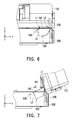
- FIG. 6 and FIG. 7 are side views respectively illustrating the peripheral machines in FIG. 1 and FIG. 2 .
- the second electronic module 120 has a recess 122 and a track 124 disposed in the recess 122 , wherein the track 124 is substantially parallel with the supporting plane (X-Y plane) of the second electronic module 120 , and the track 124 is lower than the supporting plane and has a stage.
- the second cover 142 is substantially driven accordingly to be moved into the recess 122 as shown in FIG. 6 .
- the first electronic module 110 drives the first cover 141 and also brings the second cover 120 such that the second cover 142 is lifted from the recess 122 .
- the first cover 141 and the second cover 142 are driven so that the covering and protecting functions for the cable 170 can be provided smoothly. That is, in the state shown in FIG. 2 , the cable 170 is still hidden behind the first electronic module 110 and the second electronic module 120 as well as the first cover 141 and the second cover 142 , and the user does not see the cable 170 directly.
- an orthogonal projection of the first shaft L 1 on the supporting plane, an orthogonal projection of the second shaft L 2 on the supporting plane and an orthogonal projection of the pivotal axial direction (i.e., X-axis mentioned above) of the first electronic module 110 and the second electronic module 120 on the supporting plane are respectively perpendicular to an orthogonal projection of the track 124 on the supporting plane.
- the first cover 141 is driven by the first electronic module 110 to be stacked on the second cover 142 .
- the bending state of the first cover 141 and the second cover 142 shown in FIG. 4 allows the third shaft L 3 to provide a force F to help the cable 170 to be bended so it is easy for the cable 170 to be received.
- the cover (including the first cover 141 and the second cover 142 ) of the covering structure for cable 140 is a driven element that is driven by the first electronic module 110 and the second electronic module 120 without any force-receiving or force-applying function (relative to the first electronic module 110 and the second electronic module 120 ).
- FIG. 8 and FIG. 9 are side views respectively illustrating a covering structure for cable according to another embodiment of the disclosure, which are similar to the states shown in FIG. 6 and FIG. 7 . Therefore, the same components or structural feature are not repeated herein.
- the covering structure for cable in the embodiment merely includes a single cover 210 which is pivoted to the first electronic module 110 in a fixed manner via a first shaft L 1 a , and movably pivoted to the second electronic module 120 via a second shaft L 2 a.
- the second electronic module 120 in the embodiment similarly has a recess and a track 212 disposed in the recess, and the track 212 is inclined relative to the supporting plane (the same as the X-Y plane described in the previous embodiment) of the second electronic module 120 ; meanwhile, the track 212 is extended into the second electronic module 120 from the supporting plane.
- the track 212 has a first end adjacent to the supporting plane and a second end located in (the recess) of the second electronic module 120 , wherein an orthogonal projection of the first end on the supporting plane is farther from the pivotal axial direction than an orthogonal projection of the second end on the supporting plane is.
- the inclining direction of the track 212 is extended and inclined toward the hinges 150 and 160 from the supporting plane of the second electronic module 120 , and the track 212 is substantially an inclined plane such that the second shaft L 2 a can simply lean against and move back and forth on the inclined plane, thereby achieving the movement effect that the second shaft L 2 a can be moved and pivoted.
- the embodiment uses the one-piece cover 210 that is rigid and unfoldable and driven by the first electronic module 110 to be lifted from the recess of the second electronic module 120 to provide the covering and protecting effects to the cable 170 .
- the covering structure for cable consists of at least one cover, the first shaft and the second shaft, wherein the cover is pivoted to the first electronic module via the first shaft, the cover is also movably pivoted to the second electronic module via the second shaft. Therefore, the cover is driven at the same time while the first electronic module is pivoted relative to the second electronic module to be opened/closed. Accordingly, when the first electronic module is opened relative to the second electronic module, the cable that is electrically connected between the first electronic module and the second electronic module is exposed; nevertheless, since the cover is driven at the same time, the portion of the cable that is exposed can be covered. In this manner, the cover is capable of providing covering and protecting functions for the appearance of the cable, thereby improving the service life of the cable and enhancing appearance of the electronic module.
- the at least one cover further includes the first cover and the second cover that are pivoted to each other, wherein the first cover is pivoted to the first electronic module in a fixed manner via the first shaft, and the second cover is movably pivoted to the second electronic module via the second shaft, thereby forming a two-piece linkage structure, which can similarly provide the covering and protecting functions for the cable smoothly like the one-piece rigid cover.
Landscapes
- Engineering & Computer Science (AREA)
- Microelectronics & Electronic Packaging (AREA)
- Multimedia (AREA)
- Signal Processing (AREA)
- Casings For Electric Apparatus (AREA)
- Facsimiles In General (AREA)
- Electrophotography Configuration And Component (AREA)
Abstract
Description
Claims (12)
Applications Claiming Priority (3)
| Application Number | Priority Date | Filing Date | Title |
|---|---|---|---|
| TW106132490 | 2017-09-21 | ||
| TW106132490A | 2017-09-21 | ||
| TW106132490A TWI696030B (en) | 2017-09-21 | 2017-09-21 | Covering structure for cable |
Publications (2)
| Publication Number | Publication Date |
|---|---|
| US20190089852A1 US20190089852A1 (en) | 2019-03-21 |
| US10348919B2 true US10348919B2 (en) | 2019-07-09 |
Family
ID=65719541
Family Applications (1)
| Application Number | Title | Priority Date | Filing Date |
|---|---|---|---|
| US15/976,841 Active US10348919B2 (en) | 2017-09-21 | 2018-05-10 | Covering structure for cable |
Country Status (2)
| Country | Link |
|---|---|
| US (1) | US10348919B2 (en) |
| TW (1) | TWI696030B (en) |
Families Citing this family (1)
| Publication number | Priority date | Publication date | Assignee | Title |
|---|---|---|---|---|
| JP7363156B2 (en) * | 2019-07-22 | 2023-10-18 | セイコーエプソン株式会社 | printing device |
Citations (3)
| Publication number | Priority date | Publication date | Assignee | Title |
|---|---|---|---|---|
| US6499189B2 (en) * | 1999-01-25 | 2002-12-31 | Nisca Corporation | Hinge apparatus and image forming device having a platen cover control apparatus |
| US20070047024A1 (en) * | 2005-08-31 | 2007-03-01 | Rocoh Printing Systems, Ltd. | Image forming apparatus |
| US20090225375A1 (en) * | 2008-03-07 | 2009-09-10 | Canon Kabushiki Kaisha | Cabling apparatus, image reading apparatus, and image forming apparatus |
-
2017
- 2017-09-21 TW TW106132490A patent/TWI696030B/en active
-
2018
- 2018-05-10 US US15/976,841 patent/US10348919B2/en active Active
Patent Citations (3)
| Publication number | Priority date | Publication date | Assignee | Title |
|---|---|---|---|---|
| US6499189B2 (en) * | 1999-01-25 | 2002-12-31 | Nisca Corporation | Hinge apparatus and image forming device having a platen cover control apparatus |
| US20070047024A1 (en) * | 2005-08-31 | 2007-03-01 | Rocoh Printing Systems, Ltd. | Image forming apparatus |
| US20090225375A1 (en) * | 2008-03-07 | 2009-09-10 | Canon Kabushiki Kaisha | Cabling apparatus, image reading apparatus, and image forming apparatus |
Also Published As
| Publication number | Publication date |
|---|---|
| TWI696030B (en) | 2020-06-11 |
| US20190089852A1 (en) | 2019-03-21 |
| TW201915591A (en) | 2019-04-16 |
Similar Documents
| Publication | Publication Date | Title |
|---|---|---|
| US7899310B2 (en) | Document snapshot device | |
| JP7090862B2 (en) | Hinge device and office equipment using this hinge device | |
| US9232097B2 (en) | Peripheral with independent flatbed and sheet-fed scanning devices | |
| EP3112705B1 (en) | Hinge device for opening and closing cover of office equipment | |
| CN101533240A (en) | Cabling apparatus, image reading apparatus, and image forming apparatus | |
| US10348919B2 (en) | Covering structure for cable | |
| US9100521B2 (en) | Image reading apparatus and image forming apparatus | |
| US10444898B2 (en) | Image reading apparatus with sheet conveyor and operation panel | |
| CN106257903A (en) | Hinge mechanism and the original document feeder possessing it | |
| JP2006229469A (en) | Automatic document feeder, image reading apparatus, and image forming apparatus | |
| US20230079992A1 (en) | Document cover closer and office equipment having the same | |
| JP2022035090A (en) | Hinge and electronic device having hinge | |
| JP6690086B2 (en) | Hinge | |
| JP5026034B2 (en) | Paper feeding device and image reading device | |
| US8903276B2 (en) | Arm unit with reduced spring load | |
| JP2000131905A (en) | Image forming device | |
| US20200045202A1 (en) | Image forming apparatus | |
| JP7746079B2 (en) | Image forming device | |
| US8544152B2 (en) | Rotating mechanism for printing apparatus | |
| US8777211B2 (en) | Paper output mechanism | |
| JP7300671B2 (en) | Document pressing plate opening and closing device and office equipment equipped with the same | |
| JP2023084135A (en) | Hinges and electronic devices with hinges | |
| JP6129096B2 (en) | Image reading device | |
| JP2005165177A (en) | Automatic document feeder | |
| JP2016000660A (en) | Sheet supply device |
Legal Events
| Date | Code | Title | Description |
|---|---|---|---|
| AS | Assignment |
Owner name: KINPO ELECTRONICS, INC., TAIWAN Free format text: ASSIGNMENT OF ASSIGNORS INTEREST;ASSIGNORS:SUNG, HUNG-HUAN;LIN, SUNG-PO;WEI, CHUNG-HSIN;REEL/FRAME:045775/0062 Effective date: 20180508 |
|
| FEPP | Fee payment procedure |
Free format text: ENTITY STATUS SET TO UNDISCOUNTED (ORIGINAL EVENT CODE: BIG.); ENTITY STATUS OF PATENT OWNER: LARGE ENTITY |
|
| STPP | Information on status: patent application and granting procedure in general |
Free format text: NON FINAL ACTION MAILED |
|
| STPP | Information on status: patent application and granting procedure in general |
Free format text: RESPONSE TO NON-FINAL OFFICE ACTION ENTERED AND FORWARDED TO EXAMINER |
|
| STPP | Information on status: patent application and granting procedure in general |
Free format text: PUBLICATIONS -- ISSUE FEE PAYMENT VERIFIED |
|
| STCF | Information on status: patent grant |
Free format text: PATENTED CASE |
|
| MAFP | Maintenance fee payment |
Free format text: PAYMENT OF MAINTENANCE FEE, 4TH YEAR, LARGE ENTITY (ORIGINAL EVENT CODE: M1551); ENTITY STATUS OF PATENT OWNER: LARGE ENTITY Year of fee payment: 4 |