US1034342A - Hand-operated vacuum-cleaner. - Google Patents
Hand-operated vacuum-cleaner. Download PDFInfo
- Publication number
- US1034342A US1034342A US51998009A US1909519980A US1034342A US 1034342 A US1034342 A US 1034342A US 51998009 A US51998009 A US 51998009A US 1909519980 A US1909519980 A US 1909519980A US 1034342 A US1034342 A US 1034342A
- Authority
- US
- United States
- Prior art keywords
- casing
- cleaner
- hand
- guide
- operated vacuum
- Prior art date
- Legal status (The legal status is an assumption and is not a legal conclusion. Google has not performed a legal analysis and makes no representation as to the accuracy of the status listed.)
- Expired - Lifetime
Links
- 238000005192 partition Methods 0.000 description 8
- 239000000428 dust Substances 0.000 description 5
- 239000002184 metal Substances 0.000 description 3
- 229910052751 metal Inorganic materials 0.000 description 3
- 229910001369 Brass Inorganic materials 0.000 description 2
- XEEYBQQBJWHFJM-UHFFFAOYSA-N Iron Chemical compound [Fe] XEEYBQQBJWHFJM-UHFFFAOYSA-N 0.000 description 2
- 239000010951 brass Substances 0.000 description 2
- 238000004519 manufacturing process Methods 0.000 description 2
- 239000002245 particle Substances 0.000 description 2
- 230000015572 biosynthetic process Effects 0.000 description 1
- 238000004140 cleaning Methods 0.000 description 1
- 238000010276 construction Methods 0.000 description 1
- 229910052742 iron Inorganic materials 0.000 description 1
- 239000000463 material Substances 0.000 description 1
- 229920000136 polysorbate Polymers 0.000 description 1
- 230000000284 resting effect Effects 0.000 description 1
Images


Classifications
-
- A—HUMAN NECESSITIES
- A47—FURNITURE; DOMESTIC ARTICLES OR APPLIANCES; COFFEE MILLS; SPICE MILLS; SUCTION CLEANERS IN GENERAL
- A47L—DOMESTIC WASHING OR CLEANING; SUCTION CLEANERS IN GENERAL
- A47L5/00—Structural features of suction cleaners
- A47L5/02—Structural features of suction cleaners with user-driven air-pumps or compressors
- A47L5/04—Structural features of suction cleaners with user-driven air-pumps or compressors with pistons, bellows, or diaphragms, e.g. driven by the cleaner-supporting wheels
Definitions
- This invention relates to cleaning apparatus, and more particularly to a vacuum cleaneradapted to be operated by hand power.
- a particular object is to provide a portable cleaner, comprising a wheeled casing adapted to be propelled acro-ss the floor by hand power, and carrying therein suitable mechanism for creating a vacuum and conducting accumulated dustand dirt to a"detachable receptacle carried by the casing.
- a particular object of the invention is to provide operative mechanism, the parts of which are so designed as to be susceptible of manufacture at an extremely low. cost from stock material.
- Another object is to provide a novel form of dust and dirt collector adapted to be readily detached from the machine, and replaced by a new one when desired.
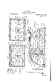
- Figure 1 is atransverse section on the line 00-0: of Fig. 2.
- Fig. 2 is a longitudinal sectional View
- Fig. 3 is a b'otto-ln view
- Fig. 4 is a cross section on the line 4-4 of Fig. 2
- Fig. 5 is a similar View on the line 5-5 of Fig. 2
- Fig. 6 is a horizontal section on the line G-6 of Fig. 2
- Fig. 7 is a detail section of-the journal connections for the drive wheels
- Fig. 8 is a de-v tail perspective of. the connections between the wheels and the crank shaft
- Fig. 1 is atransverse section on the line 00-0: of Fig. 2.
- Fig. 2 is a longitudinal sectional View
- Fig. 3 is a b'otto-ln view
- Fig. 4 is a cross section on the line 4-4 of Fig. 2
- Fig. 5 is a similar View on the line 5-5 of
- FIG. 9 is a front end View of the device showing the formation of the propeller yoke and the connections between the dust bag and the handle
- Fig.-l0 is a cross section on the V theret-hrough a portion of the wheels 30 for line 10--l0 of Fig. 4.
- a cleaner comprising a wheeled casing 10 including side walls 11 approximately semicircular in shape, and a curved top 12 thereover reaching to the lower edges of the sides at each end, as shown.
- An intake passage ing by means of a rigid bottom or floor let 11, and a detachable'partition 17 extending transversely ofthecasing and fitting snugly again'st the rear edges of the floors 14 and 16 and against suit-able battens 18 carried crating handle.
- This plate is suitably rounded and by extending the brass plate upwardly thereover and beneath the casing, any possibility of the edge of the plate becomingengaged with a carpet or other floor covering is obviated.
- This suction member engages frictionally with the carpet when the deviceis propelled, the wheels of the casing being disposed at the rear end thereof and carrying only a portion of its weight.
- the rear portion of the casing is open from the bottom, and the bottom edges of the sides 11 and the rear end of the top portion12 are provided with a floor portion 28 held by means of suitable screws engagedthrough the sides and top.
- the bottom 28 is provided with suitable lonpgitudinally extending slots 29 receiving engagement with a floor as will be subseits bottom end engaged slidably over the op-' there is a suction plate 25 comprising a blockcasing and having a brass plate 26 thereover,"
- a rabbet 27 in which there is detachably set 13 is formed at the forward end ofv the cas- Y stopping short'of the top 12 and the sides It will be I described,
- the lower" flagi3 of the partition 17 stops short of the lower 1 sur-- face of the floor portion 14 so, that the removable, bottom .28 may set snugly-there against-,
- the partition '17 is inserted slidably i the casing below, and. the engagement of thef bot tom thereoverzserves lllnpfcllb to hold it against disengagement.
- the shaft 39 is formed of a single bar of metal bent to present oppositely-disposed cranks 40. 1 A
- the wheels 30 are cast integrally and have 'hubs enlarged on their inner sides as shown at-41, and provided with a transverse groove 42 extending'diamet-ric'ally thereacross.
- The. block 48 is carried at the outer side of the head and is provided with a laterally projecting trunnion portion 49 engaged slidably in the adjacent'outer g'uide member 34.
- the guide block 49" is located ,upon the inner side of the head 47 and its outerface, and is provided with-a T-head 51 slidabl en aged in the adjacent guide. portion 33 o the race member 32.
- crank shaft it is only necessary to remove the screws 36 which allows the bearing blocks and the parts carried therein to be moved slidably out of the casing, after removal of the brace 32.
- the removal of the brace guide from between the heads 47 is largely facilitated because of the ivotal movement possible between the hen s and the side guides34 is being removed. This allows the brace guide to be loosened at its rear end and slid out without injuring the blocks.
- the T- heads on the inner blocks serve to holdthe bellows headsconstantly in a vertical plane, when the parts are in operative position.
- said member comprising a supporting block and a friction plate sccured outwardly thereof and having its forward edge portion turned upwardly and disposed between the block and the casing, slots being formed through the block and plate in registry with the first named slot, and suction means arranged to draw air and particles of matter through the slots.
- a machine of the class described-coin prising a casing, a bottom floor carried adjacent the forward end, a central floor carried "thereover, an intake opening being formed through the bottom 'fioor, an outlet opening being formed through the casing 1 above the second naihed floor, a removable partition extending transversely of the casing and resting against said floors, a re-' movable guide member engaged bet-ween the partition and-the rear end of the casin g guide members carried by the casing in spaced 're'lationwith the 'first named guide member, reciprocating suction devices ,carried upon the guide members and connected with said intake and outlet openings land means for operating the suction devices.
Landscapes
- Nozzles For Electric Vacuum Cleaners (AREA)
Description
v F. B.BUELL-. HAND OPERATED VACUUM CLEANER.
APPLICATION IILED SEP'I. 28 1909. 1,034,342. 4
3 SHEETS-SHEET l.
Patented Ju1y 30, 1912.
P. B. BUELL. .HAND 022mm) VACUUM CLEANER.
APPLIOATION FILED SEPT. 28. 1909. 1,034,342, Patented July 30, 1912.
UAW m Nq U wow now iron anew Y QM. NW W V In N? #09 WW 0? 0 M4- H nwmw 0 W F. B. BUELL. HAND OPERATED VACUUM CLEANER.
APPLICATION FILED SEPT. 28, 1909. v 4
- Patented July 30, 1-912.
3 sums-sum 3 (EM-@410; 55.5mm
v 4 g- M I I J/minus bnirnn STATES PATENT OFFICE.
:rnnn B. BUELL, or CANANDAIGUA, NEW YORK, Assrenon r0 JAMES- M. McCABE, or
- CANANDAIGUA, NEW YORK.
HAND-OPERATED VACUUM-CLEANER.
Specification of Letters Patent.
Patented July 30, 1912.
Application filed September 28, 1909. Serial No." 519,980.
To all whom it may concern:
Be it known that I, FRED B. BUELL, a citizen of the United States, residing at Canandaigua, in the county of Ontario and State of New York, have invented certain new and useful Improvements in Hand-Operated Vacuum-Cleaners, of which the following is a specification.
This invention relates to cleaning apparatus, and more particularly to a vacuum cleaneradapted to be operated by hand power.
A particular object is to provide a portable cleaner, comprising a wheeled casing adapted to be propelled acro-ss the floor by hand power, and carrying therein suitable mechanism for creating a vacuum and conducting accumulated dustand dirt to a"detachable receptacle carried by the casing.
A particular object of the invention is to provide operative mechanism, the parts of which are so designed as to be susceptible of manufacture at an extremely low. cost from stock material.
Another object is to provide a novel form of dust and dirt collector adapted to be readily detached from the machine, and replaced by a new one when desired.
Other objects and advantages will be apparent from' the following description, and it will be understoodthatchanges in the specific structure shown and described may be made within the scope of the claims, without departing from the spirit of the inven tion. 1 i
In the drawings forming a portion of this specification, and in which like numerals of reference indicate similar parts in the several views, Figure 1 is atransverse section on the line 00-0: of Fig. 2. Fig. 2 is a longitudinal sectional View, Fig. 3 is a b'otto-ln view, Fig. 4 is a cross section on the line 4-4 of Fig. 2, Fig. 5 is a similar View on the line 5-5 of Fig. 2, Fig. 6 is a horizontal section on the line G-6 of Fig. 2, Fig. 7 is a detail section of-the journal connections for the drive wheels, Fig. 8 is a de-v tail perspective of. the connections between the wheels and the crank shaft, Fig. 9 is a front end View of the device showing the formation of the propeller yoke and the connections between the dust bag and the handle, Fig.-l0 is a cross section on the V theret-hrough a portion of the wheels 30 for line 10--l0 of Fig. 4.
Referring to the drawings, there is shown a cleaner comprising a wheeled casing 10 including side walls 11 approximately semicircular in shape, and a curved top 12 thereover reaching to the lower edges of the sides at each end, as shown. An intake passage ing by means of a rigid bottom or floor let 11, and a detachable'partition 17 extending transversely ofthecasing and fitting snugly again'st the rear edges of the floors 14 and 16 and against suit-able battens 18 carried crating handle.
' Secured. to the bottom of the cylinder around the inlet 15, and outwardly thereof,
having' an elongated slot therethrough extending approximately the full width of the the forward edge of which is turned upwardly over the plate 25 and secured be tween the plate and the bottom of the easing. This plate is suitably rounded and by extending the brass plate upwardly thereover and beneath the casing, any possibility of the edge of the plate becomingengaged with a carpet or other floor covering is obviated. This suction member engages frictionally with the carpet when the deviceis propelled, the wheels of the casing being disposed at the rear end thereof and carrying only a portion of its weight. noted that as described, the rear portion of the casing is open from the bottom, and the bottom edges of the sides 11 and the rear end of the top portion12 are provided with a floor portion 28 held by means of suitable screws engagedthrough the sides and top. The bottom 28 is provided with suitable lonpgitudinally extending slots 29 receiving engagement with a floor as will be subseits bottom end engaged slidably over the op-' there is a suction plate 25 comprising a blockcasing and having a brass plate 26 thereover,"
a rabbet 27 in which there is detachably set 13 is formed at the forward end ofv the cas- Y stopping short'of the top 12 and the sides It will be I described, The lower" flagi3 of the partition 17 stops short of the lower 1 sur-- face of the floor portion 14 so, that the removable, bottom .28 may set snugly-there against-, The partition '17 is inserted slidably i the casing below, and. the engagement of thef bot tom thereoverzserves lllnpfcllb to hold it against disengagement.
Formed-centrally of the p' rtiti on there is a recess 31 receiving one end of a brace and guide member 32the oppositeend of-which is secured against the extreme rear portion .of the top 12,
"' approximately horizontally,
in-its opposite sides with longitudinally exand bears against the partition to'hold the partition snugly in position. It will be noted'that the member 32 extends and'is provided I tending grooves forming .guideways' 33. At-
v 7 tached to the inner 2o ing;slidably therethrough screw members 36 v carrying in threaded engagement on their inner ends suitable circular bearing blocks 37.
, Engaged revolubly in the blocks 37ithere are trunnion portions 38 of'a crank shaft 39,
carrying the wheels'BG, above mentioned.
The shaft 39 is formed of a single bar of metal bent to present oppositely-disposed cranks 40. 1 A
The wheels 30 are cast integrally and have 'hubs enlarged on their inner sides as shown at-41, and provided with a transverse groove 42 extending'diamet-ric'ally thereacross. The
wheels are engaged slidably upon the tram nion portions 38,-and agalnst the adjacent crank 40, so that one arm of the crank will jlie snugly in one side of the grove"42 to secured thereto are 19- respectively.
.hold' the wheel and crank, shaft securely against relative rotation, {The .wheels are provided with rubber tires Rectangular frames '45 having bellows .46
17 at opposite ends, ing the vertically adj acent pairs of openings Secured to the opposite end of the bellows there is a 'head plate 47, carrying' guide blocks 48- and: 49 respectively.
. The. block 48 is carried at the outer side of the head and is provided with a laterally projecting trunnion portion 49 engaged slidably in the adjacent'outer g'uide member 34. The guide block 49"is located ,upon the inner side of the head 47 and its outerface, and is provided with-a T-head 51 slidabl en aged in the adjacent guide. portion 33 o the race member 32. Secured centrally of the outer face of the head 47, there is an L-snaped bracket 52 formed of sheet metal and en-' gaged pivotally within the split end of a faces of the side portions secured to the partition each frame c1rcu1nscrib and similarthe outward'movement of dust and air to the dust collecting bag 23 as above described. By this means,'during the operation of the device, there will be 'a' constant passage of air inwardly through the intake and outwardly through the outlet 20 to the bag 23, whereby .the air will be strained from the dust and other particles by passing through the bag, leaving the dirt within the bag.
Centrally of the sides 11, there project outwardly headed bolts 61 pivotally engaged with which are the extremities of arms 58 of a yoke member having a central socket portion 59 disposed centrally over the casing and carrying a handle 60 therein. The arms 58 are formed of a single bar of metal, and are flattened at their extremities: In the manufacture of the device, its assemblage is greatly facilitated by the peculiar construction of the journals for the crank shaft, and the manner in which the repair is likewise greatly facilitated, as the removalof any part may be accomplished with a minimumexpenditure of time.'
It will be seen that to remove the crank shaft it is only necessary to remove the screws 36 which allows the bearing blocks and the parts carried therein to be moved slidably out of the casing, after removal of the brace 32.
Byforming the trunnions 49 on the outer guide blocks ofthe heads 47, and the T- head on the inner block, the removal of the brace guide from between the heads 47 is largely facilitated because of the ivotal movement possible between the hen s and the side guides34 is being removed. This allows the brace guide to be loosened at its rear end and slid out without injuring the blocks. The T- heads on the inner blocks serve to holdthe bellows headsconstantly in a vertical plane, when the parts are in operative position.
- What is claimed is:
when the central guide 32 1. In' a: device of the class described, a
over saidslot, said member comprising a supporting block and a friction plate sccured outwardly thereof and having its forward edge portion turned upwardly and disposed between the block and the casing, slots being formed through the block and plate in registry with the first named slot, and suction means arranged to draw air and particles of matter through the slots.
2. A machine of the class described-coinprising a casing, a bottom floor carried adjacent the forward end, a central floor carried "thereover, an intake opening being formed through the bottom 'fioor, an outlet opening being formed through the casing 1 above the second naihed floor, a removable partition extending transversely of the casing and resting against said floors, a re-' movable guide member engaged bet-ween the partition and-the rear end of the casin g guide members carried by the casing in spaced 're'lationwith the 'first named guide member, reciprocating suction devices ,carried upon the guide members and connected with said intake and outlet openings land means for operating the suction devices.
In test-imony'whereo'f I affix my signa= 25 Copies of this patent may be obtained for five cents each, by addressing the Commissioner of Patents,
Washington, D. c."
Priority Applications (1)
| Application Number | Priority Date | Filing Date | Title |
|---|---|---|---|
| US51998009A US1034342A (en) | 1909-09-28 | 1909-09-28 | Hand-operated vacuum-cleaner. |
Applications Claiming Priority (1)
| Application Number | Priority Date | Filing Date | Title |
|---|---|---|---|
| US51998009A US1034342A (en) | 1909-09-28 | 1909-09-28 | Hand-operated vacuum-cleaner. |
Publications (1)
| Publication Number | Publication Date |
|---|---|
| US1034342A true US1034342A (en) | 1912-07-30 |
Family
ID=3102623
Family Applications (1)
| Application Number | Title | Priority Date | Filing Date |
|---|---|---|---|
| US51998009A Expired - Lifetime US1034342A (en) | 1909-09-28 | 1909-09-28 | Hand-operated vacuum-cleaner. |
Country Status (1)
| Country | Link |
|---|---|
| US (1) | US1034342A (en) |
Cited By (1)
| Publication number | Priority date | Publication date | Assignee | Title |
|---|---|---|---|---|
| KR20210009808A (en) * | 2019-07-18 | 2021-01-27 | 박철순 | Vacuum cleaner without power source |
-
1909
- 1909-09-28 US US51998009A patent/US1034342A/en not_active Expired - Lifetime
Cited By (1)
| Publication number | Priority date | Publication date | Assignee | Title |
|---|---|---|---|---|
| KR20210009808A (en) * | 2019-07-18 | 2021-01-27 | 박철순 | Vacuum cleaner without power source |
Similar Documents
| Publication | Publication Date | Title |
|---|---|---|
| US500415A (en) | Lewis p | |
| US11344171B2 (en) | Floor surface cleaning machine and cleaning method using the same | |
| US2683276A (en) | Cleaning head for suction type carpet sweepers | |
| KR19980023805A (en) | Brush Drive for Vacuum Cleaner | |
| US1033016A (en) | Vacuum cleaning-tool. | |
| US1773961A (en) | Vacuum sweeper | |
| US2202999A (en) | Suction cleaner | |
| US862053A (en) | Carpet-beating machine. | |
| US1037027A (en) | Vacuum-cleaner. | |
| US1795533A (en) | Vacuum-cleaning-machine attachment | |
| US1940954A (en) | Suction cleaner | |
| US1294473A (en) | Vacuum-cleaner. | |
| US2246111A (en) | Scrubbing machine for floors and floor coverings | |
| US628505A (en) | Pneumatic carpet-sweeper. | |
| US1035460A (en) | Vacuum carpet-cleaner. | |
| US946801A (en) | Vacuum-cleaner. | |
| US1682013A (en) | Sanding machine | |
| US1818872A (en) | Vacuum cleaner | |
| US1239581A (en) | Cleaning device. | |
| USRE16763E (en) | hoover | |
| US1303819A (en) | Victor j | |
| US949370A (en) | Pneumatic cleaner. | |
| US112837A (en) | Improvement in sweeping-machines | |
| US328057A (en) | Street-sweeper | |
| US573554A (en) | stump |