US103303A - Improvement in machines for beveling and crozing barrels - Google Patents
Improvement in machines for beveling and crozing barrels Download PDFInfo
- Publication number
- US103303A US103303A US103303DA US103303A US 103303 A US103303 A US 103303A US 103303D A US103303D A US 103303DA US 103303 A US103303 A US 103303A
- Authority
- US
- United States
- Prior art keywords
- beveling
- machines
- improvement
- crozing
- barrels
- Prior art date
- Legal status (The legal status is an assumption and is not a legal conclusion. Google has not performed a legal analysis and makes no representation as to the accuracy of the status listed.)
- Expired - Lifetime
Links
- XLYOFNOQVPJJNP-UHFFFAOYSA-N water Substances O XLYOFNOQVPJJNP-UHFFFAOYSA-N 0.000 description 3
- 241000018850 Setina Species 0.000 description 1
- 238000009499 grossing Methods 0.000 description 1
- 230000000284 resting effect Effects 0.000 description 1
Images
Classifications
-
- B—PERFORMING OPERATIONS; TRANSPORTING
- B27—WORKING OR PRESERVING WOOD OR SIMILAR MATERIAL; NAILING OR STAPLING MACHINES IN GENERAL
- B27H—BENDING WOOD OR SIMILAR MATERIAL; COOPERAGE; MAKING WHEELS FROM WOOD OR SIMILAR MATERIAL
- B27H5/00—Manufacture of tubes, coops, or barrels
- B27H5/08—Finishing barrels, e.g. cutting grooves
- B27H5/10—Trussing or hooping barrels
Definitions
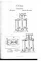
- VrvrncHINEs non BEVELING AND cnoznve BARRBLS.
- the base A In the centerof the base A is a cylinder, a, in which plays a plunger, b, attached to the under side of a cross-head, D, which has arms, d d, with wings, e e, on
- the pumps are set on a reservoir, h, from which they take water.
- An outlet-pipe, l has a cock, m, allowing the water to return to the reservoir.
- the pump-rods are worked by a crank-shaft, k, set in arms on the top of frame O, the said shaft k being driven bythe pulley t.
- the sliding tool-holders 4a av n Fitted into grooves in the upper side of the disk M are the sliding tool-holders 4a av n, on the ends of which are secured, to one a cutter for smoothing the inside of the chine; to another a, cutter for beveling the edge of the chine, and to the third a cutter for cutting the croze inthe chine of a'barrel.
- the inner ends of the tool-holders have a rack o them, as seen at fn in g. 3.
- the disk M Within the hub of' the disk M are placed ratchet-. wheels, o, meshing with the racks on the tool-holders.
- the rod p is connected at the top by a ball-jont tc a lever, t, pivoted at S.
- the other end ofthe lever t is connected to an elevating-screw, fv, having a crank-wheel and handle, w, by which it may be turned.
- An adjustable screw is set ina projection, u, on the frame G for determining the depth to which the lever shall fall.
- a barrel having the truss-hoops upon it is set into the ring E, the hoop resting on its edge, when the pumps are set in motion, and, by the hydraulic, force the barrel is trussed.
- the disk being in motion, by turning down the level' t, by the screw fv, the rod p carries the tool-holders outward, and the chine of the barrel is worked on.
- the rod 11 is again carried up, withdrawing the tools, the cock V'mis opened, when the water ows back into the reservoir h, and the ring E and cross-head D are lowered.
- the barrel may be taken out Yand set in the ring E, the other end up, when the operation is repeated, working oli' the other end in like manner to the first.
Landscapes
- Engineering & Computer Science (AREA)
- Life Sciences & Earth Sciences (AREA)
- Manufacturing & Machinery (AREA)
- Mechanical Engineering (AREA)
- Wood Science & Technology (AREA)
- Forests & Forestry (AREA)
- Crystals, And After-Treatments Of Crystals (AREA)
Description
naar ,eine
@at-wt) We.
Letters Patent No; 103,303, aan May 24, 1870.
' IMPROVEMENT 1N VrvrncHINEs non BEVELING AND cnoznve BARRBLS.
The Schedule referred tn in these'Lettexs Patent and making part of the same y v LHARYA. CRossLEY, of C1cveland,in the county l of Cuyahoga and State of Ohio, have'invented certain l Improvements in Barrel-trussing, Beveling or Chamfering and Orozing-Machines, of which the following is a specication.
able number' of standards, B B, to the top of which is secured a'stron'g circular frame, C. These, together,
make the'frame work, which carries and supports the working-parts.
In the centerof the base A is a cylinder, a, in which plays a plunger, b, attached to the under side of a cross-head, D, which has arms, d d, with wings, e e, on
each end, embracing the standards B B, upon which the cross-head is made to slide.L
Upon the arms d d issecured a ring, E.
Just'outside of theframe are placed force-pumps, F F, connected with the cylinder @by a pipe, g. i
The pumps are set on a reservoir, h, from which they take water.
An outlet-pipe, l, has a cock, m, allowing the water to return to the reservoir.
The pump-rods are worked by a crank-shaft, k, set in arms on the top of frame O, the said shaft k being driven bythe pulley t. I
On the top of the circular frame C is-placcd aframe, G, in which is arranged an upright hollow shaft, H,
having its bearings on the said frame Gr, and which is` driven by thevpulley I.
On the lower-,end of the shaft H is a disk, M, which turnsj ust within the circular frame'O. l
' Fitted into grooves in the upper side of the disk M are the sliding tool-holders 4a av n, on the ends of which are secured, to one a cutter for smoothing the inside of the chine; to another a, cutter for beveling the edge of the chine, and to the third a cutter for cutting the croze inthe chine of a'barrel. Y
The inner ends of the tool-holders have a rack o them, as seen at fn in g. 3.
Within the hub of' the disk M are placed ratchet-. wheels, o, meshing with the racks on the tool-holders.
thread-vent on its lower end, which meshes with the ratchetwheels o.
The rod p is connected at the top by a ball-jont tc a lever, t, pivoted at S.
` The other end ofthe lever t is connected to an elevating-screw, fv, having a crank-wheel and handle, w, by which it may be turned.
An adjustable screw is set ina projection, u, on the frame G for determining the depth to which the lever shall fall. By this arrangement the tool-holders are carried in and out; v
The operation of this machine is as follows:
A barrel having the truss-hoops upon it is set into the ring E, the hoop resting on its edge, when the pumps are set in motion, and, by the hydraulic, force the barrel is trussed. At the same time, the disk being in motion, by turning down the level' t, by the screw fv, the rod p carries the tool-holders outward, and the chine of the barrel is worked on. The rod 11 is again carried up, withdrawing the tools, the cock V'mis opened, when the water ows back into the reservoir h, and the ring E and cross-head D are lowered. The barrel may be taken out Yand set in the ring E, the other end up, when the operation is repeated, working oli' the other end in like manner to the first.
. 1. The arrangement of the frame G, ring C, shaft H, rack 11, lever t, screw a c, the' regulating-screw, pinious 0,. disk M, and cutters n, upon the columns B B, and platform A, all constructed, arranged, and operating substantially as described.
2. In combination with the above, the cylinder a, piston b, frameD d c, ring E, pumps F, and a reservoir, connecting-pipes and pump-operating mechanism, all substantially as herein described.4
HARRY A. OROSSLEY.
Witnesses Gao. W. Tlnrtrs. no. BESTER.
XVithin the hollow shaft H is a rod, p, having a,
Publications (1)
| Publication Number | Publication Date |
|---|---|
| US103303A true US103303A (en) | 1870-05-24 |
Family
ID=2172789
Family Applications (1)
| Application Number | Title | Priority Date | Filing Date |
|---|---|---|---|
| US103303D Expired - Lifetime US103303A (en) | Improvement in machines for beveling and crozing barrels |
Country Status (1)
| Country | Link |
|---|---|
| US (1) | US103303A (en) |
-
0
- US US103303D patent/US103303A/en not_active Expired - Lifetime
Similar Documents
| Publication | Publication Date | Title |
|---|---|---|
| US1852387A (en) | Woodworking machine | |
| US103303A (en) | Improvement in machines for beveling and crozing barrels | |
| CN207415133U (en) | Process elliptical fixture outside wooden barrel | |
| CN109015938A (en) | A kind of efficient board cutting machine | |
| US90550A (en) | Improvement in cask-washing- machines | |
| US4966A (en) | Barbel machinery | |
| US150829A (en) | Improvement in machines for cleaning cog-wheels | |
| DE35218C (en) | Fafs cleaning and swiveling machine for simultaneous cleaning of the transport barrels from the outside and inside | |
| US102920A (en) | Improvement in machine for the manufacture of wooden trays | |
| US80382A (en) | H-bnbt barber | |
| US128786A (en) | Improvement in machines for making barrels | |
| US532A (en) | Machine for reducing and cutting dye woods and bark | |
| US80338A (en) | daniels | |
| USRE2518E (en) | Improved machine foe sxoueing leathee | |
| US1802798A (en) | Grinding machine | |
| US145942A (en) | Improvement in machines for forcing hoops on barrels | |
| US250181A (en) | Machine | |
| US82600A (en) | Improvement in turning wagon-hubs | |
| US141091A (en) | Improvement in broaching-machines | |
| US123048A (en) | Improvement in shingle-machines | |
| DE63305C (en) | Apparatus for tanning | |
| US100387A (en) | Improvement in machines for dressing leather | |
| US81939A (en) | Thomas payne | |
| US578448A (en) | frueinsholz | |
| US572207A (en) | Gear-cutting machine |