US10329962B2 - Internal combustion engine system - Google Patents
Internal combustion engine system Download PDFInfo
- Publication number
- US10329962B2 US10329962B2 US15/877,437 US201815877437A US10329962B2 US 10329962 B2 US10329962 B2 US 10329962B2 US 201815877437 A US201815877437 A US 201815877437A US 10329962 B2 US10329962 B2 US 10329962B2
- Authority
- US
- United States
- Prior art keywords
- cam
- cylinder
- pins
- crank angle
- drive
- Prior art date
- Legal status (The legal status is an assumption and is not a legal conclusion. Google has not performed a legal analysis and makes no representation as to the accuracy of the status listed.)
- Expired - Fee Related
Links
Images


Classifications
-
- F—MECHANICAL ENGINEERING; LIGHTING; HEATING; WEAPONS; BLASTING
- F01—MACHINES OR ENGINES IN GENERAL; ENGINE PLANTS IN GENERAL; STEAM ENGINES
- F01L—CYCLICALLY OPERATING VALVES FOR MACHINES OR ENGINES
- F01L1/00—Valve-gear or valve arrangements, e.g. lift-valve gear
- F01L1/02—Valve drive
- F01L1/04—Valve drive by means of cams, camshafts, cam discs, eccentrics or the like
- F01L1/047—Camshafts
-
- F—MECHANICAL ENGINEERING; LIGHTING; HEATING; WEAPONS; BLASTING
- F01—MACHINES OR ENGINES IN GENERAL; ENGINE PLANTS IN GENERAL; STEAM ENGINES
- F01L—CYCLICALLY OPERATING VALVES FOR MACHINES OR ENGINES
- F01L1/00—Valve-gear or valve arrangements, e.g. lift-valve gear
- F01L1/02—Valve drive
- F01L1/04—Valve drive by means of cams, camshafts, cam discs, eccentrics or the like
- F01L1/08—Shape of cams
-
- F—MECHANICAL ENGINEERING; LIGHTING; HEATING; WEAPONS; BLASTING
- F01—MACHINES OR ENGINES IN GENERAL; ENGINE PLANTS IN GENERAL; STEAM ENGINES
- F01L—CYCLICALLY OPERATING VALVES FOR MACHINES OR ENGINES
- F01L13/00—Modifications of valve-gear to facilitate reversing, braking, starting, changing compression ratio, or other specific operations
- F01L13/0015—Modifications of valve-gear to facilitate reversing, braking, starting, changing compression ratio, or other specific operations for optimising engine performances by modifying valve lift according to various working parameters, e.g. rotational speed, load, torque
- F01L13/0036—Modifications of valve-gear to facilitate reversing, braking, starting, changing compression ratio, or other specific operations for optimising engine performances by modifying valve lift according to various working parameters, e.g. rotational speed, load, torque the valves being driven by two or more cams with different shape, size or timing or a single cam profiled in axial and radial direction
-
- F—MECHANICAL ENGINEERING; LIGHTING; HEATING; WEAPONS; BLASTING
- F02—COMBUSTION ENGINES; HOT-GAS OR COMBUSTION-PRODUCT ENGINE PLANTS
- F02D—CONTROLLING COMBUSTION ENGINES
- F02D41/00—Electrical control of supply of combustible mixture or its constituents
-
- F—MECHANICAL ENGINEERING; LIGHTING; HEATING; WEAPONS; BLASTING
- F02—COMBUSTION ENGINES; HOT-GAS OR COMBUSTION-PRODUCT ENGINE PLANTS
- F02D—CONTROLLING COMBUSTION ENGINES
- F02D41/00—Electrical control of supply of combustible mixture or its constituents
- F02D41/0002—Controlling intake air
-
- F—MECHANICAL ENGINEERING; LIGHTING; HEATING; WEAPONS; BLASTING
- F01—MACHINES OR ENGINES IN GENERAL; ENGINE PLANTS IN GENERAL; STEAM ENGINES
- F01L—CYCLICALLY OPERATING VALVES FOR MACHINES OR ENGINES
- F01L13/00—Modifications of valve-gear to facilitate reversing, braking, starting, changing compression ratio, or other specific operations
- F01L13/0015—Modifications of valve-gear to facilitate reversing, braking, starting, changing compression ratio, or other specific operations for optimising engine performances by modifying valve lift according to various working parameters, e.g. rotational speed, load, torque
- F01L13/0036—Modifications of valve-gear to facilitate reversing, braking, starting, changing compression ratio, or other specific operations for optimising engine performances by modifying valve lift according to various working parameters, e.g. rotational speed, load, torque the valves being driven by two or more cams with different shape, size or timing or a single cam profiled in axial and radial direction
- F01L2013/0052—Modifications of valve-gear to facilitate reversing, braking, starting, changing compression ratio, or other specific operations for optimising engine performances by modifying valve lift according to various working parameters, e.g. rotational speed, load, torque the valves being driven by two or more cams with different shape, size or timing or a single cam profiled in axial and radial direction with cams provided on an axially slidable sleeve
-
- F—MECHANICAL ENGINEERING; LIGHTING; HEATING; WEAPONS; BLASTING
- F01—MACHINES OR ENGINES IN GENERAL; ENGINE PLANTS IN GENERAL; STEAM ENGINES
- F01L—CYCLICALLY OPERATING VALVES FOR MACHINES OR ENGINES
- F01L2800/00—Methods of operation using a variable valve timing mechanism
- F01L2800/01—Starting
-
- F—MECHANICAL ENGINEERING; LIGHTING; HEATING; WEAPONS; BLASTING
- F01—MACHINES OR ENGINES IN GENERAL; ENGINE PLANTS IN GENERAL; STEAM ENGINES
- F01L—CYCLICALLY OPERATING VALVES FOR MACHINES OR ENGINES
- F01L2820/00—Details on specific features characterising valve gear arrangements
- F01L2820/04—Sensors
- F01L2820/041—Camshafts position or phase sensors
-
- F—MECHANICAL ENGINEERING; LIGHTING; HEATING; WEAPONS; BLASTING
- F01—MACHINES OR ENGINES IN GENERAL; ENGINE PLANTS IN GENERAL; STEAM ENGINES
- F01L—CYCLICALLY OPERATING VALVES FOR MACHINES OR ENGINES
- F01L2820/00—Details on specific features characterising valve gear arrangements
- F01L2820/04—Sensors
- F01L2820/042—Crankshafts position
-
- F—MECHANICAL ENGINEERING; LIGHTING; HEATING; WEAPONS; BLASTING
- F02—COMBUSTION ENGINES; HOT-GAS OR COMBUSTION-PRODUCT ENGINE PLANTS
- F02D—CONTROLLING COMBUSTION ENGINES
- F02D41/00—Electrical control of supply of combustible mixture or its constituents
- F02D41/0002—Controlling intake air
- F02D2041/001—Controlling intake air for engines with variable valve actuation
-
- F—MECHANICAL ENGINEERING; LIGHTING; HEATING; WEAPONS; BLASTING
- F02—COMBUSTION ENGINES; HOT-GAS OR COMBUSTION-PRODUCT ENGINE PLANTS
- F02D—CONTROLLING COMBUSTION ENGINES
- F02D41/00—Electrical control of supply of combustible mixture or its constituents
- F02D41/009—Electrical control of supply of combustible mixture or its constituents using means for generating position or synchronisation signals
- F02D2041/0092—Synchronisation of the cylinders at engine start
-
- F—MECHANICAL ENGINEERING; LIGHTING; HEATING; WEAPONS; BLASTING
- F02—COMBUSTION ENGINES; HOT-GAS OR COMBUSTION-PRODUCT ENGINE PLANTS
- F02D—CONTROLLING COMBUSTION ENGINES
- F02D41/00—Electrical control of supply of combustible mixture or its constituents
- F02D41/02—Circuit arrangements for generating control signals
- F02D41/04—Introducing corrections for particular operating conditions
- F02D41/06—Introducing corrections for particular operating conditions for engine starting or warming up
- F02D41/062—Introducing corrections for particular operating conditions for engine starting or warming up for starting
-
- F—MECHANICAL ENGINEERING; LIGHTING; HEATING; WEAPONS; BLASTING
- F16—ENGINEERING ELEMENTS AND UNITS; GENERAL MEASURES FOR PRODUCING AND MAINTAINING EFFECTIVE FUNCTIONING OF MACHINES OR INSTALLATIONS; THERMAL INSULATION IN GENERAL
- F16H—GEARING
- F16H53/00—Cams or cam-followers, e.g. rollers for gearing mechanisms
- F16H53/02—Single-track cams for single-revolution cycles; Camshafts with such cams
- F16H53/025—Single-track cams for single-revolution cycles; Camshafts with such cams characterised by their construction, e.g. assembling or manufacturing features
-
- Y—GENERAL TAGGING OF NEW TECHNOLOGICAL DEVELOPMENTS; GENERAL TAGGING OF CROSS-SECTIONAL TECHNOLOGIES SPANNING OVER SEVERAL SECTIONS OF THE IPC; TECHNICAL SUBJECTS COVERED BY FORMER USPC CROSS-REFERENCE ART COLLECTIONS [XRACs] AND DIGESTS
- Y02—TECHNOLOGIES OR APPLICATIONS FOR MITIGATION OR ADAPTATION AGAINST CLIMATE CHANGE
- Y02T—CLIMATE CHANGE MITIGATION TECHNOLOGIES RELATED TO TRANSPORTATION
- Y02T10/00—Road transport of goods or passengers
- Y02T10/10—Internal combustion engine [ICE] based vehicles
- Y02T10/40—Engine management systems
Definitions
- the present disclosure relates to an internal combustion engine system.
- JP 2009-228543 A discloses a variable valve device for a multi-cylinder engine in which two types of intake cams having different lift amounts (specifically, large lift cams and small lift cams) are used for driving an intake valve of each cylinder.
- the two types of intake cams are carried by cam carriers.
- the cam carriers are slidably provided in an axial direction of a cam shaft. When the cam carriers slide in the axial direction of the cam shaft, the intake cams are switched therebetween to change the lift amount of the intake valve.
- the cam carriers are also provided for each cylinder group and slide in order of the cylinder group. In other word, in the valve device, a switch of the intake cams is performed in order of units of the cam carriers.
- JP 2010-168966 A discloses an engine start control with a valve device in which one type of intake cam is continuously changeable in a lift amount and an operation angle. This start control is performed for increasing the lift amount of the intake valve to a predetermined value or more when the engine is restarted after automatic stop of the engine. JP 2010-168966 A also discloses an example of the start control for driving the valve device in which the lift amount of the intake cam is maximum immediately before the automatic stop of the engine.
- JP 2013-148012 A discloses a cylinder discrimination method at an engine start of a four-stroke typed engine.
- compression top dead center TDC of each cylinder is specified based on signals from a crank angle sensor and a cam angle sensor while a starter is driven to rotate a crank shaft and a cam shaft during the engine start.
- the crank shaft and the cam shaft are provided with a rotor (specifically, a crank rotor and a cam rotor). Since the rotor includes chipped tooth parts and positions of the chipped tooth parts are known beforehand. Therefore, the compression top dead center of each cylinder is specified by obtaining the signals on the chipped tooth parts.
- the cam profiles of all the intake cams of all the cylinders become a suitable cam profile for starting the engine (hereinafter, also referred to as a “starting cam profile”) when the engine is started.
- starting cam profile a suitable cam profile for starting the engine
- the start control of JP 2010-168966 A enables the cam profiles of all the intake cams to be switched to the starting cam profile before the engine is started. However, the switching to the starting cam profile is not necessarily successful. If the switching fails, the combustion in a cylinder corresponding to the intake cam which failed in the switching is not appropriately performed, and the engine start-up performance may be reduced.
- the present disclosure addresses the above problem, and an object of the present disclosure is to suppress the start delay of the engine due to the switching to the starting cam profile in the multi-cylinder engine in which cam profiles are switched in order of units of the cam carriers.
- the present disclosure provides an internal combustion engine system comprising an internal combustion engine comprising multiple cylinder, multiple types of cams, cam carriers, multiple switching mechanisms, and a control device.
- the multiple types of cams have different cam profiles per cylinder.
- the multiple types of cams are configured to drive intake valves which are provided in each cylinder.
- the cam carriers are provided on a cam shaft which rotates synchronously with a crank shaft of the internal combustion engine.
- Each of the cam carriers supports the multiple types of cams per cylinder or cylinder groups.
- the spiral-shaped groove comprises an inclined part which inclines with respect to the cam shaft and a front orthogonal part which is orthogonal to the cam shaft and communicates with the inclined part on a front side in the rotation direction of the cam shaft, and a rear orthogonal part which is orthogonal to the cam shaft and communicates with the inclined part on a rear side in the rotation direction of the cam shaft.
- the switching mechanisms are provided corresponding to the cam carriers.
- the switching mechanisms are configured to slide the cam carriers sequentially in the axial direction of the cam shaft in accordance with ejection operations of pins which are configured to engage with the spiral-shaped groove.
- the switching mechanisms are also configured to switch drive cams that actually drive the intake valves among the multiple types of the cams.
- the control device is configured to operate the switching mechanisms.
- the control device is also configured to, when operating the switching mechanisms during non-engine start, execute a cylinder discrimination based on information about rotation positions of the crank shaft and the cam shaft and determine start timing of ejection operations of the pins based on the result of the cylinder discrimination.
- the control device is also configured to, when operating the switching mechanisms during engine start, start to perform the ejection operations of the pins so that at least one of the pins is ejected from at least one of the switching mechanisms before the execution of the cylinder discrimination.
- the control device may be configured to, when operating the switching mechanisms during the engine start, permit combustion in all cylinders or cylinder groups when a retraction operation of at least one of the pins which is ejected from at least one of the switching mechanisms is completed.
- the internal combustion engine system may comprise a motor which is configured to rotate the crank shaft during the engine start.
- the control device may be configured to, when operating the switching mechanisms during the engine start, start the ejection operations of the pins in all the switching mechanisms before the execution of the cylinder discrimination and drive the motor after the ejected pins from all of the switching mechanisms are seated on the cam carriers.
- the control device may be configured to start the ejection operations of the pins in all the switching mechanisms at the same timing.
- the motor When the motor is driven after the ejected pins from all of the switching mechanisms are seated on the cam carriers, the motor starts to rotate after the ejected pins are seated on the cam carriers. Therefore, the ejected pins are able to engage with the spiral-shaped grooves with high probability. Further, when the ejection operations of the pins in all the switching mechanisms is started at the same timing, the ejected pins are able to seat on the cam carriers at substantially the same timing. Therefore, the ejected pins are able to engage with the spiral-shaped grooves with high probability.
- the control device may be configured to, when operating the switching mechanisms during the engine start, sequentially start the ejection operations of the pins for each mechanism group obtained by dividing the switching mechanisms into at least two mechanism groups.
- the control device may also be configured to permit combustion in all cylinders or cylinder groups when the retraction operation of at least one of the pins is completed which was ejected from a switching mechanism belonging to a mechanism group whose order of the ejection operation is the last of the mechanism groups.
- the control device may also be configured to start the ejection operations of the pins belonging to a second mechanism group after the ejection operations of the pins belonging to a first mechanism group are completed.
- the switching of the drive cams can be executed by sequentially starting the ejection operations of the pins for each mechanism groups.
- the ejection operations of the pins are sequentially started for each mechanism groups, when combustion in all cylinders or cylinder groups are permitted when the retraction operation of at least one of the pins is completed which was ejected from a switching mechanism belonging to a mechanism group whose order of the ejection operation is the last of the mechanism groups, it is possible to suppress the delay in first combustion timing of the internal combustion engine.
- the switching of the drive cams can be executed by starting the ejection operations of the pins belonging to the second mechanism group after the ejection operations of the pins belonging to the first mechanism group are completed.
- FIG. 1 is a schematic diagram for describing a configuration example of a system according to a first embodiment of the present disclosure
- FIGS. 2A to 2D each are a diagram for describing an example of a rotational operation of a cam carrier 12 by an engagement between a pin 20 and a groove 18 shown in FIG. 1 ;
- FIG. 3 is a diagram for describing an example of a relationship between a switch operation of a drive cam and four strokes of an engine
- FIG. 4 is a diagram for describing an example of the switch operation of the drive cam in a normal state of an engine according to the first embodiment of the present disclosure
- FIGS. 5 and 6 each are a diagram for describing an example of a processing routine relevant to a start control executed by an ECU in the first embodiment of the present disclosure
- FIG. 7 is a diagram for describing an example of the switch operation of the drive cam during an engine start according to the first embodiment of the present disclosure
- FIG. 8 is a diagram for describing a problem in a case where it is assumed that the switch operation in the normal state of the engine described with reference to FIG. 4 is performed during the engine start;
- FIG. 9 is a diagram for describing another example of the switch operation of the drive cam during the engine start according to the first embodiment of the present disclosure.
- FIG. 10 is a diagram for describing an example of a processing routine relevant to the start control executed by the ECU in a second embodiment of the present disclosure
- FIGS. 11 and 12 each are a diagram for describing an example of a processing routine relevant to the start control executed by the ECU in a third embodiment of the present disclosure
- FIG. 13 is a diagram for describing an example of the switch operation of the drive cam during the engine start according to the third embodiment of the present disclosure
- FIG. 14 is a diagram for describing a cam carrier including three types of intake cams and a configuration of a solenoid actuator to be combined with the cam carrier;
- FIG. 15 is a diagram for describing an example of a switch operation of the drive cam during the engine start on the premise of the cam carrier shown in FIG. 14 .
- FIGS. 1 to 9 a first embodiment of the present disclosure will be described with reference to FIGS. 1 to 9 .
- FIG. 1 is a schematic diagram for describing a configuration example of a system according to the first embodiment of the present disclosure.
- the system shown in FIG. 1 is an internal combustion engine system which is mounted on a vehicle.
- the internal combustion engine is a four-stroke type reciprocating engine and it is also a straight four-cylinder type engine.
- An ignition order of the engine is a first cylinder (#1 cylinder), a third cylinder (#3 cylinder), a fourth cylinder (#4 cylinder), and a second cylinder (#2 cylinder).
- the number of cylinders of the engine may be two, three, or five or more.
- the ignition order of the engine is not particularly limited.
- a valve system shown in FIG. 1 includes a cam shaft 10 .
- the cam shaft 10 is connected with a crankshaft (not shown), and is rotated in synchronism with the crankshaft.
- Four cam carriers 12 are arranged at intervals on the cam shaft 10 , each of the cam carriers having a hollow shaft formed therein.
- the cam carriers 12 are slidably arranged in an axial direction of the cam shaft 10 while being fixed in a rotational direction of the cam shaft 10 .
- the cam carrier 12 includes two types of intake cams 14 and 16 that have different cam profiles profile means at least one of a lift amount and an operation angle, the same shall apply hereinafter), the intake cams 14 and 16 being provided adjacently to each other.
- the intake cam 14 has an operation angle and a lift amount that are smaller than those of the intake cam 16 , for example.
- the intake cam 14 and the intake cam 16 are also called as a “small cam 14 ” and a “large cam 16 ”, respectively, for the convenience of description.
- Two pairs of small and large cams 14 and 16 are provided for each cylinder. This is because two intake valves are disposed for each cylinder. In the present disclosure, however, the number of intake valves per cylinder may be one, or three or more.
- a surface of the cam carrier 12 has a groove 18 formed thereon and spirally extending while rotating in the axial direction of the cam shaft 10 .
- the grooves 18 respectively provided on the cam carriers are formed with a phase difference among the cylinders. Specifically, the phase difference of 90° is provided between the groove 18 for #1 cylinder and the groove 18 for #3 cylinder, between the groove 18 for #3 cylinder and the groove 18 for #4 cylinder, between the groove 18 for #4 cylinder and the groove 18 for #2, and between the groove 18 #2 cylinder and the groove 18 for #1 cylinder.
- the two of the branches of the groove 18 for each cylinder join one in the middle.
- groove 18 a a part after joining
- grooves 18 b and 18 c a part before joining
- the depth of the groove 18 a is constant in the middle portion.
- the depth of the groove 18 a is not constant from the middle portion to the end portion. From the middle portion to the end portion, the depth of the groove 18 a is formed so as to become shallower toward the end portion.
- the valve system shown in FIG. 1 includes a solenoid actuator 24 having two pins 20 and 22 and a coil for each cylinder.
- the pins 20 and 22 are composed of magnetic body.
- the pin 20 or the pin 22
- the ejected pin 20 is seated on the groove 18 b (or the groove 18 c ) and the ejected pin 20 (or the ejected pin 22 ) engages with the groove 18 .
- FIGS. 2A to 2D each are a diagram for describing an example of a rotational operation of the cam carrier 12 by engagement between the pin 20 and the groove 18 .
- FIGS. 2A to 2D assume that the cam carrier 12 is rotated from an upper side to a lower side.
- FIGS. 2A to 2D each illustrate only the cam carrier 12 and the solenoid actuator 24 , and rocker arm rollers 30 that come into contact with the small cam 14 and the large cam 16 .
- both of the pins 20 and 22 are retracted into the solenoid actuator 24 .
- the pin 20 is positioned to face the groove 18 b
- the pin 22 is positioned to face a part of the cam carrier 12 here the groove 18 is not formed.
- FIG. 2B illustrates a posture of the cam carrier 12 that is rotated by 90° from a state shown in FIG. 2A .
- the groove 18 a moved to a back side of the cam carrier 12
- the grooves 18 b and 18 c are moved to a front side of the cam carrier 12 .
- the grooves 18 b and 18 c shown in FIG. 2B are orthogonal to the shaft of the cam carrier 12 .
- the pin 20 is ejected from the solenoid actuator 24 and is seated on the groove 18 b .
- An ejection operations of the pins 20 is started so that the pin 20 seats on a part where the groove 18 b is orthogonal to the axis of the cam carrier 12 (hereinafter also referred to as an “orthogonal part”).
- the pin 20 ejected from the solenoid actuator 24 is smoothly inserted into the orthogonal part of the groove 18 b and engaged with the groove 18 b.
- FIG. 2C illustrates a posture of the cam carrier 12 that is rotated by 90° from a state shown in FIG. 2B .
- FIG. 2C and FIG. 2B when the cam carrier 12 is rotated, the whole area of the groove 18 a is completely moved to the back side of the cam carrier 12 , whereas the grooves 18 b and 18 c are further moved to the front side of the cam carrier 12 .
- the cam carrier 12 is slid in a left direction.
- FIG. 2D illustrates a posture of the cam carrier 12 that is rotated by 90° from a state shown in FIG. 2C .
- the cam carrier 12 when the cam carrier 12 is rotated, the inclined parts of the grooves 18 b and 18 c are moved to the back side of the cam carrier 12 .
- the pin 20 engages with the groove 18 a .
- the pin 20 in the engagement state with the groove 18 a moves with the rotation of the cam carrier 12 to the shallow end portion of the groove 18 a .
- the pin 20 moves to the shallow end portion of the groove 18 a , the pin 20 is pushed from the shallow end portion and goes back to the solenoid actuator 24 side.
- a cam with which the rocker arm roller 26 comes into contact (hereinafter also referred to as a “drive cam”) is switched from the small cam 14 to the large cam 16 .
- a switch operation from the large cam 16 to the small 14 is performed as follows.
- the cam carrier 12 is further rotated from the state shown in FIG. 2D , and the pin 22 is ejected from the solenoid actuator 24 .
- the ejection operation of the pun 22 is started so that the pin 22 is seated on the orthogonal part of the groove 18 c .
- the pin 22 which is ejected from the solenoid actuator 24 by the energization to the coil engages with the orthogonal part of the groove 18 c .
- the cam carrier 12 is slid in a right direction.
- the system shown in FIG. 1 includes an ECU 40 as a control device.
- the ECU 40 includes a RAM (random access memory), a ROM (read only memory), a CPU (microprocessor), and the like.
- the ECU 40 receives and processes signals from various sensors mounted on a vehicle.
- the various sensors include a crank angle sensor 42 that outputs a signal in accordance with a rotation angle of the crankshaft.
- the various sensors also include an acceleration position sensor 44 that outputs a signal in accordance with a stepping amount of an accelerator pedal.
- the various sensors also include an ignition key 46 that outputs a signal for starting an engine (hereinafter also referred to as an “IG signal”).
- the ECU 40 processes the signals received from the various sensors, and operates various actuators in accordance with a predetermined control program.
- the various actuators include the solenoid actuators 24 mentioned above.
- the various actuators also include fuel injection valves 30 and ignition devices 32 which are provided in each cylinder of the engine.
- the various actuators also include a starter motor (hereinafter also referred to as a “starter”).
- the starter 34 is a well-known starting device which makes the crankshaft rotate by receiving driving power from a battery (not shown).
- FIG. 3 is a diagram for describing an example of a relationship between a switch operation of a drive cam and four strokes of an engine. Note that the switch operation of the drive cam in #1 cylinder will be described in FIG. 3 , the switch operation of the drive cam in #2 to #4 cylinders is basically the same as that of #1 cylinder.
- the switch operation of the drive cam in #1 cylinder is executed while the cam shaft (or the cam carrier) is about one revolution.
- the switch operation of the drive cam in #1 cylinder is started in the middle stage of the exhaust stroke shown on the left side of FIG. 3 .
- the middle stage of the exhaust stroke corresponds to crank angle immediately before the pin faces to the orthogonal part of the groove 18 b (or the groove 18 c ).
- the ejection operation of the pin is started at this crank angle.
- the ejection operation of the pin is finished in the initial stage of the intake stroke shown on the right side of FIG. 3 .
- the pin becomes in a full stroke condition.
- the pin in the full stroke condition is seated on the orthogonal part of the groove 18 b (or the groove 18 c ).
- crank angle at which the ejection operation of the pin is started is changed, crank angle at which the pin in the full stroke condition is seated on the orthogonal part of the groove 18 b (or the groove 18 c ) can be changed arbitrarily within a “pin insertion section” shown in FIG. 3 .
- the pin which is seated on the orthogonal part of the groove 18 b (or the groove 18 c ) moves from here to the inclined part of the groove 18 b (or the groove 18 c ).
- the switch operation of the drive cam is substantially executed within a “cam switch section” shown in FIG. 3 .
- the pin which moves along the inclined part of the groove 18 b (or the groove 18 c ) reaches the groove 18 a in the initial stage of the exhaust stroke shown in the right side of FIG. 3 .
- the retraction operation of the pin is started in the late stage of the exhaust stroke.
- the retraction operation of the pin is executed within a “pin retraction section” shown in FIG. 3 and is finished in the late stage of the intake stroke shown in the right side of FIG. 3 .
- the switch operation of the drive cam in #1 cylinder is also finished.
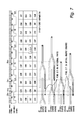
- FIG. 4 is a diagram for describing an example of the switch operation of the drive cam in a normal state of an engine according to the first embodiment of the present disclosure.
- the switch operation of the drive cam is executed in response to a switch request.
- the switch operation of the drive cam is actually started after a cylinder discrimination in response to the switch request.
- the cylinder discrimination is executed with signals of the crank angle sensor and the cam angle sensor.
- crank angle signal the signal from the crank angel sensor
- the protrusions are provided at intervals of 15° CA. Therefore, the crank angle signal shown in FIG. 4 occurs every time the crank shaft rotates by 15° CA.
- signal of the cam angle sensor is pulsed shape corresponding to protrusions on a cam rotor.
- its first protrusion is provided in a range of 30° to 120°
- its second protrusion is provided in a range of 210° to 240°
- its third protrusion is provided in a range of 300° to 360°.
- the cam angle signal which correspond to the chipped tooth parts of the crank angle signal is either “HI” or “LO”.
- the cylinder discrimination is made as to which of the four strokes the current state of each cylinder is based on the result of the cam angle signal.
- the positions of the protrusions of the crank rotor and the cam rotor are known in advance. Therefore, when the cam angle signal obtained by the chipped tooth part of the crank angle signal is “HI” (120° CA), it can be specified that #1 cylinder is in the expansion stroke, #3 cylinder is in the compression stroke, #4 cylinder is in the intake stroke, and #2 cylinder is in the exhaust stroke.
- cam angle signal obtained by the chipped tooth part of the crank angle signal is “LO” (480° CA)
- LO 480° CA
- crank angle CA 0 Assume that the switch request for the drive cam is issued at crank angle CA 0 shown FIG. 4 . Then, the cylinder discrimination is executed based on the cam angle signal “LO” Which is obtained immediately after the crank angle CA 0 due to the chipped tooth part (crank angle CA 1 ). After the cylinder discrimination, the switch operation of the drive cam in #3 cylinder is executed at the crank angle CA 2 . Also, in accordance with an ignition order of the engine, the switch operations in the other cylinders are executed at crank angle CA 3 (#4 cylinder), crank angle CA 4 (#2 cylinder) and crank angle CA 5 (#1 cylinder). Each of the switch operation of the drive cam is finished at crank angle CA 6 (#3 cylinder), crank angle CA 7 (#4 cylinder), crank angle CA 8 (#2 cylinder) and crank angle CA 9 (#1 cylinder).
- the small cam In the system in which the small cam is mainly driven during the normal state of the engine, it is assumed that the small cam is selected as the drive in many cases where a stop request for the engine (a stop request for driving the fuel injector and the ignition device, the same shall apply hereinafter) is issued. Therefore, in the first embodiment, it is determined whether or not a cylinder to which the small cam is selected as the drive cam (hereinafter, also referred to as a “small cam cylinder”) is included when the stop request for the engine is issued. And, when it is determined that the small cam cylinder is included, the switch request for the drive cam is issued. Hereinafter, such control during the engine stop is also called “stop control”. In the stop control of the first embodiment, the switch request for the drive cam is issued for all for all of the solenoid actuators. Based on the switch request, the switch operation of the drive cam described in FIG. 4 is executed.
- a stop request for the engine a stop request for driving the fuel injector and the ignition device, the same shall apply hereinafter
- FIGS. 5 and 6 each are a diagram for describing an example of a processing routine relevant to the start control executed by the ECU in the first embodiment of the present disclosure.
- the routine shown in FIG. 5 is executed in every time when the start request for the engine is issued. Note that the presence or absence of the start request is determine based on, for example, whether or not the ECU has received the IG signal from the ignition key 46 shown in FIG. 1 .
- the IG signal is output when a predetermined operation (for example, the ignition key 46 is turned to a predetermined position) is executed by a driver of the vehicle.
- Step S 10 it is determined whether or not the drive cam is switched to a starting cam (that is, the large cam) in all the cylinders.
- the determination in Step S 10 is executed by using the detection result of the return signal in the stop control executed just before the execution of this routine. Specifically, when the return signal is detected in all the solenoid actuators, it is determined that the drive cam has been switched to the starting cam in all the cylinders. Otherwise, it is determined that failure of switchover of drive cam in the stop control has occurred.
- Step S 10 When the determination result of Step S 10 is positive, it is estimated that there is no small cam cylinder. Therefore, in this case, the engine start is permitted (Step S 12 ). Specifically, drive of the fuel injector and the ignition device in each cylinder is permitted. On the other hand, when the determination result of Step S 10 is negative, it is estimated that at least one of the cylinder corresponds to the small cam cylinder. Therefore, in this case, the switch request for the drive cam is issued (Step S 14 ). Details of a processing based on the switch request will be described with reference to FIG. 6 .
- Step S 16 it is determined whether the completion of the retraction operation has been detected.
- the processing in Step S 16 is executed by using the detection result of the return signal after the processing in Step S 14 .
- the determination result of Step S 16 is positive, it is estimated that the switch operation of the drive cam has been completed in one of the cylinders. Therefore, in this case, the ECU proceeds to Step S 12 .
- the cam carrier continues to rotate in the start control. Therefore, in the start control, the switch operation of the drive cam in each cylinder is executed one after another according to the ignition order.
- the determination result of Step S 16 is positive, the engine start is permitted without waiting for the completion of the switch operation of the drive cam in all cylinders (Step S 12 ).
- the routine shown in FIG. 6 is not only executed when the start request for the engine is issued, but also is repeatedly executed at every predetermined control cycle (for example, every 15° CA).
- Step S 18 it is determined whether or not there is the switch request for the drive cam.
- Step S 20 it is determined whether or not the present processing is executed during the engine start.
- the processing in Step S 20 is determined based on, for example, an elapsed time from which the ECU receives the IG signal.
- the predetermined time for example, 1 sec
- Step S 24 the cylinder discrimination processing.
- the cylinder discrimination processing it is specified which of the four strokes the current state of each cylinder is.
- a start crank angle of the ejection operation is specified that allows the pin to be seated on the orthogonal part of the groove 18 b (or the groove 18 c ) in the “pin insertion section” described in FIG. 3 (Step S 26 ).
- the ejection operation of the pin is started when the crank angle has a match to the specified start crank angle (Step S 28 ).
- Step S 30 it is determined whether or not the completion of the retraction operations of the pins in all the cylinders is detected (Step S 30 ).
- the processing in Step S 30 is executed by using the detection result of the return signal after the processing in Step S 28 .
- the determination result of Step S 30 is negative, the ECU returns to the processing in Step S 24 .
- the determination result of Step S 20 is positive, it is estimated that the switch operation of the drive cam has been completed in all the cylinders. Therefore, in this case, the ECU leaves this routine.
- FIG. 7 is a diagram for describing an example of the switch operation of the drive cam during an engine start according to the first embodiment of the present disclosure.
- the switch operation of the drive cam during the engine start is executed in response to the switch request.
- the ejection operations of the pins at all the solenoid actuators are started at crank angle CA 10 at which the switch request for the drive cam is issued. That is, the ejection operations of the pins are started without waiting for the detection of the cam angle signal at crank angle CA 11 which is obtained immediately after the crank angle CA 10 due to the chipped tooth part.
- the ejected pin sits on the cam carrier at the crank angle CA 12 .
- the ejected pin does not sit on the cam carrier at the crank angle CA 10 because the starter is started to drive at the crank angle CA 10 and the cam carrier rotates thereafter.
- the pins of the solenoid actuators of #2 cylinder and #4 cylinder are seated on the spiral-shaped groove.
- the pins of the solenoid actuators of #1 cylinder and #3 cylinder are seated on an outer periphery of the cam carrier without sitting on the spiral-shaped groove.
- the pin that is seated on the spiral-shaped groove or seated on the outer periphery of the cam carrier and the entered into the spiral-shaped groove moves along the groove in accordance with the rotation of the cam carrier.
- the earliest finish timing of the switch operation of the drive cam is at crank angle CA 13 (#4 cylinder).
- crank angle CA 13 (#4 cylinder)
- drive of the fuel injector and the ignition device in each cylinder is permitted.
- injection from the fuel injector of the #4 cylinder is executed in crank angle on a retard side relative to the crank angle CA 13 , and then the first combustion is occurred in the same #4 cylinder.
- the first combustion may be occurred in #3 cylinder instead of #4 cylinder depending on injection timing of the fuel injector.
- FIG. 8 is a diagram for describing a problem in a case where it is assumed that the switch operation in the normal state of the engine described with reference to FIG. 4 is performed during the engine start.
- the switch request for the drive cam is issued at crank angle CA 10 like the case shown in FIG. 7 .
- the cylinder discrimination is executed.
- the switch operation of the drive cam of #3 cylinder is started.
- the switch operations in the other cylinders are started at crank angle CA 15 (#4 cylinder), crank angle CA 16 (#2 cylinder) and crank angle CA 17 (#1 cylinder).
- crank angle CA 18 (#3 cylinder).
- drive of the fuel injector and the ignition device in each cylinder is permitted.
- injection from the fuel injector of the #3 cylinder is executed in crank angle on a retard side relative to the crank angle CA 18 , and then the first combustion is occurred in the same #3 cylinder.
- the switch operation described with reference to FIG. 4 is executed at the engine start, it takes time until the first combustion takes place.
- the completion of the retraction operation of the pin can be detected at the crank angle CA 13 described with reference to FIG. 7 . That is, the completion of the retraction operation of the pin can be detected with crank angle on an advance angle side of the crank angle CA 18 described with reference to FIG. 8 . Therefore, according to the start control of the first embodiment, it is possible to make the engine to occur the first combustion earlier (for example, about 400 ms) than a case where the switch operation of the drive cam is executed likewise the normal state of the engine.
- FIG. 9 is a diagram for describing another example of the switch operation of the drive cam during the engine start according to the first embodiment of the present disclosure.
- the switch operations of the drive cams in #2 cylinder and #4 have been finished at the issue of the switch request is issued i.e. at the crank angle CA 10 .
- the switch operations in these cylinders was completed in the stop control during the engine stop just before the current engine start.
- the pins which are ejected at the crank angle CA 10 are seated on the cam carriers at crank angle CA 12 .
- the pin of the solenoid actuator of #1 cylinder or #3 cylinder does not sit on the spiral-shaped groove but is seated on the outer periphery of the cam carrier.
- the pin seated on the outer periphery of the cam carrier moves along the outer periphery in accordance with the rotation of the cam carrier and then enters into the spiral-shaped groove from the end portion thereof. Up to this point is the same as the example described with reference to FIG. 7 .
- the pin of the solenoid actuator of #4 cylinder sits on the outer periphery of the cam carrier at the crank angle CA 12 .
- the pin of the solenoid actuator of #4 cylinder moves around the outer periphery in accordance with the rotation of the cam carrier and then enters into the spiral-shaped portion from a joint portion thereof.
- the pin of the solenoid actuator of #2 cylinder sits on the shallow end portion which locates on the rear side in the rotational direction than the joint portion, and then goes back to the solenoid actuator side by the push from the shallow end portion.
- crank angle CA 19 (#2 cylinder).
- injection from the fuel injector of the #2 cylinder is executed in crank angle on a retard side relative to the crank angle CA 19 , and then the first combustion is occurred in the same #2 cylinder.
- the crank angle CA 19 is located on an advance side relative to the crank angle CA 18 described in FIG. 8 .
- the completion of the retraction operation of the pin can be detected at earlier crank angle than the crank angle CA 18 described in FIG. 8 . Therefore, it is possible to make the engine to occur the first combustion earlier than a case where the switch operation of the drive cam is executed likewise the normal state of the engine.
- the orthogonal part of the groove 18 b or groove 18 c described in FIG. 1 corresponds to the “front orthogonal part” of the present disclosure.
- the inclined part of the groove 18 b or groove 18 c corresponds to the “inclined part” of the present disclosure.
- the solenoid actuator 24 corresponds to the “switch mechanism” of the present disclosure.
- the ECU corresponds to the “control device” of the present disclosure.
- the starter motor corresponds to the “motor” of the present disclosure.
- FIG. 10 a configuration example of a system in the second embodiment is common to the configuration example shown in FIG. 1 .
- the rotation operation of the cam carrier and the switch operation of the drive cam are as described in FIGS. 2 to 4 . Therefore, the descriptions about the system configuration example, the rotation operation of the cam carrier and the switch operation of the drive cam are omitted.
- the switch request when the switch request is issued, the ejection operations of the pins at all the solenoid actuators are simultaneously started.
- a switch request is issued after the determination on the small cam cylinder has executed.
- the determination on the small cam cylinder is executed when the start request for the engine is issued.
- drive of the starter is started based on control which is different from the start control. In the first embodiment, therefore, the ejected pins are seated on the cam carriers which rotate in accordance with the drive of the starter.
- FIG. 10 is a diagram for describing an example of a processing routine relevant to the start control executed by the ECU in the second embodiment of the present disclosure.
- the routine shown in FIG. 10 is a routine which is repeatedly executed at predetermined control intervals (for example, every 15° CA) like the routine shown in FIG. 6 .
- Step S 10 the same processing as the routine shown in FIG. 6 is basically executed.
- Step S 32 when it is determined in Step S 20 that the present processing is executed during the engine start, drive of the starter is set to the waiting state (Step S 32 .)
- the waiting state of the starter is realized for example by stopping power supply from the battery to the starter.
- Step S 34 the ejection operations of the pins at all the solenoid actuators are started simultaneously.
- the processing in Step S 34 is the same as the processing in Step S 22 of FIG. 6 .
- Step S 36 it is determined whether or not a waiting time of the starter exceeds a predetermined time.
- the waiting time is set in advance as a time sufficient for the ejected pin to sit on the outer periphery of the cam carrier (for example, 100 ms).
- the processing in Step S 36 is repeated until a positive determination result is obtained.
- the waiting state of the starter is canceled (Step S 38 ).
- FIGS. 11 to 13 a configuration example of a system in the third embodiment is common to the configuration example shown in FIG. 1 .
- the rotation operation of the cam carrier and the switch operation of the drive cam are as described in FIGS. 2 to 4 . Therefore, the descriptions about the system configuration example, the rotation operation of the cam carrier and the switch operation of the drive cam are omitted.
- FIGS. 11 and 12 each are a diagram for describing an example of a processing routine relevant to the start control executed by the ECU in the third embodiment of the present disclosure.
- the routine shown in FIG. 11 is a routine which is executed in every time when the start request for the engine is issued like the routine shown in FIG. 5 .
- the routine shown in FIG. 12 is a routine which is repeatedly executed at predetermined control intervals (for example, every 15° CA) like the routine shown in FIG. 6 .
- Step S 40 it is determined subsequent to Step S 14 whether or not the completion of the retraction operations of the pins of the second actuator group whose start of the ejection operations of the pins are executed later (for example, the solenoid actuators on #1 cylinder and #3 cylinder) is detected (Step S 40 ).
- the processing in Step S 40 is executed by using the detection result of the return signal just after the execution of the processing in Step S 14 .
- the determination result of Step S 40 is positive, it is the switch operation on the drive cam has been completed in one of the cylinders of the second actuator group. Therefore, in this case, the ECU goes to Step S 12 .
- Step S 42 when it is determined in Step S 20 that the present processing is executed during the engine start, it is determined whether or not electrical load restriction is exists (Step S 42 ).
- the processing in Step S 42 is determined based on whether or not the voltage of the battery feeding the pin of the solenoid actuator is less than a predetermined value, for example.
- Step S 44 the ejection operations of the pins at all the solenoid actuators are simultaneously started (Step S 44 ).
- the processing in Step S 44 is the same as the processing in Step S 22 in FIG. 6 .
- Step S 46 When the determination result of Step S 42 is positive, the ejection operations of the pins of the first actuator group (for example, the solenoid actuators on #2 cylinder and #4 cylinder) are started simultaneously (Step S 46 ).
- the processing in Step S 48 is executed by using the detection result of the return signal after the processing in Step S 46 .
- the processing in Step S 48 is repeated until a positive determination result is obtained.
- the ejection operations of the pins of the second actuator group are started simultaneously (Step S 50 ).
- FIG. 13 is a diagram for describing an example of the switch operation of the drive cam during the engine start according to the third embodiment of the present disclosure.
- the switch operations of the first actuator group that is, the solenoid actuators of #2 cylinder and #4 cylinder
- the crank angle CA 10 at which the switch request for the drive cam is issued. That is, the ejection operations of the pins which correspond to the first actuator group are started without waiting for the detection of the cam angle signal at crank angle CA 11 which is obtained immediately after the crank angle CA 10 due to the chipped tooth part.
- the pins which are ejected at crank angle CA 12 sit on the spiral-shaped grooves at the crank angle CA 12 .
- the ejected pins which sit on the spiral-shaped grooves move along the grooves in accordance with the rotations of the cam carriers.
- the switch operations of the drive cam of the first actuator group are completed at the crank angle CA 13 (#4 cylinder) and the crank angle CA 20 (#2 cylinder).
- the ejection operations of the second actuator group are started simultaneously at crank angle CA 21 on a retard side relative to the crank angle CA 20 .
- the pins which are ejected at the crank angle CA 21 sit on the spiral-shaped grooves at crank angle CA 22 .
- the switch operations of the drive cams of the second actuator group are executed.
- FIG. 1 describes an example in which four cam carriers 12 are arranged on the cam shaft 10 of the straight four-cylinder type engine. That is, an example is described in which the cam carriers 12 are arranged per cylinder. However, the cam carrier 12 may be arranged across two or more cylinders. That is, the cam carrier 12 may be arranged per cylinder group. Such an arrangement example is disclosed in JP 2009-228543 A.
- the cam carrier 12 shown in FIG. 1 has two types of intake cams 14 and 16 and the drive cam is switched by the two pins 20 and 22 .
- the cam carrier may have three or more intake cams.
- the starting cam for example, the large cam
- the starting cam needs to be provided between the other two cams.
- FIG. 14 is a diagram for describing a cam carrier including three types of intake cams and a configuration of a solenoid actuator to be combined with the cam carrier.
- the cam carrier 50 shown in FIG. 14 has a small cam 52 , a large cam 54 and a middle cam 56 in an adjacent state.
- the spiral-shaped groove 18 is formed on the surface of the cam carrier 50 .
- the configuration of the groove 18 is as described in FIG. 1 .
- the solenoid actuator 58 combined with the cam carrier 50 has three pins 60 , 62 , 64 and a coil (not shown).
- FIG. 15 is a diagram for describing an example of a switch operation of the drive cam during the engine start on the premise of the cam carrier shown in FIG. 14 .
- the switch request of the drive cam is issued, the ejection operation of the pin 62 is started.
- a cam which was the drive cam immediately before the start request is issued to the engine (hereinafter referred to as a “cam prior to the starting cam”) is the small cam 52 , the drive cam is switched from the small cam 52 to the large cam 54 in accordance with the movement of the pin 62 from the groove 18 b to the groove 18 a (left example of FIG. 15 ).
- the drive cam does no switched because the pin 62 seated on the outer periphery of the cam carrier enters into the groove 18 a from the joint portion and then moves to the groove 18 a (middle example of FIG. 15 ).
- the cam prior to the starting cam is the middle cam 56
- the drive cam is switched from the middle cam 56 to the large cam 54 in accordance with the movement of the pin 62 from the groove 18 c to the groove 18 a (right example of FIG. 15 ).
- the first to the third embodiments of the present disclosure can be worked through the arrangement of the configuration in the cam carriers and the solenoid actuators.
Landscapes
- Engineering & Computer Science (AREA)
- General Engineering & Computer Science (AREA)
- Mechanical Engineering (AREA)
- Chemical & Material Sciences (AREA)
- Combustion & Propulsion (AREA)
- Output Control And Ontrol Of Special Type Engine (AREA)
- Valve Device For Special Equipments (AREA)
- Combined Controls Of Internal Combustion Engines (AREA)
- Electrical Control Of Air Or Fuel Supplied To Internal-Combustion Engine (AREA)
Abstract
Description
Claims (6)
Applications Claiming Priority (2)
| Application Number | Priority Date | Filing Date | Title |
|---|---|---|---|
| JP2017057792A JP6465135B2 (en) | 2017-03-23 | 2017-03-23 | Internal combustion engine system |
| JP2017-057792 | 2017-03-23 |
Publications (2)
| Publication Number | Publication Date |
|---|---|
| US20180274393A1 US20180274393A1 (en) | 2018-09-27 |
| US10329962B2 true US10329962B2 (en) | 2019-06-25 |
Family
ID=63449906
Family Applications (1)
| Application Number | Title | Priority Date | Filing Date |
|---|---|---|---|
| US15/877,437 Expired - Fee Related US10329962B2 (en) | 2017-03-23 | 2018-01-23 | Internal combustion engine system |
Country Status (3)
| Country | Link |
|---|---|
| US (1) | US10329962B2 (en) |
| JP (1) | JP6465135B2 (en) |
| DE (1) | DE102018106665B4 (en) |
Citations (4)
| Publication number | Priority date | Publication date | Assignee | Title |
|---|---|---|---|---|
| US7472671B2 (en) * | 2004-07-30 | 2009-01-06 | Schaeffler Kg | Valve engine |
| JP2009228543A (en) | 2008-03-21 | 2009-10-08 | Toyota Motor Corp | Variable valve train of internal combustion engine |
| JP2010168966A (en) | 2009-01-21 | 2010-08-05 | Nissan Motor Co Ltd | Control device for vehicular internal combustion engine |
| JP2013148012A (en) | 2012-01-19 | 2013-08-01 | Toyota Motor Corp | Fuel supplying device of direct injection type internal combustion engine |
Family Cites Families (4)
| Publication number | Priority date | Publication date | Assignee | Title |
|---|---|---|---|---|
| WO2013042227A1 (en) * | 2011-09-21 | 2013-03-28 | トヨタ自動車株式会社 | Variable valve device |
| JP5704115B2 (en) * | 2012-05-14 | 2015-04-22 | 株式会社デンソー | Electromagnetic actuator |
| JP2017005123A (en) * | 2015-06-11 | 2017-01-05 | いすゞ自動車株式会社 | Electromagnetic actuator |
| JP6330768B2 (en) | 2015-09-16 | 2018-05-30 | トヨタ自動車株式会社 | Engine cooling system |
-
2017
- 2017-03-23 JP JP2017057792A patent/JP6465135B2/en not_active Expired - Fee Related
-
2018
- 2018-01-23 US US15/877,437 patent/US10329962B2/en not_active Expired - Fee Related
- 2018-03-21 DE DE102018106665.1A patent/DE102018106665B4/en not_active Expired - Fee Related
Patent Citations (4)
| Publication number | Priority date | Publication date | Assignee | Title |
|---|---|---|---|---|
| US7472671B2 (en) * | 2004-07-30 | 2009-01-06 | Schaeffler Kg | Valve engine |
| JP2009228543A (en) | 2008-03-21 | 2009-10-08 | Toyota Motor Corp | Variable valve train of internal combustion engine |
| JP2010168966A (en) | 2009-01-21 | 2010-08-05 | Nissan Motor Co Ltd | Control device for vehicular internal combustion engine |
| JP2013148012A (en) | 2012-01-19 | 2013-08-01 | Toyota Motor Corp | Fuel supplying device of direct injection type internal combustion engine |
Also Published As
| Publication number | Publication date |
|---|---|
| US20180274393A1 (en) | 2018-09-27 |
| JP2018159343A (en) | 2018-10-11 |
| DE102018106665A1 (en) | 2018-09-27 |
| DE102018106665B4 (en) | 2022-01-20 |
| JP6465135B2 (en) | 2019-02-06 |
Similar Documents
| Publication | Publication Date | Title |
|---|---|---|
| CN110159437B (en) | System and method for engine poppet valve diagnostics | |
| EP2895724B1 (en) | Control device and control method for internal combustion engine | |
| CN102414423B (en) | Control device for internal combustion engine | |
| US20110232607A1 (en) | Control device for internal combustion engine | |
| US7191747B2 (en) | Method for starting an internal combustion engine | |
| US10329962B2 (en) | Internal combustion engine system | |
| US10465573B2 (en) | Internal combustion engine system | |
| US10294835B2 (en) | Internal combustion engine control system | |
| US10030596B2 (en) | Control device for internal combustion engine | |
| US7661412B2 (en) | Method of controlling the start-up of an internal combustion engine | |
| JP2011169228A (en) | Start control device for internal combustion engine | |
| US11008968B2 (en) | Method and system for variable displacement engine diagnostics | |
| JP3634154B2 (en) | Cylinder discrimination method and apparatus for internal combustion engine | |
| CN106121818A (en) | A kind of signal fluted disc and searching and the method for detection piston position | |
| Zibani et al. | Smart start-stop system for a camless engine employing rotary valves | |
| KR20200047157A (en) | Apparatus for engine synchronization and controlling method thereof | |
| JP2018173029A (en) | Control device for internal combustion engine | |
| JP2000265864A (en) | Control device for internal combustion engine | |
| TW201512517A (en) | Engine system and saddle-straddling type motor vehicle |
Legal Events
| Date | Code | Title | Description |
|---|---|---|---|
| AS | Assignment |
Owner name: TOYOTA JIDOSHA KABUSHIKI KAISHA, JAPAN Free format text: ASSIGNMENT OF ASSIGNORS INTEREST;ASSIGNORS:KAWAI, TAKAYOSHI;ADACHI, NORIYASU;SUGIHIRA, SHIGEHIRO;AND OTHERS;SIGNING DATES FROM 20171222 TO 20171225;REEL/FRAME:044701/0178 |
|
| FEPP | Fee payment procedure |
Free format text: ENTITY STATUS SET TO UNDISCOUNTED (ORIGINAL EVENT CODE: BIG.); ENTITY STATUS OF PATENT OWNER: LARGE ENTITY |
|
| STPP | Information on status: patent application and granting procedure in general |
Free format text: NOTICE OF ALLOWANCE MAILED -- APPLICATION RECEIVED IN OFFICE OF PUBLICATIONS |
|
| STPP | Information on status: patent application and granting procedure in general |
Free format text: PUBLICATIONS -- ISSUE FEE PAYMENT VERIFIED |
|
| STCF | Information on status: patent grant |
Free format text: PATENTED CASE |
|
| FEPP | Fee payment procedure |
Free format text: MAINTENANCE FEE REMINDER MAILED (ORIGINAL EVENT CODE: REM.); ENTITY STATUS OF PATENT OWNER: LARGE ENTITY |
|
| LAPS | Lapse for failure to pay maintenance fees |
Free format text: PATENT EXPIRED FOR FAILURE TO PAY MAINTENANCE FEES (ORIGINAL EVENT CODE: EXP.); ENTITY STATUS OF PATENT OWNER: LARGE ENTITY |
|
| STCH | Information on status: patent discontinuation |
Free format text: PATENT EXPIRED DUE TO NONPAYMENT OF MAINTENANCE FEES UNDER 37 CFR 1.362 |
|
| FP | Lapsed due to failure to pay maintenance fee |
Effective date: 20230625 |