US10326519B2 - Communications system bridging wireless from outdoor to indoor - Google Patents
Communications system bridging wireless from outdoor to indoor Download PDFInfo
- Publication number
- US10326519B2 US10326519B2 US15/627,146 US201715627146A US10326519B2 US 10326519 B2 US10326519 B2 US 10326519B2 US 201715627146 A US201715627146 A US 201715627146A US 10326519 B2 US10326519 B2 US 10326519B2
- Authority
- US
- United States
- Prior art keywords
- module
- outside
- outside module
- wireless power
- frequency band
- Prior art date
- Legal status (The legal status is an assumption and is not a legal conclusion. Google has not performed a legal analysis and makes no representation as to the accuracy of the status listed.)
- Active
Links
Images


Classifications
-
- H—ELECTRICITY
- H04—ELECTRIC COMMUNICATION TECHNIQUE
- H04B—TRANSMISSION
- H04B7/00—Radio transmission systems, i.e. using radiation field
- H04B7/14—Relay systems
- H04B7/15—Active relay systems
- H04B7/155—Ground-based stations
- H04B7/15507—Relay station based processing for cell extension or control of coverage area
-
- H—ELECTRICITY
- H02—GENERATION; CONVERSION OR DISTRIBUTION OF ELECTRIC POWER
- H02J—ELECTRIC POWER NETWORKS; CIRCUIT ARRANGEMENTS OR SYSTEMS FOR SUPPLYING OR DISTRIBUTING ELECTRIC POWER; SYSTEMS FOR STORING ELECTRIC ENERGY
- H02J50/00—Circuit arrangements or systems for wireless supply or distribution of electric power
- H02J50/10—Circuit arrangements or systems for wireless supply or distribution of electric power using inductive coupling
-
- H04B5/0037—
-
- H—ELECTRICITY
- H04—ELECTRIC COMMUNICATION TECHNIQUE
- H04B—TRANSMISSION
- H04B5/00—Near-field transmission systems, e.g. inductive or capacitive transmission systems
- H04B5/70—Near-field transmission systems, e.g. inductive or capacitive transmission systems specially adapted for specific purposes
- H04B5/79—Near-field transmission systems, e.g. inductive or capacitive transmission systems specially adapted for specific purposes for data transfer in combination with power transfer
-
- H—ELECTRICITY
- H04—ELECTRIC COMMUNICATION TECHNIQUE
- H04W—WIRELESS COMMUNICATION NETWORKS
- H04W72/00—Local resource management
- H04W72/04—Wireless resource allocation
- H04W72/044—Wireless resource allocation based on the type of the allocated resource
- H04W72/0453—Resources in frequency domain, e.g. a carrier in FDMA
-
- H—ELECTRICITY
- H02—GENERATION; CONVERSION OR DISTRIBUTION OF ELECTRIC POWER
- H02J—ELECTRIC POWER NETWORKS; CIRCUIT ARRANGEMENTS OR SYSTEMS FOR SUPPLYING OR DISTRIBUTING ELECTRIC POWER; SYSTEMS FOR STORING ELECTRIC ENERGY
- H02J50/00—Circuit arrangements or systems for wireless supply or distribution of electric power
- H02J50/20—Circuit arrangements or systems for wireless supply or distribution of electric power using microwaves or radio frequency waves
Definitions
- the invention is related to wireless communications and in particular to a communications system for bridging wireless from outdoor to indoor.
- Wi-Fi Wireless Fidelity
- WAN wide area network
- LAN local area network
- Wi-Fi Wi-Fi is generally used indoors as a short-range wireless extension of wired broadband systems.
- the 4G LTE systems on the other hand provide wide area long-range connectivity both outdoors and indoors using dedicated infrastructure such as cell towers and backhaul to connect to the Internet.
- millimeter wave frequencies radio spectrum use is lighter, and very wide bandwidths along with a large number of smaller antennas can be used to provide the orders of magnitude increase in capacity needed in the next 15 to 20 years.
- the smaller size of antennas is enabled by carrier waves that are millimeters long compared to centimeter-long waves at currently used lower frequencies.
- a drawback of millimeter waves frequencies is that they tend to lose more energy than do lower frequencies over long distances because they are readily absorbed or scattered by gases, rain, and foliage. Millimeter waves also experience higher losses when penetrating through structures such as walls or any other building materials.
- a wireless communications system includes an outside module configured to communicate with a radio base station.
- the outside module includes a wireless power receiver.
- the system includes an inside module configured to communicate with the outside module and to communicate with a communications device.
- the inside module includes a wireless power transmitter configured to wirelessly transmit power to the outside module.
- the inside module is configured to operate as a wireless extender by transferring signals between the outside module and a communication device.
- a wireless communications system includes an outside module configured to communicate with a radio base station at a first frequency in the uplink direction and at a second frequency in the downlink direction.
- the outside module includes a wireless power receiver.
- the system includes an inside module configured to communicate with the outside module at a third frequency and to communicate with a communications device at a fourth frequency.
- the inside module includes a wireless power transmitter configured to wirelessly transmit power to the outside module.
- the second frequency is in the millimeter wave frequency band and the first, third and fourth frequencies are in the sub-6 GHz bands.
- FIG. 1 illustrates a wireless communications system in accordance with disclosed embodiments.
- FIG. 2 illustrates outside to inside penetration of radio signals by an intermediate node in accordance with disclosed embodiments.
- FIG. 3 illustrates an intermediate node installed in a window.
- FIGS. 4-17 illustrate other disclosed embodiments.
- FIGS. 18 and 19 illustrate multi sub-band selections in accordance with disclosed embodiments.
- FIG. 1 illustrates a wireless communications system 100 in accordance with disclosed embodiments.
- the system 100 enables Gigabits per second access to fixed and mobile users both outdoors and indoors using a single network as illustrated in FIG. 1 .
- the system 100 includes radio base stations 104 and 108 capable of supporting an aggregate data capacity of hundreds of Gigabits per second serving a plurality fixed and mobile users at data speeds in excess of Gigabits/s.
- the radio base stations 104 and 108 are connected to the Internet 112 via a wired link 116 (e.g. fiber optical link) designed to handle aggregate data from multiple radio base stations.
- a wired link 116 e.g. fiber optical link
- FIG. 2 illustrates an intermediate node 200 according to disclosed embodiments.
- the intermediate node 200 allows outside to inside penetration of radio signals.
- the intermediate node 200 refers to the communications link between an outside module 208 and an inside module 216 .
- the functionality of the intermediate node 200 is split across a wall 204 separating the outside and inside environments.
- the wall 204 may be structure of a building that separates the inside environment from the outside environment.
- the wall 204 may be a structure that separates the inside compartment of a vehicle from the outside environment.
- the outside module 208 communicates with a radio base station 212 while the inside module 216 communicates with a communication device 220 inside.
- the inside and outside modules 216 and 208 communicate with each other using either wired or another wireless link.
- the communication device 220 inside a building or a vehicle can access the Internet without requiring a wired Internet connection such as DSL, Cable or FTTH.
- the intermediate node 200 is installed in a glass window 304 of a home or building as illustrated in FIG. 3 .
- the outside module 208 is attached to the outer side of the glass window 304 while the inside module 216 is attached to the inner side of the glass window 304 .
- the inside module 216 is connected to a power source 312 inside the home or building.
- the outside module 208 is powered by the inside module 216 using a wireless power transfer mechanism based on resonant or non-resonant inductive coupling methods.
- the data link between the two modules uses wireless communication. Thus, there is no need to drill holes or run any wires for power or communication with the outside module.
- FIG. 4 illustrates the intermediate node installed in the window of a home or building where the inside unit 216 is powered by an inside power-over-Ethernet (PoE) source 404 and outdoor unit 208 powered by the inside unit wirelessly.
- PoE inside power-over-Ethernet
- This configuration allows a wireless router (not shown in FIG. 4 ) to be connected to the inside unit 216 via an Ethernet cable that carries both power and data.
- the intermediate node may be installed on the side or roof of a vehicle.
- the outside module 208 may be attached to the outer side of a glass window or a windshield while the inside module 216 may be attached to the inner side.
- the inside module 216 is connected to a power source inside the vehicle.
- the outside module 208 is powered by the inside module using a wireless power transfer mechanism based on resonant or non-resonant inductive coupling methods.
- the data link between the two modules uses wireless communication. Thus, there is no need to drill holes or run any wires for power or communication with the outside module.
- FIG. 5 illustrates communications and wireless power transfer functions implemented in the intermediate node 200 .
- the outside module 208 implements communication transceivers 504 and 508 , antennas 512 and 516 , and a wireless power receiver 518 .
- the outside module 208 communicates with the radio base station 104 using the communication transceiver 504 and antenna 512 , and communicates with the inside module 216 using the communication transceiver 508 and antenna 516 .
- the inside module 216 implements communication transceivers 520 and 524 and antennas 528 and 532 .
- the inside module 216 communicates with the outside module 208 using the communication transceiver 520 and the antenna 528 , and communicates with communication devices inside the home, building or a car using the communication transceiver 524 and the antenna 532 .
- the inside module is connected to the power source inside the home, car or building and includes a wireless power transmitter 540 .
- the other functions implemented by the modules are baseband processing, communications protocol processing and wireless power transfer protocol processing.
- FIG. 6 illustrates another embodiment in which transmit and receive coils 604 and 608 for wireless power are aligned on the inside and outside modules 216 and 208 to maximize the power transfer efficiency.
- the same number and same size of the transmit and receive coils 604 and 608 are used. In alternate embodiments, the number and sizes of the transmit and receive coils can be different.
- the outside module 208 communicates at a first frequency f 1 with the radio base station 104 and at a second frequency f 2 with the inside module 216 as shown in FIG. 7 .
- the inside module further communicates at a third frequency f 3 with a communication device 704 inside the home, building or a car.
- all the three frequencies can be the same or any two of the three frequencies can be the same.
- the outside module 208 communicates at a first frequency f 1 with the radio base station 104 and at a second frequency f 2 with the inside module 216 and a communication device 804 inside as illustrated in FIG. 8 .
- the inside module 216 includes a wireless power transmitter 904 which transmits power to a wireless power transmitter 908 in the outside module 208 .
- the inside module 216 is used as a wireless power transmitter to the outside module 208 .
- the third frequency f 3 is equal to f 2 servicing the same protocol with the communication device 912 inside the home, building or a car.
- the outside module 208 communicates at a first frequency f 1 with the radio base station 104 and at a second frequency f 2 with the inside devices.
- the outside module 208 performs direct radio frequency (RF) conversion between f 1 and f 2 without baseband processing.
- the inside module 216 is used as a wireless power transmitter to the outside module while the third frequency f 3 is equal to f 2 servicing the same protocol with the communication devices inside the home, building or a car.
- the inside module 216 is used as a wireless power transmitter to the outside module while the third frequency f 3 is equal to f 2 and f 1 servicing the same protocol with the communication devices inside the home, building or a car as shown in FIG. 11 .
- the outside module 208 is used as a repeater or extender for the communication between the base station 104 and the devices 216 and 1104 .
- the outside and the inside modules 208 and 216 communicate with each other using optical wireless communications 1204 .
- the two modules 208 and 216 are separated by a medium such as glass 1208 that is transparent to optical waves.
- FIG. 13 illustrates another embodiment of the invention wherein the outside module 208 and the inside module 216 communicate using optical wireless communications.
- the outside module 208 and the inside module 216 include light emitting diodes (LED) 1304 and 1308 as transmitters and photodiodes 1312 and 1316 (PD) as receivers.
- LED light emitting diodes
- PD photodiodes
- laser diodes (LD) may be used instead of light emitting diodes.
- the outside and the inside modules 208 and 216 communicate with each other using both wireless and/or optical wireless communications using infrared (IR) wavelengths.
- IR infrared
- FIGS. 14 and 15 illustrate another embodiment of the invention wherein the outside module 208 communicates at both first frequency f 1 and fourth frequency f 4 with the radio base station 104 while communicating between the outside and inside modules 208 and 216 with the second frequency f 2 or optical (visible light or IR), and at a third frequency f 3 with the inside communication devices 1404 .
- the inside module 216 is used as a wireless power transmitter to the outside module 208 while the first frequency f 1 can be used as receiving only from the base station 104 and the fourth frequency f 4 can be used as transmitting only to the radio base station 104 .
- the link with the base station 104 can involve receiving signal from the base station using f 1 and process the data through the outside module 208 only and send a signal back to the base station 104 using f 4 with or without involving the rest of the frequencies f 2 or f 3 .
- a link may utilize a Request-To-Send (RTS) received from the base station 104 and a Clear-To-Send (CTS) protocols from the outside module 208 back to the base station.
- RTS Request-To-Send
- CTS Clear-To-Send
- the outside module 208 communicates at both first frequency f 1 and fourth frequency f 4 with the radio base station 104 while communicating between the outside and inside modules 208 and 216 with the second frequency f 2 or optical (visible light or IR), and at a first frequency f 1 with the inside communication devices 1604 .
- the inside module 216 is used as a wireless power transmitter to the outside module 208 while the first frequency f 1 can be used as receiving only from the base station 104 and the fourth frequency f 4 can be used as transmitting only to the radio base station 104 .
- the link with the base station 104 can involve receiving signal from the base station 104 using f 1 and process the data through the outside module 208 only and send a signal back to the base station 104 using transmitter 4 a and frequency f 4 .
- the inside module 216 converts the signal back to f 1 in order to communicate with communication devices 1604 and vice versa.
- the outside and the inside modules 208 and 216 may include band selection mechanisms that select the frequency sub-bands within f 1 , f 2 , and f 3 .
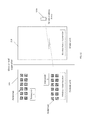
- Each of the f 1 , f 2 , and f 3 frequency bands may include multiple sub-bands within a total of a frequency bandwidth supported by the f 1 , f 2 , and f 3 frequency carriers. Referring to FIG. 18 , there are six sub-bands in f 1 band, four sub-bands in f 2 band, and eight sub-bands in f 3 band.
- Each of the bands in the different frequencies can have different bandwidth.
- the sub-bands in the different frequency bands can have different bandwidth. Hence, conversion from one frequency band to another may not result in occupying the full sub-band bandwidth.
- the outside and the inside modules 208 and 216 may include band selection mechanisms that select the f 1 , f 2 , and f 3 frequency sub-bands where the frequency band conversion requires more than one sub-band in some of the frequency bands as shown in FIG. 19 .
- the conversion from f 2 to f 3 requires occupying more than one sub-band in f 3 band.
- machine usable/readable or computer usable/readable mediums include: nonvolatile, hard-coded type mediums such as read only memories (ROMs) or erasable, electrically programmable read only memories (EEPROMs), and user-recordable type mediums such as floppy disks, hard disk drives and compact disk read only memories (CD-ROMs) or digital versatile disks (DVDs).
- ROMs read only memories
- EEPROMs electrically programmable read only memories
- user-recordable type mediums such as floppy disks, hard disk drives and compact disk read only memories (CD-ROMs) or digital versatile disks (DVDs).
Landscapes
- Engineering & Computer Science (AREA)
- Computer Networks & Wireless Communication (AREA)
- Signal Processing (AREA)
- Power Engineering (AREA)
- Mobile Radio Communication Systems (AREA)
Abstract
Description
Claims (19)
Priority Applications (1)
| Application Number | Priority Date | Filing Date | Title |
|---|---|---|---|
| US15/627,146 US10326519B2 (en) | 2016-07-16 | 2017-06-19 | Communications system bridging wireless from outdoor to indoor |
Applications Claiming Priority (2)
| Application Number | Priority Date | Filing Date | Title |
|---|---|---|---|
| US201662363222P | 2016-07-16 | 2016-07-16 | |
| US15/627,146 US10326519B2 (en) | 2016-07-16 | 2017-06-19 | Communications system bridging wireless from outdoor to indoor |
Publications (2)
| Publication Number | Publication Date |
|---|---|
| US20180019798A1 US20180019798A1 (en) | 2018-01-18 |
| US10326519B2 true US10326519B2 (en) | 2019-06-18 |
Family
ID=60941392
Family Applications (1)
| Application Number | Title | Priority Date | Filing Date |
|---|---|---|---|
| US15/627,146 Active US10326519B2 (en) | 2016-07-16 | 2017-06-19 | Communications system bridging wireless from outdoor to indoor |
Country Status (1)
| Country | Link |
|---|---|
| US (1) | US10326519B2 (en) |
Cited By (4)
| Publication number | Priority date | Publication date | Assignee | Title |
|---|---|---|---|---|
| US11056780B2 (en) * | 2017-11-29 | 2021-07-06 | Verizon Patent And Licensing Inc. | Window-mounted antenna unit |
| US11172544B1 (en) * | 2020-07-24 | 2021-11-09 | Inseego Corp. | Systems and methods for transferring wireless power and data for a 5G wireless access point |
| US11202335B2 (en) * | 2019-02-22 | 2021-12-14 | Nxgen Partners Ip, Llc | Combined tunneling and network management system |
| EP4664794A1 (en) * | 2024-06-13 | 2025-12-17 | T-Mobile USA, Inc. | Communication apparatus across barrier |
Families Citing this family (18)
| Publication number | Priority date | Publication date | Assignee | Title |
|---|---|---|---|---|
| US10374710B2 (en) | 2014-04-04 | 2019-08-06 | Nxgen Partners Ip, Llc | Re-generation and re-transmission of millimeter waves for building penetration |
| EP3542467A4 (en) * | 2016-11-18 | 2020-06-17 | Intel IP Corporation | 5G WIRELESS REMOTE WIRELESS RADIO HEAD SYSTEM |
| JP7366757B2 (en) | 2018-02-05 | 2023-10-23 | パナソニック インテレクチュアル プロパティ コーポレーション オブ アメリカ | Communication system and control method |
| EP3769429B1 (en) * | 2018-03-19 | 2024-11-06 | Pivotal Commware, Inc. | Communication of wireless signals through physical barriers |
| US10382152B1 (en) * | 2018-06-29 | 2019-08-13 | IBT Connect R&D, LLC | Spectrum monitor system and apparatus for radio coverage testing |
| DE102018120779B3 (en) * | 2018-08-24 | 2019-12-12 | Phoenix Contact Gmbh & Co. Kg | Contactless PoE connection system |
| US10522897B1 (en) | 2019-02-05 | 2019-12-31 | Pivotal Commware, Inc. | Thermal compensation for a holographic beam forming antenna |
| US10468767B1 (en) | 2019-02-20 | 2019-11-05 | Pivotal Commware, Inc. | Switchable patch antenna |
| JP2023527384A (en) | 2020-05-27 | 2023-06-28 | ピヴォタル コムウェア インコーポレイテッド | Method for managing RF signal repeater devices for 5G wireless networks |
| US11026055B1 (en) | 2020-08-03 | 2021-06-01 | Pivotal Commware, Inc. | Wireless communication network management for user devices based on real time mapping |
| WO2022056024A1 (en) | 2020-09-08 | 2022-03-17 | Pivotal Commware, Inc. | Installation and activation of rf communication devices for wireless networks |
| CA3208262A1 (en) | 2021-01-15 | 2022-07-21 | Pivotal Commware, Inc. | Installation of repeaters for a millimeter wave communications network |
| AU2022212950A1 (en) | 2021-01-26 | 2023-09-07 | Pivotal Commware, Inc. | Smart repeater systems |
| US11929822B2 (en) | 2021-07-07 | 2024-03-12 | Pivotal Commware, Inc. | Multipath repeater systems |
| WO2023076405A1 (en) | 2021-10-26 | 2023-05-04 | Pivotal Commware, Inc. | Rf absorbing structures |
| WO2023205182A1 (en) | 2022-04-18 | 2023-10-26 | Pivotal Commware, Inc. | Time-division-duplex repeaters with global navigation satellite system timing recovery |
| US20250031192A1 (en) * | 2023-07-21 | 2025-01-23 | T-Mobile Usa, Inc. | Multifunctional, building-edge wireless access point |
| US20250080626A1 (en) * | 2023-09-01 | 2025-03-06 | T-Mobile Usa, Inc. | Protocol translation for building-edge wireless access point |
Citations (41)
| Publication number | Priority date | Publication date | Assignee | Title |
|---|---|---|---|---|
| US6032020A (en) * | 1997-07-28 | 2000-02-29 | Motorola, Inc. | Multi-repeater communication system |
| US20040261432A1 (en) * | 2001-10-26 | 2004-12-30 | Mitsuhiko Yamamoto | Air conditioner control system and air conditioner |
| US20060223561A1 (en) * | 2005-03-31 | 2006-10-05 | Capece Christopher J | Base station bandwidth allocation for extending coverage within a cell |
| US20060267811A1 (en) * | 2005-05-24 | 2006-11-30 | Kan Tan | Method and apparatus for reconstructing signals from sub-band signals |
| US20090111531A1 (en) * | 2007-10-24 | 2009-04-30 | Nokia Corporation | Method and apparatus for transferring electrical power in an electronic device |
| US20090294668A1 (en) * | 2008-05-30 | 2009-12-03 | Searete Llc, A Limited Liability Corporation Of The State Of Delaware | Focusing and sensing apparatus, methods, and systems |
| US20100008287A1 (en) * | 2008-07-11 | 2010-01-14 | Interdigital Patent Holdings, Inc. | System level architectures for relayed uplink communication |
| US20110053632A1 (en) * | 2009-08-25 | 2011-03-03 | Jigang Liu | Antenna transmitting power monitoring and/or controlling |
| US20110050515A1 (en) * | 2009-08-25 | 2011-03-03 | Jigang Liu | Calculating antenna performance |
| US20110053492A1 (en) * | 2008-06-05 | 2011-03-03 | Hochstein Peter A | Networked light control system |
| US20110158156A1 (en) * | 2008-06-02 | 2011-06-30 | Nortel Networks Limited | Method and system using relays with aggregated spectrum |
| US20120116155A1 (en) * | 2010-11-04 | 2012-05-10 | Ethicon Endo-Surgery, Inc. | Light-based, transcutaneous video signal transmission |
| US20120129458A1 (en) * | 2010-11-19 | 2012-05-24 | Raymond Yim | Wireless Communication Network for Transportation Safety Systems |
| US20120322366A1 (en) * | 2011-06-17 | 2012-12-20 | Airwave Solutions Limited | Communications System, Apparatus and Method |
| US20130076577A1 (en) * | 2006-05-30 | 2013-03-28 | Continental Automotive Gmbh | Antenna Module for a Motor Vehicle |
| US20130162471A1 (en) * | 2011-07-12 | 2013-06-27 | Ntt Docomo, Inc. | Positioning support device and positioning support method |
| US20130315109A1 (en) * | 2010-06-21 | 2013-11-28 | Nokia Corporation | Outband/Inband or Full-Duplex/Half-Duplex Mixture Backhaul Signaling in Relay Enhanced Networks |
| US20130329646A1 (en) * | 2011-02-25 | 2013-12-12 | Sharp Kabushiki Kaisha | Wireless communication system, base station device, and wireless communication route selection method |
| US20140159651A1 (en) * | 2012-12-12 | 2014-06-12 | Qualcomm Incorporated | Resolving communcations in a wireless power system with co-located transmitters |
| US20140243043A1 (en) * | 2013-02-26 | 2014-08-28 | Zte (Usa) Inc. | Universal small cell backhaul radio architecture |
| US20150002080A1 (en) * | 2013-06-26 | 2015-01-01 | Robert Bosch Gmbh | Wireless Charging System |
| US20150078497A1 (en) * | 2013-09-13 | 2015-03-19 | Qualcomm Incorporated | Receiver carrier aggregation frequency generation |
| US20150206368A1 (en) * | 2014-01-17 | 2015-07-23 | Wincor Nixdorf International Gmbh | Coin separation device |
| US20150236663A1 (en) * | 2014-02-18 | 2015-08-20 | Viasat, Inc. | Equalization of Frequency-Dependent Gain |
| US20150326378A1 (en) * | 2014-05-09 | 2015-11-12 | Apple Inc. | Spectrum Enhancement and User Equipment Coexistence through Uplink/Downlink Decoupling for Time Division Duplexing and through Non-Continuous Frame Structures for Frequency Division Duplexing |
| US20150350992A1 (en) * | 2014-06-02 | 2015-12-03 | Intel IP Corporation | Communication systems and methods |
| US20160047884A1 (en) * | 2014-08-18 | 2016-02-18 | Qualcomm Incorporated | Using known geographical information in directional wireless communication systems |
| US20160176542A1 (en) * | 2014-12-18 | 2016-06-23 | The Boeing Company | Image capture systems and methods and associated mobile apparatuses |
| US20160248451A1 (en) * | 2015-02-23 | 2016-08-25 | Qualcomm Incorporated | Transceiver configuration for millimeter wave wireless communications |
| US20160262156A1 (en) * | 2013-10-24 | 2016-09-08 | Nokia Technologies Oy | Method and apparatus for adaptive band selection in heterogeneous networks |
| US20160294441A1 (en) * | 2015-03-30 | 2016-10-06 | Futurewei Technologies, Inc. | Copper-Assisted Fifth Generation (5G) Wireless Access to Indoor |
| US20170040827A1 (en) * | 2015-08-06 | 2017-02-09 | Tyco Electronics Corporation | Closure member wireless power system for a closable opening |
| US20170062942A1 (en) * | 2015-09-01 | 2017-03-02 | Hyundai Motor Company | Antenna and vehicle including the same |
| US20170078140A1 (en) * | 2015-09-11 | 2017-03-16 | T-Mobile Usa, Inc. | Automatic network node relay link configuration tool |
| US20170102450A1 (en) * | 2015-10-12 | 2017-04-13 | Navico Holding As | Base Station for Marine Display |
| US20170250566A1 (en) * | 2013-08-19 | 2017-08-31 | Heartware, Inc. | Multiband wireless power system |
| US20170257157A1 (en) * | 2013-12-20 | 2017-09-07 | Solid, Inc. | Base station signal matching device and relay device including the same |
| US20170353337A1 (en) * | 2016-06-03 | 2017-12-07 | Texas Instruments Incorporated | Low latency multi-amplitude modulation receiver |
| US20180026689A1 (en) * | 2016-07-19 | 2018-01-25 | Phazr, Inc. | Systems and Methods for Bandwidth Expansion and Frequency Scaling |
| US9974965B2 (en) * | 2011-09-15 | 2018-05-22 | Micron Devices Llc | Relay module for implant |
| US20180159338A1 (en) * | 2013-08-06 | 2018-06-07 | Energous Corporation | Systems and methods for wirelessly delivering power to electronic devices in response to commands received at a wireless power transmitter |
Family Cites Families (1)
| Publication number | Priority date | Publication date | Assignee | Title |
|---|---|---|---|---|
| US9179056B2 (en) * | 2012-07-16 | 2015-11-03 | Htc Corporation | Image capturing systems with context control and related methods |
-
2017
- 2017-06-19 US US15/627,146 patent/US10326519B2/en active Active
Patent Citations (41)
| Publication number | Priority date | Publication date | Assignee | Title |
|---|---|---|---|---|
| US6032020A (en) * | 1997-07-28 | 2000-02-29 | Motorola, Inc. | Multi-repeater communication system |
| US20040261432A1 (en) * | 2001-10-26 | 2004-12-30 | Mitsuhiko Yamamoto | Air conditioner control system and air conditioner |
| US20060223561A1 (en) * | 2005-03-31 | 2006-10-05 | Capece Christopher J | Base station bandwidth allocation for extending coverage within a cell |
| US20060267811A1 (en) * | 2005-05-24 | 2006-11-30 | Kan Tan | Method and apparatus for reconstructing signals from sub-band signals |
| US20130076577A1 (en) * | 2006-05-30 | 2013-03-28 | Continental Automotive Gmbh | Antenna Module for a Motor Vehicle |
| US20090111531A1 (en) * | 2007-10-24 | 2009-04-30 | Nokia Corporation | Method and apparatus for transferring electrical power in an electronic device |
| US20090294668A1 (en) * | 2008-05-30 | 2009-12-03 | Searete Llc, A Limited Liability Corporation Of The State Of Delaware | Focusing and sensing apparatus, methods, and systems |
| US20110158156A1 (en) * | 2008-06-02 | 2011-06-30 | Nortel Networks Limited | Method and system using relays with aggregated spectrum |
| US20110053492A1 (en) * | 2008-06-05 | 2011-03-03 | Hochstein Peter A | Networked light control system |
| US20100008287A1 (en) * | 2008-07-11 | 2010-01-14 | Interdigital Patent Holdings, Inc. | System level architectures for relayed uplink communication |
| US20110053632A1 (en) * | 2009-08-25 | 2011-03-03 | Jigang Liu | Antenna transmitting power monitoring and/or controlling |
| US20110050515A1 (en) * | 2009-08-25 | 2011-03-03 | Jigang Liu | Calculating antenna performance |
| US20130315109A1 (en) * | 2010-06-21 | 2013-11-28 | Nokia Corporation | Outband/Inband or Full-Duplex/Half-Duplex Mixture Backhaul Signaling in Relay Enhanced Networks |
| US20120116155A1 (en) * | 2010-11-04 | 2012-05-10 | Ethicon Endo-Surgery, Inc. | Light-based, transcutaneous video signal transmission |
| US20120129458A1 (en) * | 2010-11-19 | 2012-05-24 | Raymond Yim | Wireless Communication Network for Transportation Safety Systems |
| US20130329646A1 (en) * | 2011-02-25 | 2013-12-12 | Sharp Kabushiki Kaisha | Wireless communication system, base station device, and wireless communication route selection method |
| US20120322366A1 (en) * | 2011-06-17 | 2012-12-20 | Airwave Solutions Limited | Communications System, Apparatus and Method |
| US20130162471A1 (en) * | 2011-07-12 | 2013-06-27 | Ntt Docomo, Inc. | Positioning support device and positioning support method |
| US9974965B2 (en) * | 2011-09-15 | 2018-05-22 | Micron Devices Llc | Relay module for implant |
| US20140159651A1 (en) * | 2012-12-12 | 2014-06-12 | Qualcomm Incorporated | Resolving communcations in a wireless power system with co-located transmitters |
| US20140243043A1 (en) * | 2013-02-26 | 2014-08-28 | Zte (Usa) Inc. | Universal small cell backhaul radio architecture |
| US20150002080A1 (en) * | 2013-06-26 | 2015-01-01 | Robert Bosch Gmbh | Wireless Charging System |
| US20180159338A1 (en) * | 2013-08-06 | 2018-06-07 | Energous Corporation | Systems and methods for wirelessly delivering power to electronic devices in response to commands received at a wireless power transmitter |
| US20170250566A1 (en) * | 2013-08-19 | 2017-08-31 | Heartware, Inc. | Multiband wireless power system |
| US20150078497A1 (en) * | 2013-09-13 | 2015-03-19 | Qualcomm Incorporated | Receiver carrier aggregation frequency generation |
| US20160262156A1 (en) * | 2013-10-24 | 2016-09-08 | Nokia Technologies Oy | Method and apparatus for adaptive band selection in heterogeneous networks |
| US20170257157A1 (en) * | 2013-12-20 | 2017-09-07 | Solid, Inc. | Base station signal matching device and relay device including the same |
| US20150206368A1 (en) * | 2014-01-17 | 2015-07-23 | Wincor Nixdorf International Gmbh | Coin separation device |
| US20150236663A1 (en) * | 2014-02-18 | 2015-08-20 | Viasat, Inc. | Equalization of Frequency-Dependent Gain |
| US20150326378A1 (en) * | 2014-05-09 | 2015-11-12 | Apple Inc. | Spectrum Enhancement and User Equipment Coexistence through Uplink/Downlink Decoupling for Time Division Duplexing and through Non-Continuous Frame Structures for Frequency Division Duplexing |
| US20150350992A1 (en) * | 2014-06-02 | 2015-12-03 | Intel IP Corporation | Communication systems and methods |
| US20160047884A1 (en) * | 2014-08-18 | 2016-02-18 | Qualcomm Incorporated | Using known geographical information in directional wireless communication systems |
| US20160176542A1 (en) * | 2014-12-18 | 2016-06-23 | The Boeing Company | Image capture systems and methods and associated mobile apparatuses |
| US20160248451A1 (en) * | 2015-02-23 | 2016-08-25 | Qualcomm Incorporated | Transceiver configuration for millimeter wave wireless communications |
| US20160294441A1 (en) * | 2015-03-30 | 2016-10-06 | Futurewei Technologies, Inc. | Copper-Assisted Fifth Generation (5G) Wireless Access to Indoor |
| US20170040827A1 (en) * | 2015-08-06 | 2017-02-09 | Tyco Electronics Corporation | Closure member wireless power system for a closable opening |
| US20170062942A1 (en) * | 2015-09-01 | 2017-03-02 | Hyundai Motor Company | Antenna and vehicle including the same |
| US20170078140A1 (en) * | 2015-09-11 | 2017-03-16 | T-Mobile Usa, Inc. | Automatic network node relay link configuration tool |
| US20170102450A1 (en) * | 2015-10-12 | 2017-04-13 | Navico Holding As | Base Station for Marine Display |
| US20170353337A1 (en) * | 2016-06-03 | 2017-12-07 | Texas Instruments Incorporated | Low latency multi-amplitude modulation receiver |
| US20180026689A1 (en) * | 2016-07-19 | 2018-01-25 | Phazr, Inc. | Systems and Methods for Bandwidth Expansion and Frequency Scaling |
Cited By (4)
| Publication number | Priority date | Publication date | Assignee | Title |
|---|---|---|---|---|
| US11056780B2 (en) * | 2017-11-29 | 2021-07-06 | Verizon Patent And Licensing Inc. | Window-mounted antenna unit |
| US11202335B2 (en) * | 2019-02-22 | 2021-12-14 | Nxgen Partners Ip, Llc | Combined tunneling and network management system |
| US11172544B1 (en) * | 2020-07-24 | 2021-11-09 | Inseego Corp. | Systems and methods for transferring wireless power and data for a 5G wireless access point |
| EP4664794A1 (en) * | 2024-06-13 | 2025-12-17 | T-Mobile USA, Inc. | Communication apparatus across barrier |
Also Published As
| Publication number | Publication date |
|---|---|
| US20180019798A1 (en) | 2018-01-18 |
Similar Documents
| Publication | Publication Date | Title |
|---|---|---|
| US10326519B2 (en) | Communications system bridging wireless from outdoor to indoor | |
| US20240405807A1 (en) | Systems and methods for beam spot alignment on reconfigurable intelligent surface in communication systems | |
| Cudak et al. | Moving towards mmwave-based beyond-4G (B-4G) technology | |
| Sharma et al. | UAV-enabled downlink wireless system with non-orthogonal multiple access | |
| KR101964340B1 (en) | Controller for a suda system | |
| AU2013327697B2 (en) | Systems and methods for wireless backhaul in distributed-input distributed-output wireless systems | |
| US8989155B2 (en) | Systems and methods for wireless backhaul in distributed-input distributed-output wireless systems | |
| US20250096852A1 (en) | Systems and methods for control signaling for using a reconfigurable intelligent surface in communication systems | |
| CN109905886B (en) | Enhanced Customer Premises Equipment | |
| US20030058816A1 (en) | Forwarding communication network and wireless channel allocation method therefor | |
| US7689228B2 (en) | Method and apparatus for providing in-band wireless backhaul | |
| US11930430B2 (en) | Specialized wireless network arrangements for industrial applications | |
| CN108092698A (en) | A kind of wave beam training method and device | |
| EP3829079B1 (en) | Method in a repeater system | |
| KR20170111382A (en) | Base station signal matching device, base station interface unit and distributed antenna system comprising the same | |
| US20060217093A1 (en) | Method and apparatus of a multiple-input-multiple-output wireless system and components | |
| US20180131401A1 (en) | Wireless sfp module | |
| US12095509B2 (en) | Enabling communication with a drone over a wide geographical area using a wireless telecommunication network | |
| CN106937411A (en) | The Miniaturized Communications base station equipment of integrated ONU and household radio router | |
| US20180020451A1 (en) | High Capacity Layered Wireless Communications System | |
| CN104954071B (en) | A kind of digital Optical fiber relay systems of LTE Advanced and its implementation | |
| US10820319B2 (en) | Partitioning a time-division-based communications link for communicating multiple types of communications signals in a wireless distribution system (WDS) | |
| EP2740287B1 (en) | Enhanced rank for outdoor to indoor coverage | |
| EP3228027B1 (en) | Wireless communication network apparatus and method of transmitting communications traffic in simple format | |
| WO2025145979A1 (en) | Communication method and communication apparatus |
Legal Events
| Date | Code | Title | Description |
|---|---|---|---|
| AS | Assignment |
Owner name: PHAZR, INC., TEXAS Free format text: ASSIGNMENT OF ASSIGNORS INTEREST;ASSIGNORS:KHAN, FAROOQ;PISEK, ERAN;DANIELS, ROBERT CLARK;AND OTHERS;SIGNING DATES FROM 20170828 TO 20170928;REEL/FRAME:043747/0784 |
|
| STPP | Information on status: patent application and granting procedure in general |
Free format text: FINAL REJECTION MAILED |
|
| STPP | Information on status: patent application and granting procedure in general |
Free format text: DOCKETED NEW CASE - READY FOR EXAMINATION |
|
| STPP | Information on status: patent application and granting procedure in general |
Free format text: NOTICE OF ALLOWANCE MAILED -- APPLICATION RECEIVED IN OFFICE OF PUBLICATIONS |
|
| FEPP | Fee payment procedure |
Free format text: ENTITY STATUS SET TO UNDISCOUNTED (ORIGINAL EVENT CODE: BIG.); ENTITY STATUS OF PATENT OWNER: LARGE ENTITY |
|
| STCF | Information on status: patent grant |
Free format text: PATENTED CASE |
|
| FEPP | Fee payment procedure |
Free format text: SURCHARGE FOR LATE PAYMENT, LARGE ENTITY (ORIGINAL EVENT CODE: M1554); ENTITY STATUS OF PATENT OWNER: LARGE ENTITY |
|
| MAFP | Maintenance fee payment |
Free format text: PAYMENT OF MAINTENANCE FEE, 4TH YEAR, LARGE ENTITY (ORIGINAL EVENT CODE: M1551); ENTITY STATUS OF PATENT OWNER: LARGE ENTITY Year of fee payment: 4 |