US10323958B2 - Assembly using a magnetic field sensor for detecting a rotation and a linear movement of an object - Google Patents
Assembly using a magnetic field sensor for detecting a rotation and a linear movement of an object Download PDFInfo
- Publication number
- US10323958B2 US10323958B2 US15/074,358 US201615074358A US10323958B2 US 10323958 B2 US10323958 B2 US 10323958B2 US 201615074358 A US201615074358 A US 201615074358A US 10323958 B2 US10323958 B2 US 10323958B2
- Authority
- US
- United States
- Prior art keywords
- magnetic field
- axis
- field sensor
- assembly
- operable
- Prior art date
- Legal status (The legal status is an assumption and is not a legal conclusion. Google has not performed a legal analysis and makes no representation as to the accuracy of the status listed.)
- Active, expires
Links
Images


Classifications
-
- G—PHYSICS
- G01—MEASURING; TESTING
- G01D—MEASURING NOT SPECIALLY ADAPTED FOR A SPECIFIC VARIABLE; ARRANGEMENTS FOR MEASURING TWO OR MORE VARIABLES NOT COVERED IN A SINGLE OTHER SUBCLASS; TARIFF METERING APPARATUS; MEASURING OR TESTING NOT OTHERWISE PROVIDED FOR
- G01D5/00—Mechanical means for transferring the output of a sensing member; Means for converting the output of a sensing member to another variable where the form or nature of the sensing member does not constrain the means for converting; Transducers not specially adapted for a specific variable
- G01D5/12—Mechanical means for transferring the output of a sensing member; Means for converting the output of a sensing member to another variable where the form or nature of the sensing member does not constrain the means for converting; Transducers not specially adapted for a specific variable using electric or magnetic means
- G01D5/14—Mechanical means for transferring the output of a sensing member; Means for converting the output of a sensing member to another variable where the form or nature of the sensing member does not constrain the means for converting; Transducers not specially adapted for a specific variable using electric or magnetic means influencing the magnitude of a current or voltage
- G01D5/142—Mechanical means for transferring the output of a sensing member; Means for converting the output of a sensing member to another variable where the form or nature of the sensing member does not constrain the means for converting; Transducers not specially adapted for a specific variable using electric or magnetic means influencing the magnitude of a current or voltage using Hall-effect devices
- G01D5/145—Mechanical means for transferring the output of a sensing member; Means for converting the output of a sensing member to another variable where the form or nature of the sensing member does not constrain the means for converting; Transducers not specially adapted for a specific variable using electric or magnetic means influencing the magnitude of a current or voltage using Hall-effect devices influenced by the relative movement between the Hall device and magnetic fields
-
- G—PHYSICS
- G01—MEASURING; TESTING
- G01B—MEASURING LENGTH, THICKNESS OR SIMILAR LINEAR DIMENSIONS; MEASURING ANGLES; MEASURING AREAS; MEASURING IRREGULARITIES OF SURFACES OR CONTOURS
- G01B7/00—Measuring arrangements characterised by the use of electric or magnetic techniques
- G01B7/003—Measuring arrangements characterised by the use of electric or magnetic techniques for measuring position, not involving coordinate determination
-
- G—PHYSICS
- G01—MEASURING; TESTING
- G01B—MEASURING LENGTH, THICKNESS OR SIMILAR LINEAR DIMENSIONS; MEASURING ANGLES; MEASURING AREAS; MEASURING IRREGULARITIES OF SURFACES OR CONTOURS
- G01B7/00—Measuring arrangements characterised by the use of electric or magnetic techniques
- G01B7/02—Measuring arrangements characterised by the use of electric or magnetic techniques for measuring length, width or thickness
- G01B7/023—Measuring arrangements characterised by the use of electric or magnetic techniques for measuring length, width or thickness for measuring distance between sensor and object
-
- G—PHYSICS
- G01—MEASURING; TESTING
- G01D—MEASURING NOT SPECIALLY ADAPTED FOR A SPECIFIC VARIABLE; ARRANGEMENTS FOR MEASURING TWO OR MORE VARIABLES NOT COVERED IN A SINGLE OTHER SUBCLASS; TARIFF METERING APPARATUS; MEASURING OR TESTING NOT OTHERWISE PROVIDED FOR
- G01D21/00—Measuring or testing not otherwise provided for
- G01D21/02—Measuring two or more variables by means not covered by a single other subclass
-
- G—PHYSICS
- G01—MEASURING; TESTING
- G01R—MEASURING ELECTRIC VARIABLES; MEASURING MAGNETIC VARIABLES
- G01R33/00—Arrangements or instruments for measuring magnetic variables
- G01R33/02—Measuring direction or magnitude of magnetic fields or magnetic flux
- G01R33/06—Measuring direction or magnitude of magnetic fields or magnetic flux using galvano-magnetic devices
- G01R33/07—Hall effect devices
- G01R33/077—Vertical Hall-effect devices
Definitions
- This invention relates generally to magnetic field sensors, and more particularly, to an assembly that uses a magnetic field sensor for detecting rotation and a linear movement of a movable object.
- Some magnetic field sensors are operable to detect a rotation of an object.
- Other magnetic field sensors are operable to detect a linear movement of an object, whether a straight line movement or a curved motion.
- the present invention provides a magnetic field sensor operable to detect both a rotation and a linear movement of an object.
- an assembly is oriented in an x, y, z Cartesian coordinate system with an x axis, a y axis and a z axis.
- the assembly can include a base structure, wherein x, y, z Cartesian coordinate system does not move relative to the base structure.
- the assembly can further include a rotatable structure moveably disposed with respect to the base structure, wherein the rotatable structure and the base structure are operable to move in a relative movement along a line relative to each other in a direction tangential to the y axis, wherein the rotatable structure is operable to rotate about a rotation axis parallel to the z axis.
- the assembly can further include a first magnet fixedly coupled to the base structure, the first magnet having north and south poles aligned along a first line stationary with respect to the base structure, the first magnet for generating a first magnetic field.
- the assembly can further include a second magnet fixedly coupled to the rotatable structure, the second magnet having north and south poles aligned along a second line rotatable with the rotatable structure, the second magnet for generating a second magnetic field.
- the assembly can further include a magnetic field sensor disposed proximate to the base structure and proximate to the rotatable structure.
- the magnetic field sensor can include at least one magnetic field sensing element for generating at least one sensing element signal responsive to the first and second magnetic fields at a position of the at least one magnetic field sensing element.
- the above magnetic field sensor can further include a position processor coupled to the at least one sensing element signal and operable to generate a position signal indicative of the at least one predetermined combination of the relative movement along the line and the rotation about the rotation axis.
- a magnetic field sensor is for sensing a position of an object, the object operable to move in a relative movement along a line relative to another object and to rotate about a rotation axis.
- the magnetic field sensor can include at least one magnetic field sensing element disposed proximate to the object, the at least one magnetic field sensing element for generating at least one sensing element signal responsive to first and second magnetic fields at a position of the at least one magnetic field sensing element.
- the above magnetic field sensor can further include a position processor coupled to the at least one sensing element signal and operable to generate a position signal indicative of the at least one predetermined combination of the relative movement along the line and the rotation about the rotation axis.
- FIGS. 1-6 are pictorial diagrams of an assembly having a base structure and having a rotatable structure operable to move linearly relative to each other at different relative positions of the base structure and of the rotatable structure, wherein the rotatable structure is further operable to rotate about an axis, the assembly also having first and second magnets and having a magnetic field sensor;
- FIG. 7 is a graph showing an amplitude of a magnetic field experienced at a location of the magnetic field sensors of FIGS. 1-6 and at the different relative positions and rotations of FIGS. 1-6 ;
- FIG. 8 is a truth table showing relationships between a rotating magnetic field along an x direction of FIGS. 1-6 with threshold values and showing corresponding different relative positions and rotations of the base structure and of the rotatable structure of FIGS. 1-6 ;
- FIGS. 9-14 are pictorial diagrams of another assembly having a base structure and having a rotatable structure operable to move linearly relative to each other at different relative positions of the base structure and of the rotatable structure, wherein the rotatable structure is further operable to rotate about an axis, the assembly also having first and second magnets and having a magnetic field sensor;
- FIGS. 15-20 are pictorial diagrams showing the first and second magnets of FIGS. 9-14 , respectively, at the different relative positions and rotations of FIGS. 9-14 and showing two examples of orientations of at least two different types of magnetic field sensors that can be used as the magnetic field sensor of FIGS. 9-14 ;
- FIG. 21 is a graph showing an angle of a magnetic field experienced at a location of the magnetic field sensors of FIGS. 9-20 and at the different relative positions of FIGS. 9-20 ;
- FIG. 22 is a truth table showing relationships between an angle of a magnetic field of FIGS. 9-20 with threshold values and showing corresponding different relative positions and rotations of the base structure and of the rotatable structure of FIGS. 9-20 ;
- FIG. 23 is a graph showing an amplitude of a magnetic field in an x-direction (i.e., a projection of the magnetic field upon an x-axis) experienced at a location of the magnetic field sensors of FIGS. 9-20 , at the different relative positions and rotations of FIGS. 9-20 , and using the first and second magnets of FIGS. 9-20 ;
- FIG. 24 is a graph showing an amplitude of a magnetic field in a y-direction (i.e., a projection of the magnetic field upon a y-axis) experienced at a location of the magnetic field sensors of FIGS. 9-20 , at the different relative positions of FIGS. 9-20 , and using the first and second magnets of FIGS. 9-20 ;
- FIG. 25 is a truth table showing relationships between the directional magnetic fields of FIGS. 23 and 24 with threshold values and showing corresponding different relative positions of the base structure and rotations of the rotatable structure of FIGS. 9-20 ;
- FIG. 26 is a pictorial drawing showing the second magnet and a different first magnet than the first magnet of FIGS. 9-20 , and also showing a magnetic field sensor;
- FIG. 27 is a graph showing an amplitude of a magnetic field in an x-direction (i.e., a projection of the magnetic field upon an x-axis) experienced at a location of the magnetic field sensor of FIGS. 9-20 at the different relative positions and rotations of FIGS. 9-20 and using the second magnet and the different first magnet of FIG. 26 when in physical conditions of FIGS. 9-20 ;
- FIG. 28 is a graph showing an amplitude of a magnetic field in a y-direction (i.e., a projection of the magnetic field upon a y-axis) experienced at a location of the magnetic field sensor of FIGS. 9-20 at the different relative positions of FIGS. 9-20 and using the second magnet and the different first magnet of FIG. 26 when in physical conditions of FIGS. 9-20 ;
- FIG. 29 is a truth table showing relationships between the directional magnetic fields of FIGS. 27 and 28 with threshold values and showing corresponding different relative positions of the base structure and of the rotatable structure of FIGS. 9-20 ;
- FIG. 30 is a block diagram showing an illustrative embodiment of a magnetic field sensor having a planar Hall element and electronic circuits all disposed upon a substrate that can be used as the magnetic field sensors of FIGS. 1-6 and that can provide a magnetic field sensor signal representative of the graph of FIG. 7 ;
- FIG. 31 is a block diagram showing an illustrative embodiment of another magnetic field sensor having a vertical Hall element and electronic circuits all disposed upon a substrate that can be used as the magnetic field sensors of FIGS. 1-6 and that can provide a magnetic field sensor signal representative of the graph of FIG. 7 ;
- FIG. 32 is a block diagram showing an illustrative embodiment of another magnetic field sensor having a circular vertical Hall (CVH) sensing element and electronic circuits all disposed upon a substrate that can be used as one of the magnetic field sensors of FIGS. 9-20 and that can provide a magnetic field sensor signal representative of the graph of FIG. 21 ;
- CVH circular vertical Hall
- FIG. 33 is a block diagram showing an illustrative embodiment of another magnetic field sensor having both a planar Hall element and a vertical Hall element and also electronic circuits all disposed upon a substrate that can be used as one of the magnetic field sensors of FIGS. 9-20 and that can provide a magnetic field sensor signal representative of the graph of FIG. 21 ;
- FIG. 34 is a block diagram showing an illustrative embodiment of another magnetic field sensor having both a planar Hall element and a vertical Hall element and also electronic circuits all disposed upon a substrate that can be used as one of the magnetic field sensors of FIGS. 9-20 and that can provide a magnetic field sensor signal representative of the graphs of FIGS. 23 and 24 or the graphs of FIGS. 27 and 28 .
- magnetic field sensing element is used to describe a variety of electronic elements that can sense a magnetic field.
- the magnetic field sensing element can be, but is not limited to, a Hall effect element, a magnetoresistance element, or a magnetotransistor.
- Hall effect elements for example, a planar Hall element, a vertical Hall element, and a Circular Vertical Hall (CVH) element.
- magnetoresistance elements for example, a semiconductor magnetoresistance element such as Indium Antimonide (InSb), a giant magnetoresistance (GMR) element, for example, a spin valve, an anisotropic magnetoresistance element (AMR), a tunneling magnetoresistance (TMR) element, and a magnetic tunnel junction (MTJ).
- the magnetic field sensing element may be a single element or, alternatively, may include two or more magnetic field sensing elements arranged in various configurations, e.g., a half bridge or full (Wheatstone) bridge.
- the magnetic field sensing element may be a device made of a type IV semiconductor material such as Silicon (Si) or Germanium (Ge), or a type III-V semiconductor material like Gallium-Arsenide (GaAs) or an Indium compound, e.g., Indium-Antimonide (InSb).
- a type IV semiconductor material such as Silicon (Si) or Germanium (Ge)
- a type III-V semiconductor material like Gallium-Arsenide (GaAs) or an Indium compound, e.g., Indium-Antimonide (InSb).
- some of the above-described magnetic field sensing elements tend to have an axis of maximum sensitivity parallel to a substrate that supports the magnetic field sensing element, and others of the above-described magnetic field sensing elements tend to have an axis of maximum sensitivity perpendicular to a substrate that supports the magnetic field sensing element.
- planar Hall elements tend to have axes of sensitivity perpendicular to a substrate
- metal based or metallic magnetoresistance elements e.g., GMR, TMR, AMR
- vertical Hall elements tend to have axes of sensitivity parallel to a substrate.
- magnetic field sensor is used to describe a circuit that uses a magnetic field sensing element, generally in combination with other circuits.
- Magnetic field sensors are used in a variety of applications, including, but not limited to, an angle sensor that senses an angle of a direction of a magnetic field, a current sensor that senses a magnetic field generated by a current carried by a current-carrying conductor, a magnetic switch that senses the proximity of a ferromagnetic object, a rotation detector that senses passing ferromagnetic articles, for example, magnetic domains of a ring magnet or a ferromagnetic target (e.g., gear teeth) where the magnetic field sensor is used in combination with a back-biased or other magnet, and a magnetic field sensor that senses a magnetic field density of a magnetic field.
- an angle sensor that senses an angle of a direction of a magnetic field
- a current sensor that senses a magnetic field generated by a current carried by a current-carrying conductor
- a magnetic switch that
- parallel and perpendicular are used in various contexts herein. It should be understood that the terms parallel and perpendicular do not require exact perpendicularity or exact parallelism, but instead it is intended that normal manufacturing tolerances apply, which tolerances depend upon the context in which the terms are used. In some instances, the term “substantially” is used to modify the terms “parallel” or “perpendicular.” In general, use of the term “substantially” reflects angles that are beyond manufacturing tolerances, for example, within +/ ⁇ ten degrees.
- processor is used to describe an electronic circuit that performs a function, an operation, or a sequence of operations.
- the function, operation, or sequence of operations can be hard coded into the electronic circuit or soft coded by way of instructions held in a memory device.
- a “processor” can perform the function, operation, or sequence of operations using digital values or using analog signals.
- the “processor” can be embodied in an application specific integrated circuit (ASIC), which can be an analog ASIC or a digital ASIC. In some embodiments, the “processor” can be embodied in a microprocessor with associated program memory. In some embodiments, the “processor” can be embodied in a discrete electronic circuit, which can be an analog or digital.
- ASIC application specific integrated circuit
- the “processor” can be embodied in a microprocessor with associated program memory.
- the “processor” can be embodied in a discrete electronic circuit, which can be an analog or digital.
- module is used to describe a “processor.”
- a processor can contain internal processors or internal modules that perform portions of the function, operation, or sequence of operations of the processor.
- a module can contain internal processors or internal modules that perform portions of the function, operation, or sequence of operations of the module.
- a so-called comparator can be comprised of an analog comparator having a two state output signal indicative of an input signal being above or below a threshold level.
- the comparator can also be comprised of a digital circuit having an output signal with at least two states indicative of an input signal being above or below a threshold level.
- the term “predetermined,” when referring to a value or signal, is used to refer to a value or signal that is set, or fixed, in the factory at the time of manufacture, or by external means, e.g., programming, thereafter.
- the term “determined,” when referring to a value or signal, is used to refer to a value or signal that is identified by a circuit during operation, after manufacture.
- linear and “linear” are used to describe either a straight line or a curved line.
- the line can be described by a function having any order less than infinity.
- Magnetic field sensors using planar Hall elements, vertical Hall elements and circular vertical Hall (CVH) sensing elements are described in embodiments below. However, it should be understood that other types of magnetic field sensing elements can also be used in similar magnetic field sensors.
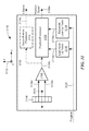
- an example of an assembly 100 shown in six physical conditions (e.g., positions), also referred to herein as states, labeled by boxes A 1 , B 1 , C 1 , D 1 , E 1 , and F 1 , can be oriented in an x, y, z Cartesian coordinate system 120 with an x axis, a y axis and a z axis.
- the assembly 100 can include a base structure 102 , wherein the x, y, z Cartesian coordinate system 120 does not move relative to the base structure 102 .
- the assembly 100 can further include a rotatable structure 108 .
- the rotatable structure 108 and the base structure 102 can be operable to move in a relative movement along a line (e.g., a straight or curved line) relative to each other in a direction parallel to or tangential to the y axis.
- the rotatable structure 108 is also operable to rotate about a rotation axis (out of the page) parallel to the z axis.
- the assembly 100 can further include a first magnet 104 fixedly coupled to the base structure 102 , the first magnet 104 having north and south poles aligned along a first line stationary with respect to the base structure 102 .
- the first magnet 104 is for generating a first magnetic field described more fully in conjunction with other figures below.
- the first magnet 104 has a rectangular or square shape as shown. However, other shapes are possible.
- a line between north and south poles of the first magnet 104 is aligned parallel to the x-axis.
- other alignments of the north and south poles of the first magnet 104 are possible.
- the assembly 100 can further include a second magnet 112 fixedly coupled to the rotatable structure 108 , the second magnet 112 having north and south poles aligned along a second line rotatable with the rotatable structure 108 .
- the second magnet 112 is for generating a second magnetic field described more fully in conjunction with other figures below.
- the second magnet 112 is curved as shown. However, other shapes are possible.
- a line between north and south poles of the second magnet 112 is radially aligned relative to the rotatable structure 108 .
- other alignments of the north and south poles of the second magnet 112 are possible.
- the assembly 100 can further include a magnetic field sensor 110 disposed proximate to the base structure 102 and proximate to the rotatable structure 108 .
- the magnetic field sensor 110 can be fixedly coupled to the rotatable structure 108 (e.g., coupled to a structure 106 ), but does not rotate.
- the magnetic field sensor 110 can include at least one magnetic field sensing element (shown in figures below) for generating at least one sensing element signal responsive to the first and second magnetic fields (i.e., responsive to a vector sum of the magnetic fields) at a position of the at least one magnetic field sensing element in the magnetic field sensor 110 .
- the magnetic field sensor 110 can also include a position processor (shown in figures below) coupled to the at least one sensing element signal and operable to generate a position signal (See, e.g., FIGS. 30 and 31 ) indicative of at least one predetermined combination of the relative movement along the line and the rotation about the rotation axis
- the assembly 100 can have a first physical condition labeled by the box A 1 here and in figures below for which the rotatable structure 108 and the base structure 102 are relatively far apart along a line 114 a parallel to or tangential to the y axis.
- a first rotation angle of the rotatable structure 108 is indicated by an arrow 116 a.
- the assembly 100 can have a second physical condition labeled by the box B 1 here and in figures below for which the rotatable structure 108 and the base structure are closer together along a line 114 b parallel to or tangential to the y axis.
- a second rotation angle of the rotatable structure 108 is indicated by an arrow 116 b , and can, for example, be the same rotation as the first rotation angle 116 a.
- the assembly 100 can have a third physical condition labeled by the box C 1 here and in figures below for which the rotatable structure 108 and the base structure 102 are now further apart along a line 114 c parallel to or tangential to the y axis, as may occur, for example, due to a mechanical disturbance such as a bump in a moving automobile.
- a third rotation angle of the rotatable structure 108 is indicated by an arrow 116 c and can be different than the first and second rotation angles 116 a , 116 b .
- the rotatable structure 108 may have begun to rotate about the z axis as shown.
- the assembly 100 can have a fourth physical condition labeled by the box D 1 here and in figures below for which the rotatable structure 108 and the base structure 102 , as in FIG. 3 , are further apart along a line 114 d parallel to or tangential to the y axis, and for which the rotatable structure 108 has fully rotated about the z axis to a rotation angle indicated by an arrow 116 d.
- the assembly 100 can take on conditions A 1 , B 1 , C 1 , and D 1 in sequence, which may be undesirable.
- an alternative sequence can be achieved when the above-described mechanical disturbance is detected, in which case, the sequence of physical conditions can be A 1 , B 1 , C 1 , A 1 .
- the assembly 100 can have a fifth physical condition labeled by the box E 1 here and in figures below for which the rotatable structure 108 and the base structure 102 remain close together along a line 114 e parallel to or tangential to the y axis as in FIG. 2 .
- the rotatable structure 108 may have begun to rotate about the z axis indicated by a line 116 e.
- the assembly 100 can have a sixth physical condition labeled by the box F 1 here and in figures below for which the rotatable structure 108 and the base structure 102 , as in FIG. 5 , remain close together along a line 114 f parallel to or tangential to the y axis.
- the rotatable structure 108 has fully rotated about the z axis as indicated by a line 116 f.
- the assembly 100 can take on conditions identified by boxes A 1 , B 1 , E 1 , and F 1 in sequence, which may be desirable.
- detection of the conditions identified by the box F 1 may be indicative of a desirable condition.
- the first magnet 104 in combination with the second magnet 112 which can rotate with the rotatable structure 108 , can result in a magnetic field at a position of the magnetic field sensor 110 that can change both angle and amplitude depending upon the six conditions labeled A 1 , B 1 , C 1 , D 1 , E 1 , and F 1 .
- the magnetic field sensor 110 which can be one and only one magnetic field sensor, can detect not only relative position of the rotatable structure 108 to the base structure 102 along a line parallel to or tangential to the y axis, but, at the same time, can also detect a rotation of the rotatable structure 108 about the z axis.
- the magnetic field sensor 110 can detect at least one predetermined combination of the relative movement along the line and the rotation about the rotation axis. In some embodiments, the magnetic field sensor 110 can detect a plurality of predetermined combinations of the relative movement along the line and the rotation about the rotation axis.
- a graph 700 has a vertical axis with a sale in units of magnetic field in Gauss, wherein the magnetic field is an x projection of a vector sum of magnetic fields at a position of the magnetic field sensor 110 of FIGS. 1-6 as may be measured by the magnetic field sensor 110 of FIGS. 1-6 .
- the graph 700 also has a horizontal axis with a scale in units of rotation angle in degrees, wherein the rotation angle is a rotation angle of the rotatable structure 108 of FIG. 1 about the z axis of FIG. 1 .
- Boxes A 1 , B 1 , C 1 , D 1 , E 1 , and F 1 of FIG. 7 are indicative of elements of FIGS. 1-6 at the same physical conditions identified by boxes A 1 , B 1 , C 1 , D 1 , E 1 , F 1 of FIGS. 1-6 .
- a curve 702 is indicative of a progression from among the physical conditions identified by boxes A 1 , B 1 , C 1 , D 1 . As described above, the physical conditions identified by the boxes C 1 and D 1 may be undesirable.
- a curve 704 is indicative of a progression from among the physical conditions identified by boxes A 1 , B 1 , E 1 , and F 1 . As described above, the physical conditions identified by the boxes E 1 and F 1 may be desirable.
- the graph 700 has a vertical axis in units indicative of an x projection of a magnetic field at a position of the magnetic field sensor 110 , it should be appreciated that the vertical axis could instead be indicative of an output voltage from a Hall element, for example, a planar Hall element within the magnetic field sensor 110 of FIGS. 1-6 , having an axis of maximum sensitivity parallel to the x axis.
- the planar Hall element responds to magnetic fields in accordance with an x projection of magnetic fields that it experiences.
- Thresholds 720 , 722 , 724 , 726 can be used in conjunction with FIG. 8 below to identify the predetermined physical condition identified by the boxes labeled A 1 , B 1 , C 1 , D 1 , E 1 , and F 1 . While particular threshold values are shown, other threshold values can also be used, including additional threshold values.
- a threshold magnetic field 708 (i.e., a threshold voltage from the Hall element) can be used to identify a mechanical disturbance in the various physical conditions identified by the blocks A 1 , B 1 , C 1 , D 1 , E 1 , and F 1 .
- the threshold 726 could be used for the same purpose. For example, when a first transition 706 from the physical condition identified by the block A 1 to a physical condition identified by the block B 1 occurs, the x projected magnetic field (and the corresponding Hall element output signal) crosses the threshold 708 in a first direction. At a point 710 , if a mechanical disturbance occurs, the rotatable structure 108 of FIGS.
- 1-6 may move away from the base structure 102 and the x projected magnetic field at the magnetic field sensor 110 may take a path 712 , crossing the threshold 708 in a second different direction. If the magnetic field sensor 110 detects the transition 712 , a processor coupled to the apparatus 100 can revert to the physical condition identified by the box labeled A 1 . The apparatus can then attempt again to follow the desirable conditions identified by blocks A 1 , B 1 , E 1 , and F 1 .
- the rotatable structure 108 may move away from the base structure 102 and the x projected magnetic field at the magnetic field sensor 110 may take a path 716 , which does not cross the threshold 708 in the second different direction, in which case, the assembly 100 eventually arrives at the undesirable condition identified by the box D 1 .
- the magnetic field sensor 110 can identify this condition because a signal generated by the Hall element within the magnetic field sensor 110 has not crossed the threshold 720 .
- a variety of logic can be used to identify if the desirable condition identified by the block F 1 has or has not been achieved (see also FIG. 8 ).
- a time threshold can be used to indicate that the desirable condition has not been achieved prior to a threshold time after initiation of movement represented in boxes A 1 , B 1 , C 1 , D 1 , E 1 , and F 1 , for example, three seconds.
- a rotation detector (not shown) can determine when the rotatable structure 108 has rotated about the z axis by an amount sufficient to achieve the condition identified by the blocks D 1 or F 1 , and the magnetic field sensor 110 can detect that the threshold 720 has not been crossed, thus the undesirable condition identified by the block D 1 has been achieved instead of the desirable condition identified by the block F 1 . The apparatus can then revert to the condition labeled by box A.
- threshold value 708 While a particular threshold value 708 is shown, other threshold values can also be used for the above-described purpose.
- the magnetic field sensor e.g., the magnetic field sensor 100 of FIGS. 1-6 and a magnetic field sensors 3100 , 3200 of FIGS. 31 and 32 , respectively, described below can provide an output signal having values in accordance with values of the graph 700 .
- another processor to which the magnetic field sensor 100 is coupled can make a determination of in which of the conditions identified by boxes A 1 , B 1 , C 1 , D 1 , E 1 , and F 1 the assembly of FIGS. 1-6 is in.
- the magnetic field sensor (see, e.g., FIGS. 31, 32 ) can include a position processor operable to make the above determination and provide a signal indicative of the determination.
- a table 800 has a first column 802 indicative of amplitudes of x projections of a vector sum (see below) of a magnetic field experienced by the magnetic field sensor 110 of FIGS. 1-6 as compared with the first, second, third, and fourth thresholds 726 , 724 , 722 , 720 , respectively, of FIG. 7 .
- the table 800 has a second column 802 indicative of the above described physical conditions of the assembly 100 of FIGS. 1-6 represented by the boxes A 1 , B 1 , C 1 , D 1 , E 1 , F 1 .
- an example of an assembly 900 shown in six physical conditions (e.g., positions), also referred to herein as states, labeled by boxes A 2 , B 2 , C 2 , D 2 , E 2 , and F 2 can be oriented in the same x, y, z Cartesian coordinate system 120 with an x axis, a y axis and a z axis.
- the assembly 900 can include the base structure 102 , wherein the x, y, z Cartesian coordinate system 120 does not move relative to the base structure 102 .
- the assembly 900 can further include the rotatable structure 108 .
- the rotatable structure 108 and the base structure 102 can be operable to move in a relative movement along a line (e.g., a straight or curved line) relative to each other in a direction parallel to or tangential to the y axis.
- the rotatable structure 108 an also operable to rotate about a rotation axis (out of the page) parallel to the z axis.
- rotatable structure 108 can rotate in a direction opposite to directions of rotation indicated in conjunction with FIGS. 1-6 .
- the assembly 900 can further include the first magnet 104 fixedly coupled to the base structure 102 , the first magnet 104 having north and south poles aligned along a first line stationary with respect to the base structure 102 .
- the first magnet 104 is for generating a first magnetic field described more fully in conjunction with other figures below.
- the first magnet 104 has a rectangular or square shape as shown. However, other shapes are possible.
- the assembly 900 can further include a second magnet 904 fixedly coupled to the rotatable structure 108 , the second magnet 904 having north and south poles aligned along a second line rotatable with the rotatable structure 108 .
- the second magnet 904 is for generating a second magnetic field described more fully in conjunction with other figures below.
- the second magnet 904 has a solid rectangular shape as shown. However, other shapes are possible.
- the second magnet 112 of FIGS. 1-6 can be disposed upon or near an outer perimeter of the rotatable structure 108
- the second magnet 904 can be disposed at or near to a center of rotation of the rotatable structure 108 .
- the assembly 900 can further include the magnetic field sensor 110 disposed proximate to the base structure 102 and proximate to the rotatable structure 108 .
- the magnetic field sensor 110 can be fixedly coupled to the rotatable structure 108 (e.g., coupled to a structure 106 ), but does not rotate.
- the magnetic field sensor 110 can include at least one magnetic field sensing element (shown in figures below) for generating at least one sensing element signal responsive to the first and second magnetic fields (i.e., responsive to a vector sum of the magnetic fields) at a position of the at least one magnetic field sensing element in the magnetic field sensor 110 .
- the magnetic field sensor 110 can also include a position processor (shown in figures below) coupled to the at least one sensing element signal and operable to generate a position signal (See, e.g., FIGS. 32-34 ) indicative of at least one predetermined combination of the relative movement along the line and the rotation about the rotation axis.
- FIGS. 9-14 will be understood from discussion above in conjunction with FIGS. 1-6 above and FIGS. 15-20 below.
- the six physical conditions e.g., positions
- states also referred to herein as states, labeled by boxes A 2 , B 2 , C 2 , D 2 , E 2 , and F 2 can rotate in a direction opposite to rotation of the states A 1 , B 1 , C 1 , D 1 , E 1 , and F 1 of FIGS. 1-6 .
- a partial assembly 1500 can include a first magnet 1502 with north and south poles aligned along the x axis, a second magnet 1504 with north and south poles rotatably disposed, and a magnetic field sensor 1506 .
- An alternate magnetic field sensor 1516 is also shown.
- the first magnet 1502 is the same as or similar to the first magnet 104 of FIGS. 9-14 .
- the second magnet 1504 is the same as or similar to the second magnet 904 of FIGS. 9-14 .
- the magnetic field sensors 1506 , 1516 are both the same as or similar to the magnetic field sensor 110 of FIGS. 9-14 .
- FIGS. 15-20 are indicative of the above elements at the same physical conditions identified by boxes A 2 , B 2 , C 2 , D 2 , E 2 , F 2 of FIGS. 9-14 , and the same boxes A 2 , B 2 , C 2 , D 2 , E 2 , F 2 are also shown in FIGS. 15-20 .
- a Cartesian coordinate system 1526 has an x axis, a y axis, and a z axis.
- the Cartesian coordinate system 1526 has the same orientation relative to the first magnet 1502 as the Cartesian coordinate system 120 relative to the first magnet 104 of FIGS. 1-6 and 9-14 . The same is true for all figures herein though not explicitly stated in conjunction with other figures below.
- the magnetic field sensor 1506 has leads 1508 which are in an x-y plane of a Cartesian coordinate system 1526 . Accordingly, a semiconductor substrate described below within the magnetic field sensor 1506 can have major surface parallel to the x-y plane. In contrast, the magnetic field sensor 1516 has leads 1518 which are in a y-z plane of the Cartesian coordinate system 1526 . Accordingly, a semiconductor substrate described below within the magnetic field sensor 1516 can have major surface parallel to the y-z plane. Significance of the different orientations of the substrates is described more fully below.
- the magnetic field sensor 1516 is an alternative magnetic field sensor at a position of the magnetic field sensor 1506 .
- the first magnet 1502 has magnetic field lines that exit the first magnet 1502 at the north pole and return at the south pole.
- a magnetic field generated by the first magnet 1502 points generally to the right, as represented by a magnetic field line 1510 .
- the second magnet 1504 has magnetic field lines that exit at the north pole and return at the south pole. Thus, at a position of the magnetic field sensor 1506 (and 1516 ), i.e., at the condition identified by the box labeled A 2 , a magnetic field generated by the second magnet 1504 points generally to the right and downward, as represented by a magnetic field line 1512 .
- a magnetic field line 1514 is indicative of a vector sum of the two magnetic field lines 1510 , 1512 .
- the magnetic field line 1514 forms an angle ⁇ with respect a line parallel to the x-axis.
- Some magnetic field sensors described below can detect the angle ⁇ . From discussion below, it will be understood that an angle of the vector sum 1514 of magnetic field lines generated by the first and second magnets 1502 , 1504 , respectively, can be detected by and used by the magnetic field sensor 1506 to identify which one of the six conditions identified by boxes A 2 , B 2 , C 2 , D 2 , E 2 , F 2 experiences.
- a magnetic field line 1520 is the same as the magnetic field line 1514 of the above-described vector sum.
- projections of the magnetic field line 1520 are shown, for example a projection 1522 upon a line parallel to the x axis (referred to herein as a x projection) and a projection 1524 upon a line parallel to the y axis (referred to herein as a y projection).
- the x projection and the y projection can be used to identify the angle of the vector sum of magnetic field lines generated by the first and second magnets 1502 , 1504 , respectively.
- the magnetic field sensor 1516 can also use identified angle to identify which one of the six conditions identified by boxes A 2 , B 2 , C 2 , D 2 , E 2 , F 2 experiences.
- the x projection 1522 or the y projection 1524 can be used without computing the angle of the magnetic field line 1520 to identify which one of the six conditions identified by boxes A 2 , B 2 , C 2 , D 2 , E 2 , F 2 experiences.
- the first magnet 1502 can generate the magnetic field line 1510 at the first condition identified by the box A 2 , a magnetic field line 1602 at the second condition identified by the box B 2 , a magnetic field line 1702 at the third condition identified by the box C 2 , a magnetic field line 1802 at the fourth condition identified by the box D 2 , a magnetic field line 1902 at the fifth condition identified by the box E 2 , and a magnetic field line 2002 at the sixth condition identified by the box F 2 .
- the second magnet 1504 can generate the magnetic field line 1512 at the first condition identified by the box A 2 , a magnetic field line 1604 at the second condition identified by the box B 2 , a magnetic field line 1704 at the third condition identified by the box C 2 , a magnetic field line 1804 at the fourth condition identified by the box D 2 , a magnetic field line 1904 at the fifth condition identified by the box E 2 , and a magnetic field line 2004 at the sixth condition identified by the box F 2 .
- the magnetic field line 1514 is representative of the above-described vector sum at the first condition identified by the box labeled A 2
- a magnetic field line 1606 is representative of the a similar vector sum at the second condition identified by the box labeled B 2
- a magnetic field line 1706 (and 1708 ) is representative of the a similar vector sum at the third condition identified by the box labeled C 2
- a magnetic field line 1806 is representative of the a similar vector sum at the fourth condition identified by the box labeled D 2
- a magnetic field line 1906 (and 1908 ) is representative of the a similar vector sum at the fifth condition identified by the box labeled E 2
- a magnetic field line 2006 is representative of the a similar vector sum at the sixth condition identified by the box labeled F 2 .
- angles and magnitudes of the vector sum magnetic field lines 1514 (and 1520 ), 1606 (and 1608 ), 1706 (and 1708 ), 1806 (and 1808 ), 1906 (and 1908 ), and 2006 (and 2008 ) are different at the different conditions identified by the boxes A 2 , B 2 , C 2 , D 2 , E 2 , F 2 .
- x projections 1522 , 1610 , 1710 , 1810 , 1910 , 2010 and y projections 1524 , 1612 , 1712 , 1812 , 1912 , 2012 are different at the different conditions identified by the boxes A 2 , B 2 , C 2 , D 2 , E 2 , F 2 .
- the north pole and/or and south poles of the first and second magnets 1502 , 1504 can be reversed and results similar to those of figures below will still result.
- a graph 2100 has a vertical axis with a sale in units of angle in arbitrary units, wherein the angle corresponds to the angle ⁇ of the vector sum (e.g., 1514 , 1520 of FIG. 15 ) of the magnetic fields at the magnetic field sensor 110 of FIGS. 9-14 as may be measured by the magnetic field sensor 1506 or the magnetic field sensor 1516 of FIGS. 15-20 .
- the graph 2100 also has a horizontal axis with a scale in units of rotation angle in degrees, wherein the rotation angle is a rotation angle of the rotatable structure 108 about the z axis of FIGS. 9-14 .
- a curve 2102 is indicative of a progression from among the physical conditions identified by boxes A 2 , B 2 , C 2 , D 2 . As described above, the physical conditions identified by the boxes C 2 and D 2 may be undesirable.
- a curve 2104 is indicative of a progression from among the physical conditions identified by boxes A 2 , B 2 , E 2 , and F 2 .
- the physical conditions identified by the boxes E and F may be desirable.
- the magnetic field sensor 1506 or the magnetic field sensor 1516 of FIGS. 15-20 can identify the angle ⁇ and can use thresholds 2108 , 2110 , 2112 , 2114 to identify a sequence of physical conditions identified by boxes A 2 , B 2 , C 2 , D 2 or a sequence of physical conditions identified by boxes A 2 , B 2 , E 2 , F 2 .
- a magnetic field sensor e.g., the magnetic field sensor 1516 of FIGS. 15-20 and a magnetic field sensor 3200 of FIG. 32 or a magnetic field sensor 3300 of FIG. 33 , described below can provide an output signal having values in accordance with angle values of the graph 2100 .
- another processor to which the magnetic field sensor is coupled can make a determination of in which of the conditions identified by boxes A 2 , B 2 , C 2 , D 2 , E 2 , and F 2 the assembly of FIGS. 9-14 is in.
- the magnetic field sensor (see, e.g., 3200 of FIG. 32 ) can include a position processor operable to make the above determination and provide a signal indicative of the determination.
- a table 2200 has a first column 2202 indicative of amplitudes of an angle of a vector sum (e.g., 1520 ) of a magnetic field experienced by the magnetic field sensor 1516 of FIGS. 15-20 as compared with the first, second, third, and fourth thresholds 2108 , 2110 , 2112 , 2114 , respectively, of FIG. 21 .
- a vector sum e.g. 1520
- the table 2200 has a second column 2204 indicative of the above described physical conditions of the assembly 900 of FIGS. 9-14 represented by the boxes A 2 , B 2 , C 2 , D 2 , E 2 , F 2 .
- a graph 2300 has a vertical axis with a scale in units of magnetic field in arbitrary units, wherein the magnetic field is an x projection of a vector sum (e.g., 1514 ) of magnetic fields at a position of the magnetic field sensor 110 of FIGS. 9-14 as may be measured by the magnetic field sensor 7110 of FIGS. 9-14 .
- the graph 2300 also has a horizontal axis with a scale in units of rotation angle in degrees, wherein the rotation angle is a rotation angle of the rotatable structure 108 about the z axis of FIGS. 9-14 .
- a graph 2400 has a vertical axis with a scale in units of magnetic field in arbitrary units, wherein the magnetic field is a y projection of a vector sum (e.g., 1514 ) of magnetic fields at a position of the magnetic field sensor 110 of FIGS. 9-14 as may be measured by the magnetic field sensor 110 of FIGS. 9-14 .
- graph 2400 also has a horizontal axis with a scale in units of rotation angle in degrees, wherein the rotation angle is a rotation angle of the rotatable structure 108 about the z axis of FIGS. 9-14 .
- Curves 2302 , 2402 are indicative of a progression from among the physical conditions identified by boxes A 2 , B 2 , C 2 , and D 2 . As described above, the physical conditions identified by the boxes C 2 and D 2 may be undesirable.
- a curve 2304 with a curve 2306 is indicative of a progression from among the physical conditions identified by boxes A 2 , B 2 , E 2 , and F 2 . As described above, the physical conditions identified by the boxes E 2 and F 2 may be desirable.
- the curve 2402 is also indicative of a progression from among the physical conditions identified by boxes A 2 , B 2 , E 2 , and F 2 . As described above, the physical conditions identified by the boxes E 2 and F 2 may be desirable.
- the magnetic field sensor 1516 of FIGS. 15-20 can identify the x and y projections of the vector sum (e.g., 1520 ) of the magnetic field experienced by the magnetic field sensor 1516 .
- First, second, and third thresholds 2308 , 2404 , 2406 can be used to identify the sequences of the physical conditions, for example, as identified in conjunction with FIG. 33 .
- a table 2500 has a first column 2502 indicative of amplitudes of x projections of a vector sum (e.g., 1520 ) of a magnetic field experienced by the magnetic field sensor 1516 of FIGS. 15-20 as compared with the first threshold 2308 of FIG. 23 .
- the table 2500 has a second column 2504 indicative of amplitudes of y projections of the vector sum (e.g., 1520 ) of the magnetic field experienced by the magnetic field sensor 1516 of FIGS. 15-20 as compared with the second and third thresholds 2404 , 2406 of FIG. 24 .
- the table 2500 has a third column 2506 indicative of the above described physical conditions of the assembly 900 of FIGS. 9-14 represented by the boxes A 2 , B 2 , C 2 , D 2 , E 2 , F 2 .
- a partial assembly 2600 can include a first magnet 2602 with north and south poles aligned with the y axis, a second magnet 2604 with north and south poles rotatably disposed, and a magnetic field sensor 2606 .
- a line between the north and south poles of the first magnet 2602 is rotated relative to a line between the north and south poles of the first magnet 1502 .
- a magnetic field sensor 2606 can be the same as or similar to the magnetic field sensor 1516 of FIGS. 15-20 .
- the magnetic field sensor 2606 can have leads 2608 .
- a Cartesian coordinate system 2614 can be the same as or similar to the Cartesian coordinate systems 120 , 1526 above.
- a magnetic field line 2610 can be representative of a magnetic field generated by the first magnet 2602 at a position of the magnetic field sensor 2606 when an associated assembly is in a condition indicated by the box A 2 , which is also indicated in FIGS. 9-20 .
- a magnetic field line 2612 can be representative of a magnetic field generated by the second magnet 2604 at a position of the magnetic field sensor 2606 when an associated assembly is in the condition indicated by the box A 2 .
- a magnetic field line 2614 is representative of a vector sum of the magnetic field lines 2610 , 2612 .
- a graph 2700 has a vertical axis with a sale in units of magnetic field in arbitrary units, wherein the magnetic field is an x projection of a vector sum of magnetic fields at a position of a magnetic field sensor as may be measured by the magnetic field sensor 2606 of FIG. 26 .
- the graph 2700 also has a horizontal axis with a scale in units of rotation angle in degrees, wherein the rotation angle is a rotation angle of the second magnet 2604 about the z axis of FIG. 26 .
- a graph 2800 has a vertical axis with a sale in units of magnetic field in arbitrary units, wherein the magnetic field is a y projection of a vector sum of magnetic fields at a position of a magnetic field sensor as may be measured by the magnetic field sensor 2606 of FIG. 26 .
- the graph 2800 also has a horizontal axis with a scale in units of rotation angle in degrees, wherein the rotation angle is a rotation angle of the second magnet 2604 about the z axis of FIG. 26 .
- Curves 2702 and 2802 are indicative of a progression from among the physical conditions identified by boxes A 2 , B 2 , C 2 , D 2 . As described above, the physical conditions identified by the boxes C 2 and D 2 may be undesirable.
- a curve 2804 is indicative of a progression from among the physical conditions identified by boxes A 2 , B 2 , E 2 , and F 2 . As described above, the physical conditions identified by the boxes E 2 and F 2 may be desirable.
- the magnetic field sensor 2606 of FIG. 26 can identify x and y projections 2612 , 2610 , respectively, of the vector sum 2614 of the magnetic field experienced by the magnetic field sensor 2606 .
- First, second, and third thresholds 2808 , 2704 , 2706 can be used to identify a physical condition or a sequences of the physical conditions, for example, as identified below in conjunction with FIG. 29 .
- a table 2900 has a first column 2902 indicative of amplitudes of x projections of the vector sum of the magnetic field experienced by the magnetic field sensor 2606 of FIG. 26 as compared with the second and third thresholds 2704 , 2706 of FIG. 27 .
- the table 2900 has a second column 2904 indicative of amplitudes of y projections of the vector sum of the magnetic field experienced by the magnetic field sensor 2606 of FIG. 26 as compared with the first threshold 2808 of FIG. 28 .
- the table 2900 has a third column 2906 indicative of the above described physical conditions of the assembly 900 of FIGS. 9-14 represented by the boxes A 2 , B 2 , C 2 , D 2 , E 2 , F 2 used in other figures herein.
- FIGS. 30-34 below show various illustrative examples of magnetic field sensors disposed with respective substrates oriented in illustrative ways in the same xyz Cartesian coordinate system of figures above.
- ADCs analog-to-digital circuits
- DACs digital-to-analog
- a magnetic field sensor 3000 can be the same as or similar to the magnetic field sensor 110 of FIGS. 1-6 and 9-14 and also the same as or similar to the magnetic field sensor 1516 of FIGS. 15-20 .
- the magnetic field sensor 3000 can be operable to generate signal values represented by the graph 700 of FIG. 7 and indicative of an x projection of a vector sum of magnetic fields.
- the magnetic field sensor 3000 can include a substrate 3002 having a major planar surface parallel to a y-z plane of a Cartesian coordinate system 3012 , which can be oriented in the same way as or in a similar way as Cartesian coordinate systems described above.
- a planar Hall element 3004 can be disposed upon the substrate 3002 .
- the planar Hall 3004 element can have an axis of maximum sensitivity 3010 parallel to the x axis.
- the planar Hall element 3004 can generate a differential signal 3004 a , 3004 b.
- Hall elements described herein including both planar Hall elements and vertical Hall elements, and also including a CVH sensing element, can employ circuits (not shown) to perform current spinning, also referred to as chopping.
- Current spinning is a known technique used to reduce a DC offset voltage in an output signal from a Hall element.
- An amplifier 3006 can be coupled to receive the differential signal 3004 a , 3004 b and can be operable to generate an amplified signal 3006 a.
- a position processor 3008 can be coupled to receive the amplified signal 3006 a and can be operable to generate a position signal 3008 a indicative at least one of the conditions (i.e., positions) A 1 , B 1 , C 1 , D 1 , E 1 , F 1 of the assembly 100 of FIGS. 1-6 .
- the position signal 3008 a can be in one of a variety of formats, for example, a SENT format, and I2C format, and a PWM format.
- the magnetic field sensor 3000 can include a logic look up table 3016 to provide logic information 3016 a to the position processor 3008 , and the magnetic field sensor 3000 can include a threshold look up table 3018 to provide threshold values 3018 a .
- the logic look up table 3016 and the threshold look up table 3018 can be comprised of one or more non-volatile memory devices.
- a program signal 3020 can be provided to the logic look up table 3016 and the threshold look up table 3018 from outside of the magnetic field sensor 3000 to store values therein, the stored values particular to an application in which the magnetic field sensor 3000 may be used.
- the position processor 3008 can use the logic information 3016 a and the threshold values 3018 a according to the graph 700 of FIG. 7 and according to the table 800 of FIG. 8 .
- the position processor 3008 , the logic look up table 3016 and the threshold look up table 3018 are not upon the magnetic field sensor 3000 , but instead, the magnetic field sensor 3000 can include an output format processor 3014 coupled to receive the amplified signal 3006 a and operable to generate an x signal 3014 a indicative of an amplitude of an x direction (above-described projection upon the x axis) of a vector sum of magnetic fields generated by the above-described first and second magnets 104 , 112 of FIGS. 1-6 . Thereafter, another processor not on the magnetic field sensor 3000 can identify the physical conditions indicated by the boxes A 1 , B 1 , C 1 , D 1 , E 1 and F 1 above.
- the x signal 3014 a can be one of a variety of formats, for example, a SENT format, and I2C format, and a PWM format.
- a magnetic field sensor 3100 can be the same as or similar to the magnetic field sensor 110 of FIGS. 1-6 and 9-14 and also the same as or similar to the magnetic field sensor 1506 of FIGS. 15-20 .
- the magnetic field sensor 3100 can be operable to generate signal values represented by the graph 700 of FIG. 7 and indicative of an x projection of a vector sum of magnetic fields.
- the magnetic field sensor 3100 can include a substrate 3102 having a major planar surface parallel to an x-y plane of a Cartesian coordinate system 3112 , which can be oriented in the same way as or in a similar way as Cartesian coordinate systems described above.
- a vertical Hall element 3104 can be disposed upon the substrate 3102 .
- the vertical Hall element 3104 can have an axis of maximum sensitivity 2310 parallel to the x axis.
- the vertical Hall element 3104 can generate a differential signal 3104 a , 3104 b.
- An amplifier 3106 can be coupled to receive the differential signal 3104 a , 3104 b and can be operable to generate an amplified signal 3106 a.
- a position processor 3108 can be coupled to receive the amplified signal 3106 a and can be operable to generate a position signal 3108 a indicative of at least one of the conditions (i.e., positions) A 1 , B 1 , C 1 , D 1 , E 1 , F 1 of the assembly 100 of FIGS. 1-6 .
- the position processor 3108 can be the same as or similar to the position processor 3008 described above in conjunction with FIG. 30 .
- the position signal 3108 a can be in one of a variety of formats, for example, a SENT format, and I2C format, and a PWM format.
- the magnetic field sensor 3100 can include a logic look up table 3116 to provide logic information 3116 a to the position processor 3108 , and the magnetic field sensor 3100 can include a threshold look up table 3118 to provide threshold values 3118 a .
- the logic look up table 3116 can be the same as or similar to the logic look up table 3016 of FIG. 30 .
- the threshold look up table 3118 can be the same as or similar to the threshold look up table 3018 of FIG. 30 .
- a program signal 3120 can be the same as or similar to the program signal 3020 of FIG. 30 .
- the position processor 3108 can use the logic information 3116 a and the threshold values 3118 a according to the graph 700 of FIG. 7 and according to the table 800 of FIG. 8 .
- An output format processor 3114 can be the same as or similar to the output format processor 2314 of FIG. 23 and can generate and x signal 3114 a the same as or similar to the x signal 2314 a of FIG. 23 .
- the x signal 3114 a can be one of a variety of formats, for example, a SENT format, and I2C format, and a PWM format.
- An output format processor 3114 can be the same as or similar to the output format processor 3014 of FIG. 30 .
- a magnetic field sensor 3200 can be the same as or similar to the magnetic field sensor 110 of FIGS. 1-6 and 9-14 and also the same as or similar to the magnetic field sensor 1506 of FIGS. 15-20 .
- the magnetic field sensor 3200 can be operable to generate angle signal values represented by the graph 2100 of FIG. 21 and indicative of an angle of a vector sum (e.g., 1514 of FIGS. 15-20 ) of magnetic fields.
- the magnetic field sensor 3200 can include a substrate 3202 having a major planar surface parallel to an x-y plane of a Cartesian coordinate system 3216 , which can be oriented in the same way as or in a similar way as Cartesian coordinate systems described above.
- a circular vertical Hall (CVH) sensing element 3204 can be disposed upon the substrate 3202 .
- CVH sensing elements are described in various patent applications assigned to the assignee of the present invention, for example, U.S. patent application publication US-2012-0262155-A1, which is incorporated herein in its entirety.
- the CVH sensing element 3204 is operable to identify an angle of a vector sum (e.g., 1514 ) of a magnetic field, e.g., 3214 , in the x-y plane.
- the CVH sensing element 3204 can be operable to generate a parallel sequential signal 3204 a as sequential ones of signals from a plurality of vertical Hall elements within the CVH sensing element 3204 , the sequential ones occurring on separate differential output couplings.
- a CVH sequencer 3206 can be coupled to receive the parallel sequential signal 3204 a and can be operable to convert the parallel sequential signal 3204 a to a serial sequential differential signal 3206 a , 3206 b.
- An amplifier 3208 can be coupled to receive the serial sequential differential signal 3206 a , 3206 b and operable to generate an amplified signal 3208 a as a serial sequential signal.
- An angle processor 3210 can be coupled to receive the amplified signal 3208 a and operable to generate an unformatted x-y angle signal 3210 a having values indicative of the angle of the vector sum (e.g., 3214 ) of the magnetic field in the x-y plane.
- a position processor 3212 can be coupled to receive the unformatted angle signal 3210 a and can be operable to generate a position signal 3212 a indicative of a position A 2 , B 2 , C 2 , D 2 , E 2 , F 2 of FIGS. 9-20 .
- the position signal 3212 a can be in one of a variety of formats, for example, a SENT format, and I2C format, and a PWM format.
- the magnetic field sensor 3200 can include a logic look up table 3220 to provide logic information 3220 a to the position processor 3212 , and the magnetic field sensor 3200 can include a threshold look up table 3222 to provide threshold values 3222 a .
- the logic look up table 3220 and the threshold look up table 3222 can be comprised of non-volatile memory devices.
- a program signal 3224 can be provided to the logic look up table 3220 and to the threshold look up table 3222 from outside of the magnetic field sensor 3200 to store values therein, the stored values particular to an application in which the magnetic field sensor 3200 may be used.
- the position processor 3212 can use the logic information 3220 a and the threshold values 3222 a according to the graph 2100 of FIG. 21 and according to the table 2200 of FIG. 22 .
- the position processor 3212 , the logic look up table 3220 , and the threshold look up table 3222 are not upon the magnetic field sensor 3200 , but instead, the magnetic field sensor 3200 can include an output format processor 3218 coupled to receive the unformatted angle signal 3210 a and operable to generate an x-y angle signal 3218 a indicative of an angle of a vector sum (e.g., 3214 ) of magnetic fields generated by the above-described first and second magnets. Thereafter, another processor not on the magnetic field sensor 3200 can identify at least one of the conditions (i.e., positions) of the assembly 900 of FIGS. 9-14 indicated by the boxes A 2 , B 2 , C 2 , D 2 , E 2 and F 2 above.
- the x-y angle signal 3218 a can be one of a variety of formats, for example, a SENT format, and I2C format, and a PWM format.
- a magnetic field sensor 3300 can be the same as or similar to the magnetic field sensor 110 of FIGS. 1-6 and 9-14 , and also the same as or similar to the magnetic field sensor 1516 of FIGS. 15-20 .
- the magnetic field sensor 3300 can be operable to generate angle signal values represented by the graph 2100 of FIG. 21 and indicative of an angle of a vector sum (e.g., 1520 ) of magnetic fields.
- the magnetic field sensor 3300 can include a substrate 3302 having a major planar surface parallel to a y-z plane of a Cartesian coordinate system 3320 , which can be oriented in the same way as or in a similar way as Cartesian coordinate systems described above.
- a planar Hall element 3304 and a vertical Hall element 3314 can be disposed upon the substrate 3302 .
- the planar Hall element 3304 can have a major response axis 3312 parallel to the x axis.
- the vertical Hall element 3314 can have a major response axis 3318 parallel to the y axis
- the planar Hall element 3304 can be operable to generate a differential signal 3304 a , 3304 b and the vertical Hall element 3314 can be operable to generate a differential signal 3314 a , 3314 b.
- An amplifier 3306 can be coupled to receive the differential signal 3304 a , 3304 b and operable to generate an amplified signal 3306 a .
- An amplifier 3316 can be coupled to receive the differential signal 3314 a , 3314 b and operable to generate an amplified signal 3316 a.
- An angle processor 3308 can be coupled to receive the amplified signals 3316 a , 3306 a and operable to generate an unformatted angle signal 3308 a indicative of an angle in the x-y plane of a vector of a sum or magnetic fields generated by the above-described first and second magnets.
- the angle processor 3308 is operable to compute an arctangent of the amplified signals 3316 a , 3306 a to generate the unformatted angle signal 3308 a . In some embodiments, the angle processor is operable to use a Cordic algorithm to compute the arctangent.
- a position processor 3310 can be coupled to receive the unformatted angle signal 3308 a and can be operable to generate a position signal 3310 a indicative of at least one of the conditions (i.e., positions) of the assembly 900 of FIG. 9-15 (or 100 of FIGS. 1-6 ) represented by the boxes A 2 , B 2 , C 2 , D 2 , E 2 , F 2 .
- the position signal 3310 a can be in one of a variety of formats, for example, a SENT format, and I2C format, and a PWM format.
- the magnetic field sensor 3300 can include a logic look up table 3324 to provide logic information 3324 a to the position processor 3310 , and the magnetic field sensor 3300 can include a threshold look up table 3326 to provide threshold values 3326 a .
- the logic look up table 3324 and the threshold look up table 3326 can be comprised of one or more non-volatile memory devices.
- a program signal 3328 can be provided to the logic look up table 3324 and to the threshold look up table 3326 from outside of the magnetic field sensor 3300 to store values therein, the stored values particular to an application in which the magnetic field sensor 3300 may be used.
- the position processor 3310 can use the logic information 3324 a and the threshold values 3326 a according to the graph 2100 of FIG. 21 and according to the table 2200 of FIG. 22 .
- the position processor 3310 , the logic look up table 3324 , and the threshold look up table 3326 are not upon the magnetic field sensor 3300 , but instead, the magnetic field sensor 3300 can include an output format processor 3322 coupled to receive the unformatted angle signal 3308 a and operable to generate an x-y angle signal 3322 a indicative of an angle of a vector sum of magnetic fields generated by the above-described first and second magnets. Thereafter, another processor not on the magnetic field sensor 3300 can identify the physical conditions indicated by the boxes A 2 , B 2 , C 2 , D 2 , E 2 and F 2 above.
- the x-y angle signal 3322 a can be one of a variety of formats, for example, a SENT format, and I2C format, and a PWM format.
- a magnetic field sensor 3400 can be the same as or similar to the magnetic field sensor 110 of FIGS. 1-6 and 9-14 , and also the same as or similar to the magnetic field sensor 1516 of FIGS. 15-20 .
- the magnetic field sensor 3400 can be operable to generate signal values represented by the graphs 2300 , 2400 of FIGS. 23 and 24 or the graphs 2700 , 2800 of FIGS. 27 and 28 , and indicative of both an x projection and a y projection of a vector sum (e.g., 1520 ) of magnetic fields.
- the magnetic field sensor 3400 can include a substrate 3402 having a major planar surface parallel to a y-z plane of a Cartesian coordinate system 3416 , which can be oriented in the same way as or in a similar way as Cartesian coordinate systems described above.
- a planar Hall element 3404 and a vertical Hall element 3412 can be disposed upon the substrate 3402 .
- the planar Hall element 3404 can have a major response axis 3410 parallel to the x axis.
- the vertical Hall element 3412 can have a major response axis 3418 parallel to the y axis.
- the planar Hall element 3404 can be operable to generate a differential signal 3404 a , 3404 b and the vertical Hall element 3412 can be operable to generate a differential signal 3412 a , 3412 b.
- An amplifier 3406 can be coupled to receive the differential signal 3404 a , 3404 b and operable to generate an amplified signal 3406 a .
- An amplifier 3414 can be coupled to receive the differential signal 3412 a , 3412 b and operable to generate an amplified signal 3414 a.
- a position processor 3408 can be coupled to receive the amplified signals 3406 a , 3414 a and can be operable to generate a position signal 3408 a indicative of a least one condition (i.e., position) of the assembly 900 of FIGS. 9-14 (or assembly 100 of FIGS. 1-6 ) represented by the boxes A 2 , B 2 , C 2 , D 2 , E 2 , F 2 .
- the position signal 3408 a can be in one of a variety of formats, for example, a SENT format, and I2C format, and a PWM format.
- the magnetic field sensor 3400 can include a logic look up table 3420 to provide logic information 3420 a to the position processor 3408 , and the magnetic field sensor 3400 can include a threshold look up table 3422 to provide threshold values 3422 a .
- the logic look up table 3420 and the threshold look up table 3422 can be comprised of one or more non-volatile memory devices.
- a program signal 3424 can be provided to the logic look up table 3420 and the threshold look up table 3422 from outside of the magnetic field sensor 3400 to store values therein, the stored values particular to an application in which the magnetic field sensor 3400 may be used.
- the position processor 3408 can use the logic information 3420 a and the threshold values 3422 a according to the graphs 2300 , 2400 of FIGS. 23 and 24 according to the table 2500 of FIG. 25 or the graphs 2700 , 2800 of FIGS. 27 and 28 according to the table 2900 of FIG. 29 .
- the position processor 3408 , the logic look up table 3420 , and the threshold look up table 3422 are not upon the magnetic field sensor 3400 , but instead, the magnetic field sensor 3400 can include an output format processor 3418 coupled to receive the amplified signals 3406 a , 3414 a and operable to generate an x-y signal 3418 a indicative of a projected x component and a projected y component of a vector sum (e.g., 1520 of FIGS. 15-20 ) of magnetic fields generated by the above-described first and second magnets. Thereafter, another processor not on the magnetic field sensor 3400 can identify the physical conditions indicated by the boxes A 2 , 2 , C 2 , D 2 , E 2 and F 2 above.
- the x-y signal 3418 a can be one of a variety of formats, for example, a SENT format, and I2C format, and a PWM format.
Landscapes
- Physics & Mathematics (AREA)
- General Physics & Mathematics (AREA)
- Transmission And Conversion Of Sensor Element Output (AREA)
- Measuring Magnetic Variables (AREA)
- Measurement Of Length, Angles, Or The Like Using Electric Or Magnetic Means (AREA)
Abstract
Description
Claims (21)
Priority Applications (4)
| Application Number | Priority Date | Filing Date | Title |
|---|---|---|---|
| US15/074,358 US10323958B2 (en) | 2016-03-18 | 2016-03-18 | Assembly using a magnetic field sensor for detecting a rotation and a linear movement of an object |
| EP17713507.6A EP3423791B1 (en) | 2016-03-18 | 2017-03-01 | Assembly using a magnetic field sensor for detecting a rotation and a linear movement of an object |
| EP20199671.7A EP3779368B1 (en) | 2016-03-18 | 2017-03-01 | Magnetic field sensor for detecting a rotation and a linear movement of a rotatble structure in a direction orthogonal to the axis of rotation |
| PCT/US2017/020067 WO2017160496A1 (en) | 2016-03-18 | 2017-03-01 | Assembly using a magnetic field sensor for detecting a rotation and a linear movement of an object |
Applications Claiming Priority (1)
| Application Number | Priority Date | Filing Date | Title |
|---|---|---|---|
| US15/074,358 US10323958B2 (en) | 2016-03-18 | 2016-03-18 | Assembly using a magnetic field sensor for detecting a rotation and a linear movement of an object |
Publications (2)
| Publication Number | Publication Date |
|---|---|
| US20170268903A1 US20170268903A1 (en) | 2017-09-21 |
| US10323958B2 true US10323958B2 (en) | 2019-06-18 |
Family
ID=58410443
Family Applications (1)
| Application Number | Title | Priority Date | Filing Date |
|---|---|---|---|
| US15/074,358 Active 2036-10-07 US10323958B2 (en) | 2016-03-18 | 2016-03-18 | Assembly using a magnetic field sensor for detecting a rotation and a linear movement of an object |
Country Status (3)
| Country | Link |
|---|---|
| US (1) | US10323958B2 (en) |
| EP (2) | EP3423791B1 (en) |
| WO (1) | WO2017160496A1 (en) |
Cited By (3)
| Publication number | Priority date | Publication date | Assignee | Title |
|---|---|---|---|---|
| US20210244305A1 (en) * | 2018-06-20 | 2021-08-12 | Koninklijke Philips N.V. | Pressure sensing unit, system and method for remote pressure sensing |
| US11473935B1 (en) | 2021-04-16 | 2022-10-18 | Allegro Microsystems, Llc | System and related techniques that provide an angle sensor for sensing an angle of rotation of a ferromagnetic screw |
| US12111153B2 (en) | 2021-06-10 | 2024-10-08 | Allegro Microsystems, Llc | Angle sensor |
Families Citing this family (5)
| Publication number | Priority date | Publication date | Assignee | Title |
|---|---|---|---|---|
| EP3321638B1 (en) * | 2016-11-14 | 2019-03-06 | Melexis Technologies SA | Measuring an absolute angular position |
| WO2018193308A1 (en) * | 2017-04-19 | 2018-10-25 | Analog Devices Global Unlimited Company | Techniques for magnetic field direction based position sensor |
| US10782152B2 (en) * | 2017-08-16 | 2020-09-22 | Allegro Microsystems, Llc | Magnetic field sensors and method for determining position and orientation of a magnet |
| JP6954327B2 (en) * | 2019-06-10 | 2021-10-27 | Tdk株式会社 | Position detector |
| US20250355064A1 (en) * | 2024-05-14 | 2025-11-20 | Allegro Microsystems, Llc | 3d differential sensor |
Citations (25)
| Publication number | Priority date | Publication date | Assignee | Title |
|---|---|---|---|---|
| US5841621A (en) | 1994-03-17 | 1998-11-24 | Fmc Corporation | Sensorless measurement of electromagnetic actuator displacement device |
| US6181036B1 (en) | 1998-06-30 | 2001-01-30 | Ykk Corporation | Rotational angle detector for brushless motor and brushless motor using the detector |
| US6288533B1 (en) | 1997-05-29 | 2001-09-11 | Physical Electronics Laboratory | Method and apparatus for detecting rotor position by use of magnetic field sensor pairs |
| US6459261B1 (en) | 1999-07-15 | 2002-10-01 | Wabash Technologies, Inc. | Magnetic incremental motion detection system and method |
| US20040239313A1 (en) | 2003-02-14 | 2004-12-02 | Mikhail Godkin | Position sensor utilizing a linear hall-effect sensor |
| US7088095B1 (en) | 2004-02-04 | 2006-08-08 | Honeywell International Inc. | Balanced magnetic linear displacement sensor |
| DE102006037226A1 (en) | 2006-08-09 | 2008-02-14 | Fraunhofer-Gesellschaft zur Förderung der angewandten Forschung e.V. | Calibratable magnetic 3D-point sensor during measuring operation |
| US20080174301A1 (en) | 2006-04-21 | 2008-07-24 | Cherry Corporation | Dual axis magnetic field detector |
| US20080184799A1 (en) * | 2005-04-22 | 2008-08-07 | Koninklijke Philips Electronics, N.V. | Device With A Sensor Arrangement |
| US20090001965A1 (en) | 2007-06-28 | 2009-01-01 | Udo Ausserlechner | Magnetic-Field Sensor and Method of Calibrating a Magnetic-Field Sensor |
| US20090102463A1 (en) | 2006-05-29 | 2009-04-23 | Nct Engineering Gmbh | Sensor Device and Method of Measuring a Position of an Object |
| US20090146647A1 (en) | 2007-12-05 | 2009-06-11 | Infineon Technologies Ag | System including sensing elements at different distances from vertical magnetic field lines |
| US20100188074A1 (en) | 2009-01-29 | 2010-07-29 | Denso Corporation | Stroke sensor and rotation angle sensor |
| US20110227568A1 (en) | 2008-10-10 | 2011-09-22 | Continental Automotive France | Hall effect measuring device |
| US20120158335A1 (en) | 2010-12-15 | 2012-06-21 | Allegro Microsystems, Inc. | Systems and Methods for Synchronizing Sensor Data |
| US20120262155A1 (en) | 2011-04-12 | 2012-10-18 | Allegro Microsystems, Inc. | Magnetic Field Sensor That Provides an Output Signal Representative of an Angle of Rotation and a Speed of Rotation of a Target Object |
| US20130320970A1 (en) | 2012-05-31 | 2013-12-05 | Allegro Microsystems, Inc. | Gear tooth sensor with peak and threshold detectors |
| US20150022187A1 (en) | 2013-07-19 | 2015-01-22 | Allegro Microsystems, Llc | Arrangements for Magnetic Field Sensors That Act as Tooth Detectors |
| US20150022188A1 (en) | 2013-07-22 | 2015-01-22 | Allegro Microsystems, Llc | Magnetic field sensor and related techniques that provide an angle correction module |
| WO2015013705A1 (en) | 2013-07-26 | 2015-01-29 | Bei Sensors & Systems Company, Inc. | Sensing system for absolute angular position |
| US20150176962A1 (en) | 2013-12-23 | 2015-06-25 | Allegro Microsystems, Llc | Magnetic Field Sensor and Method For Sensing Relative Location of the Magnetic Field Sensor and a Target Object Along a Movement Line |
| US20150377648A1 (en) * | 2014-06-25 | 2015-12-31 | Allegro Microsystems, Llc | Magnetic Field Sensor and Associated Method That Can Sense a Position of a Magnet |
| US20160178401A1 (en) | 2014-12-19 | 2016-06-23 | Allegro Microsystems Europe Limited | Shifting Device of a Vehicle Gearbox |
| US9417295B2 (en) | 2012-12-21 | 2016-08-16 | Allegro Microsystems, Llc | Circuits and methods for processing signals generated by a circular vertical hall (CVH) sensing element in the presence of a multi-pole magnet |
| US9605975B2 (en) | 2015-06-05 | 2017-03-28 | Allegro Micorsystems, Llc | Magnetic field sensor for orientation independent speed and direction measurement |
-
2016
- 2016-03-18 US US15/074,358 patent/US10323958B2/en active Active
-
2017
- 2017-03-01 EP EP17713507.6A patent/EP3423791B1/en active Active
- 2017-03-01 EP EP20199671.7A patent/EP3779368B1/en active Active
- 2017-03-01 WO PCT/US2017/020067 patent/WO2017160496A1/en not_active Ceased
Patent Citations (25)
| Publication number | Priority date | Publication date | Assignee | Title |
|---|---|---|---|---|
| US5841621A (en) | 1994-03-17 | 1998-11-24 | Fmc Corporation | Sensorless measurement of electromagnetic actuator displacement device |
| US6288533B1 (en) | 1997-05-29 | 2001-09-11 | Physical Electronics Laboratory | Method and apparatus for detecting rotor position by use of magnetic field sensor pairs |
| US6181036B1 (en) | 1998-06-30 | 2001-01-30 | Ykk Corporation | Rotational angle detector for brushless motor and brushless motor using the detector |
| US6459261B1 (en) | 1999-07-15 | 2002-10-01 | Wabash Technologies, Inc. | Magnetic incremental motion detection system and method |
| US20040239313A1 (en) | 2003-02-14 | 2004-12-02 | Mikhail Godkin | Position sensor utilizing a linear hall-effect sensor |
| US7088095B1 (en) | 2004-02-04 | 2006-08-08 | Honeywell International Inc. | Balanced magnetic linear displacement sensor |
| US20080184799A1 (en) * | 2005-04-22 | 2008-08-07 | Koninklijke Philips Electronics, N.V. | Device With A Sensor Arrangement |
| US20080174301A1 (en) | 2006-04-21 | 2008-07-24 | Cherry Corporation | Dual axis magnetic field detector |
| US20090102463A1 (en) | 2006-05-29 | 2009-04-23 | Nct Engineering Gmbh | Sensor Device and Method of Measuring a Position of an Object |
| DE102006037226A1 (en) | 2006-08-09 | 2008-02-14 | Fraunhofer-Gesellschaft zur Förderung der angewandten Forschung e.V. | Calibratable magnetic 3D-point sensor during measuring operation |
| US20090001965A1 (en) | 2007-06-28 | 2009-01-01 | Udo Ausserlechner | Magnetic-Field Sensor and Method of Calibrating a Magnetic-Field Sensor |
| US20090146647A1 (en) | 2007-12-05 | 2009-06-11 | Infineon Technologies Ag | System including sensing elements at different distances from vertical magnetic field lines |
| US20110227568A1 (en) | 2008-10-10 | 2011-09-22 | Continental Automotive France | Hall effect measuring device |
| US20100188074A1 (en) | 2009-01-29 | 2010-07-29 | Denso Corporation | Stroke sensor and rotation angle sensor |
| US20120158335A1 (en) | 2010-12-15 | 2012-06-21 | Allegro Microsystems, Inc. | Systems and Methods for Synchronizing Sensor Data |
| US20120262155A1 (en) | 2011-04-12 | 2012-10-18 | Allegro Microsystems, Inc. | Magnetic Field Sensor That Provides an Output Signal Representative of an Angle of Rotation and a Speed of Rotation of a Target Object |
| US20130320970A1 (en) | 2012-05-31 | 2013-12-05 | Allegro Microsystems, Inc. | Gear tooth sensor with peak and threshold detectors |
| US9417295B2 (en) | 2012-12-21 | 2016-08-16 | Allegro Microsystems, Llc | Circuits and methods for processing signals generated by a circular vertical hall (CVH) sensing element in the presence of a multi-pole magnet |
| US20150022187A1 (en) | 2013-07-19 | 2015-01-22 | Allegro Microsystems, Llc | Arrangements for Magnetic Field Sensors That Act as Tooth Detectors |
| US20150022188A1 (en) | 2013-07-22 | 2015-01-22 | Allegro Microsystems, Llc | Magnetic field sensor and related techniques that provide an angle correction module |
| WO2015013705A1 (en) | 2013-07-26 | 2015-01-29 | Bei Sensors & Systems Company, Inc. | Sensing system for absolute angular position |
| US20150176962A1 (en) | 2013-12-23 | 2015-06-25 | Allegro Microsystems, Llc | Magnetic Field Sensor and Method For Sensing Relative Location of the Magnetic Field Sensor and a Target Object Along a Movement Line |
| US20150377648A1 (en) * | 2014-06-25 | 2015-12-31 | Allegro Microsystems, Llc | Magnetic Field Sensor and Associated Method That Can Sense a Position of a Magnet |
| US20160178401A1 (en) | 2014-12-19 | 2016-06-23 | Allegro Microsystems Europe Limited | Shifting Device of a Vehicle Gearbox |
| US9605975B2 (en) | 2015-06-05 | 2017-03-28 | Allegro Micorsystems, Llc | Magnetic field sensor for orientation independent speed and direction measurement |
Non-Patent Citations (15)
| Title |
|---|
| Amended Claims pp. 36 to 45 regarding A.A. Thornton letter dated Feb. 13, 2017 for EP Pat. Appl. No. 14827615.7; 10 pages. |
| EP Allowed Specification dated Jul. 2, 2015 for EP Application No. 14827615.7; 55 pages. |
| EP Communication under Rule 71(3) EPC Intention to Grant dated Aug. 10, 2017 for EP Application No. 14827615.7; 7 pages. |
| Letter from A.A. Thornton letter dated Feb. 13, 2017 regarding amended claims for EP Pat. Appl. No. 14827615,7; 4 pages. |
| Notice of Allowance dated Jan. 13, 2017 corresponding to U.S. Appl. No. 14/570,357; 11 Pages. |
| Notice of Allowance dated Oct. 6, 2017 for U.S. Appl. No. 15/042,469; 14 pages. |
| Office Action dated Sep. 15, 2016 for U.S. Appl. No. 14/570,357; 17 pages. |
| PCT Communication relating to the results of the partial international search for PCT/US2017/020067 dated Jun. 7, 2017; 11 pages. |
| PCT International Preliminary Report on Patentability and Written Opinion dated Jul. 7, 2016; for PCT Pat. App. No. PCT/US2014/070339; 14 pages. |
| PCT International Search Report and Written Opinion dated May 18, 2017 for International PCT Application No. PCT/US/2017/014505; 14 pages. |
| PCT International Search Report and Written Opinion dated May 18, 2017 for PCT International Appl. No. PCT/US2017/014505; 14 pages. |
| PCT Search Report and Written Opinion of ISA for PCT/US2014/070339 dated Mar. 25, 2015; 16 pages. |
| Preliminary Amendment filed on Feb. 24, 2015; for U.S. Appl. No. 14/570,357; 12 pages. |
| Response filed on Dec. 9, 2016 to Office Action dated Sep. 15, 2016; for U.S. Appl. No. 14/570,357; 26 pages. |
| U.S. Appl. No. 15/042,469, filed Feb. 12, 2016, Tima et al. |
Cited By (4)
| Publication number | Priority date | Publication date | Assignee | Title |
|---|---|---|---|---|
| US20210244305A1 (en) * | 2018-06-20 | 2021-08-12 | Koninklijke Philips N.V. | Pressure sensing unit, system and method for remote pressure sensing |
| US12007291B2 (en) * | 2018-06-20 | 2024-06-11 | Koninklijke Philips N.V. | Pressure sensing unit, system and method for remote pressure sensing |
| US11473935B1 (en) | 2021-04-16 | 2022-10-18 | Allegro Microsystems, Llc | System and related techniques that provide an angle sensor for sensing an angle of rotation of a ferromagnetic screw |
| US12111153B2 (en) | 2021-06-10 | 2024-10-08 | Allegro Microsystems, Llc | Angle sensor |
Also Published As
| Publication number | Publication date |
|---|---|
| EP3779368A1 (en) | 2021-02-17 |
| US20170268903A1 (en) | 2017-09-21 |
| EP3423791B1 (en) | 2020-10-07 |
| EP3423791A1 (en) | 2019-01-09 |
| WO2017160496A8 (en) | 2018-03-29 |
| EP3779368B1 (en) | 2022-08-31 |
| WO2017160496A1 (en) | 2017-09-21 |
Similar Documents
| Publication | Publication Date | Title |
|---|---|---|
| US10323958B2 (en) | Assembly using a magnetic field sensor for detecting a rotation and a linear movement of an object | |
| US10753989B2 (en) | Magnetoresistance element with perpendicular or parallel magnetic anistropy | |
| US10837800B2 (en) | Arrangements for magnetic field sensors that act as movement detectors | |
| US10215590B2 (en) | Magnetic field sensor for sensing a proximity and/or a location of an object | |
| US11313700B2 (en) | Magnetic field influence during rotation movement of magnetic target | |
| US10578679B2 (en) | Magnetic field sensors having virtual signals | |
| US11327127B2 (en) | Magnetic field sensor with reduced influence of external stray magnetic fields | |
| EP3469313B1 (en) | Magnetic field sensor for sensing a proximity of an object | |
| US11162815B2 (en) | Angular magnetic field sensor and rotating target with stray field immunity | |
| US10260905B2 (en) | Arrangements for magnetic field sensors to cancel offset variations | |
| US10837753B2 (en) | Magnetic field sensor using MR elements for detecting flux line divergence | |
| US10386427B1 (en) | Magnetic field sensor having at least two CVH elements and method of operating same | |
| US11237020B2 (en) | Magnetic field sensor having two rows of magnetic field sensing elements for measuring an angle of rotation of a magnet | |
| US9797963B2 (en) | Systems and methods for a magnetic target with magnetic bias field | |
| US11022464B2 (en) | Back-biased magnetic field sensor having one or more magnetoresistance elements | |
| JP7516505B2 (en) | Magnetic field sensor and method with reduced spurious switching - Patents.com |
Legal Events
| Date | Code | Title | Description |
|---|---|---|---|
| AS | Assignment |
Owner name: ALLEGRO MICROSYSTEMS, LLC, MASSACHUSETTS Free format text: ASSIGNMENT OF ASSIGNORS INTEREST;ASSIGNORS:KRANZ, STEFAN;SCHURT, STEPHAN;FRIEDRICH, ANDREAS P.;AND OTHERS;SIGNING DATES FROM 20160317 TO 20160324;REEL/FRAME:038136/0010 |
|
| AS | Assignment |
Owner name: ALLEGRO MICROSYSTEMS, LLC, MASSACHUSETTS Free format text: ASSIGNMENT OF ASSIGNORS INTEREST;ASSIGNORS:ALLEGRO MICROSYSTEMS GERMANY GMBH;ALLEGRO MICROSYSTEMS FRANCE SAS;ALLEGRO MICROSYSTEMS EUROPE LIMITED;SIGNING DATES FROM 20160404 TO 20160428;REEL/FRAME:038423/0116 |
|
| STPP | Information on status: patent application and granting procedure in general |
Free format text: NOTICE OF ALLOWANCE MAILED -- APPLICATION RECEIVED IN OFFICE OF PUBLICATIONS |
|
| STCF | Information on status: patent grant |
Free format text: PATENTED CASE |
|
| CC | Certificate of correction | ||
| AS | Assignment |
Owner name: CREDIT SUISSE AG, CAYMAN ISLANDS BRANCH, AS COLLATERAL AGENT, NEW YORK Free format text: PATENT SECURITY AGREEMENT;ASSIGNOR:ALLEGRO MICROSYSTEMS, LLC;REEL/FRAME:053957/0874 Effective date: 20200930 Owner name: MIZUHO BANK LTD., AS COLLATERAL AGENT, NEW YORK Free format text: PATENT SECURITY AGREEMENT;ASSIGNOR:ALLEGRO MICROSYSTEMS, LLC;REEL/FRAME:053957/0620 Effective date: 20200930 |
|
| MAFP | Maintenance fee payment |
Free format text: PAYMENT OF MAINTENANCE FEE, 4TH YEAR, LARGE ENTITY (ORIGINAL EVENT CODE: M1551); ENTITY STATUS OF PATENT OWNER: LARGE ENTITY Year of fee payment: 4 |
|
| AS | Assignment |
Owner name: ALLEGRO MICROSYSTEMS, LLC, NEW HAMPSHIRE Free format text: RELEASE OF SECURITY INTEREST IN PATENTS (R/F 053957/0620);ASSIGNOR:MIZUHO BANK, LTD., AS COLLATERAL AGENT;REEL/FRAME:064068/0360 Effective date: 20230621 Owner name: MORGAN STANLEY SENIOR FUNDING, INC., AS THE COLLATERAL AGENT, MARYLAND Free format text: PATENT SECURITY AGREEMENT;ASSIGNOR:ALLEGRO MICROSYSTEMS, LLC;REEL/FRAME:064068/0459 Effective date: 20230621 |
|
| AS | Assignment |
Owner name: ALLEGRO MICROSYSTEMS, LLC, NEW HAMPSHIRE Free format text: RELEASE OF SECURITY INTEREST IN PATENTS AT REEL 053957/FRAME 0874;ASSIGNOR:CREDIT SUISSE AG, CAYMAN ISLANDS BRANCH, AS COLLATERAL AGENT;REEL/FRAME:065420/0572 Effective date: 20231031 |