US1031952A - Typographical composing-machine. - Google Patents
Typographical composing-machine. Download PDFInfo
- Publication number
- US1031952A US1031952A US67552412A US1912675524A US1031952A US 1031952 A US1031952 A US 1031952A US 67552412 A US67552412 A US 67552412A US 1912675524 A US1912675524 A US 1912675524A US 1031952 A US1031952 A US 1031952A
- Authority
- US
- United States
- Prior art keywords
- magazines
- magazine
- movement
- machine
- frame
- Prior art date
- Legal status (The legal status is an assumption and is not a legal conclusion. Google has not performed a legal analysis and makes no representation as to the accuracy of the status listed.)
- Expired - Lifetime
Links
- 230000004048 modification Effects 0.000 description 2
- 238000012986 modification Methods 0.000 description 2
- RYGMFSIKBFXOCR-UHFFFAOYSA-N Copper Chemical compound [Cu] RYGMFSIKBFXOCR-UHFFFAOYSA-N 0.000 description 1
- 230000002301 combined effect Effects 0.000 description 1
- 238000010276 construction Methods 0.000 description 1
- 230000005484 gravity Effects 0.000 description 1
- 230000003455 independent Effects 0.000 description 1
- 238000005192 partition Methods 0.000 description 1
Images


Classifications
-
- B—PERFORMING OPERATIONS; TRANSPORTING
- B41—PRINTING; LINING MACHINES; TYPEWRITERS; STAMPS
- B41B—MACHINES OR ACCESSORIES FOR MAKING, SETTING, OR DISTRIBUTING TYPE; TYPE; PHOTOGRAPHIC OR PHOTOELECTRIC COMPOSING DEVICES
- B41B11/00—Details of, or accessories for, machines for mechanical composition using matrices for individual characters which are selected and assembled for type casting or moulding
- B41B11/06—Storage devices for matrices or space bands
Definitions
- O O O jg Fig 321 may E 2 y 0l 3 '37 E a9 8 @28 9 36/ 3 l] O 27 6 f j )"0 O O O o J 20 ,7 O 79 fl," c? y ocio C. MUBHLEISEN. TYPOGRAPHICAL coMPosING MACHINE.
- the invention relates to a typographical omposing machine having a fixed assembler entrance and a plurality of magazines pivotally arranged relatively to the said entrance, which magazines, by means of magazine entrances movable with them, are in constant relation each with its respective distributor.
- the magazines When changing vmagazines in this kind of composing machine, the magazines must be moved relatively to the fixed lassembler entrance in such a manner that the 'relationship between the said magazinesand the magazine entrances shall not be so disturbed as to interfere with the admission of the matrices into themagazines.
- the aecuv rate admission of the matrices into one or other of the magazines is secured, when the distance betvve n the matrices hanging on the distributer ar and the partition or guideabout which each magazine, with its magazine ent-rance, is capable of being turned, parallel with, and underneath, the respective distributor bar and in, or nearly in, the horizontal plane containing the upper edges of the guide plates of the magazine entrance.
- the just mentioned axis of the magazines mayveither be real, that is to say, it
- the magazines may consist of an actual pivot, or it may be imaginary, by which latter term I mean that the location of the axis is determined by t-he resultant or combined effects of the specific movements hereinafter set forth.
- the turning of the magazines about the respective axes is effected by 'a lever
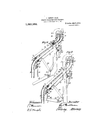
- Figure 1 is a side elevation, partly lin seev tion, illustrating one form of my invention
- Fi 2' is a similar view showing the parts in di erent position
- Fig. 3 is a detail view showing the modeof pivoting the magazines
- Fi 4 and 5 are views similar to Figs. 1 and 2, illustrating a modiicatiom
- Figs. 6 and i are simjlar vlews illustrating another modification
- Figs. 8 and 9 are similar views illustrating still another modification.
- the escapeinenty levers 9, 10 of the magazines are connected with forwardly-projecting pushers 11, '12, each set of which, according to the particular magazine in register with the assembler entrance 8, is brought into operative rela;- tionship with the upper arms of a.set of angle levers 13, upon whose other arms the escapement rods 14 of the keys 15 (Fig. 1) operate.
- the magazine 1 is, at its sides, provided with co-axial'pivot pins 16 fnee to turn in fixed bearingson the' 3, havingonits sides co-axial 'pivot pins 18,
- the magazine 1 is slidable fore-and-aft upon the magazine 2 and the latter is similarly" slidable upon the magazine frame 3.
- the pivot-ed -inagazine frame -3 t is, at its front end, through thrust rods 20, connected with arms 21, fast on a rocking shaft 22, which can be turned by means of a hand lever 23, to adjust the magazines relatively to the fixed assembler entrance.
- the lower magazine 2 is in working position. If it be-desired to bring the upper magazine into working position, as in Fig.
- the lever 23 must be turned in the direction of the arrow shown in Fig. 1, so that the front end of the magazine frame 3, with the magazines thereon, will be moved downward, while the magazines at their rear ends turn about their respective pivots 16 and 18.
- the up er edges of the guide plates 17 and 19 of tie magazine entrances 4 and 5 respectively remain closely beneath the ymatrices hanging ou the distributer bar 6,
- the magazines 1 and 2 which, as in the )receding exam lc, are slidable fore-andatit, are supportedpby the magazine frame 3.
- the magazine entrances 4 and 5 are pivotally attached to the-magazine fraaie 3, the entrance 4 by means of pins 24 on arms 25 fixed to the said magazine frame 3, and the entrance 5 by means of pins 26 fixed directly to the magazine frame 3 itself; by these means the said magazine entrances aie connected with the magazines 1 and 2, so that they participate in the movement of the latter.
- the camsv 30 simultaneously lower the magazine frame13 and push it rearward.
- the lowering movement given to the front ends of'the magazines is larger than the lowering movement given to the rear endsrelatively to the length of the arcual movement, and the lengthwise movement of the magazines corresponds with the versed sine of their arcual movement so that both of the magazines are turned about a shifting axis substantially located beneath the distributer bars and above the upper edges of the guide plates of the magazine entrances.
- FIG. 1 A similar device is shown in Figs. (l and 7.
- the cam 301 does not pilsli the magazines lengthwise, but serves solely to raise and lower them, while an arm-321 rigidly connected with the cam, causes the magazines to slide upward, and leaves them free to slide downward b v gravity.
- the ai'm 321 operates upon lateral projections or studs 33 on the magazine frame 3, and 34 on the upper magazine 1.
- the projection 34 is preferably adjustable on the maoazine 1, and the downward movement of tlie magazines is limited by stops.
- the magazine frame 3 has a lug 35, coperating with a fixed stop 36 on the machine frame, while the upper magazine 1 carries on its lower side, a stop rail 37 coo erating with stops 38 on the upper side of t ie lower magazine 2.
- a cam 30 again serves to raise and lower the magazines at their rear ends.
- the lengthwise sliding movement of the magazines, during the raising and lowering is controlled by stationary guiding surfaces or cams 39 and 40, provided on arms 41 fixed-to the machine frame.
- These surfaces 3D and 40 serve as supports for the sido stops B3 and 34 on the magazine frame 3 and upper magazine 1 respectively, so that during the raisingand lowering of the rear ends of the magazines, the studs 33, 34, slide upon the surfaces 89 and 40.
- the form and arrangement of thesurfaces 30 and 40 are such that durin the raising or lowering of the rear ends ofgthe magazines, the required sliding motion of the magazines also takes place.
- a. typographical composing machine the combination of assembling devices to cooperate with a single magazine at a time, and a plurality of conjointly movable magazines,any selected one of which mayv be brought into operative relation thereto, the said magazines being mounted so as to be capable of pivotal movement about inde pendent axes and movement relative to each other Tvvhile passing into and out of such operative position.
- T. ln a typographical composing machine, the combination of assembling devices to cooperate with a single magazine at a time, and a plurality of conjointly movable magazines, any selected one of which may be brought into operative relation thereto, the said magazines being mounted so as to be capable of pivotal movement about independent axes While passing into and out of such operative position, together with means for imparting such pivotal movements thereto.
Landscapes
- Portable Nailing Machines And Staplers (AREA)
Description
C. MUEHLEISEN.
TYPOGRAPHIGAL COMPOSING rviACHINF` APPLICATION FILED PEB.5,1912.
4 SHEETS-SHEET l.
Patented July 9, 1912 EV1/fw {UZ/0,1
, /f/Zff/wgy C. MUEHLEISBN.
TYPOGRAPHIGAL coMPosmG MAGHINE. APPLICATION FILED PEB.5,192.
1,031,952., Patented July 9,1912.
4 SHEETS-SHEET 2.
C. MUEHLEISBN.
TYPOGRAPHICAL COMPOSING MACHINE APPLICATION FILED film, 1912.
1,031,952. l Patented Ju1y9, 1912 4 SHEETS-SHEET 3.
/fl 0' i#7 j; O O O jg Fig 321 may E 2 y 0l 3 '37 E a9 8 @28 9 36/ 3 l] O 27 6 f j )"0 O O O o J 20 ,7 O 79 fl," c? y ocio C. MUBHLEISEN. TYPOGRAPHICAL coMPosING MACHINE.
APPLICATION YILBD IEB. 5. 1912.
Patented July 9, 1912.
4 SHEETS-SHBET 4.
.st-raras PATENT oi'rriror..4
CABL-HUE'H'LEI8EN, 0F BERLIN, GBRKANY, ASSIGNOR TO MERGENTHALER LINOTYPE "1 COMPANY, A CORIORATION 0F NEW YORK.
` TYPOGBAPHICAL MPOSING-MAOBINE Spectoation of Letters Patent.
Patented July 9,' 1912.
appueaeon med rebmary s, 1912. serial no. 675,52L
Toall whom it may concern:
Be it known that I, CARL MUEnLmsr-m, a citizen lof the United States of America, residing at 23 Chausseestrasse, Berlin, N. 4, in the Empire of Germany, have invented new and useful Improvements in Typographical` Composing-Machines, of which the following is a specification.
The invention relates to a typographical omposing machine having a fixed assembler entrance and a plurality of magazines pivotally arranged relatively to the said entrance, which magazines, by means of magazine entrances movable with them, are in constant relation each with its respective distributor. When changing vmagazines in this kind of composing machine, the magazines must be moved relatively to the fixed lassembler entrance in such a manner that the 'relationship between the said magazinesand the magazine entrances shall not be so disturbed as to interfere with the admission of the matrices into themagazines. The aecuv rate admission of the matrices into one or other of the magazines is secured, when the distance betvve n the matrices hanging on the distributer ar and the partition or guideabout which each magazine, with its magazine ent-rance, is capable of being turned, parallel with, and underneath, the respective distributor bar and in, or nearly in, the horizontal plane containing the upper edges of the guide plates of the magazine entrance. The just mentioned axis of the magazines mayveither be real, that is to say, it
may consist of an actual pivot, or it may be imaginary, by which latter term I mean that the location of the axis is determined by t-he resultant or combined effects of the specific movements hereinafter set forth. In the latter case, the turning of the magazines about the respective axes is effected by 'a lever,
which, by means of a push or thrust rod, di-
rectly moves the front ends of the Amagazines relatively to the assembler entrance, and, by means of a link, partially rotates a cam, which simultaneously raises the rear ends of, and longitudinaly moves the magazines.' i
Figure 1 is a side elevation, partly lin seev tion, illustrating one form of my invention; Fi 2'is a similar view showing the parts in di erent position; Fig. 3 is a detail view showing the modeof pivoting the magazines; Fi 4 and 5 are views similar to Figs. 1 and 2, illustrating a modiicatiom; Figs. 6 and i are simjlar vlews illustrating another modification; and Figs. 8 and 9 are similar views illustrating still another modification.
Four constructional forms of the invention are shown in the drawings: The first eonstructional form is shown in side elevation, partly in vertical section in the two different positions of the magazines in Figs. 1 and 2. Fig. 3 is a front view of part of the arrangement shown in Figs.' 1 and 2. In this constructional form the pivotal axes 1.ol y
of the magazines are real and embodied in sitions of the magazines relatively to the t fixed assembler entrance in side elevation, prtly v-in verticalsection, in F 4 and 5, 6= and 7, and 8 and 9 respectively. In all of the said constructional forms, 1 is the upper magazine, 2, the lower magazi e, and 3, the magazine supporting frame. :and 5- are the magazine entrances movable with the magazines 1 and 2, to cohductthe'matrices from the distributer bars 6, 7, to the magazines. 8 is the fixed assembler entrance or plate, adjacent to whichv the front ends of the magazines are movable.. The escapeinenty levers 9, 10 of the magazines are connected with forwardly-projecting pushers 11, '12, each set of which, according to the particular magazine in register with the assembler entrance 8, is brought into operative rela;- tionship with the upper arms of a.set of angle levers 13, upon whose other arms the escapement rods 14 of the keys 15 (Fig. 1) operate.
In the Vfirst constructional form, illustrated in Figs. 1, 2 and 3, the magazine 1 is, at its sides, provided with co-axial'pivot pins 16 fnee to turn in fixed bearingson the' 3, havingonits sides co-axial 'pivot pins 18,
the axis'of--whichextends beneath the distibuter rail 7 and nearly in the lane'in whichterminate'thesupper ends of tli plates 19 of the magazine-entrance-. The magazine 1 is slidable fore-and-aft upon the magazine 2 and the latter is similarly" slidable upon the magazine frame 3. The pivot-ed -inagazine frame -3 tis, at its front end, through thrust rods 20, connected with arms 21, fast on a rocking shaft 22, which can be turned by means of a hand lever 23, to adjust the magazines relatively to the fixed assembler entrance. In Fig. 1, the lower magazine 2 is in working position. If it be-desired to bring the upper magazine into working position, as in Fig. 2, the lever 23 must be turned in the direction of the arrow shown in Fig. 1, so that the front end of the magazine frame 3, with the magazines thereon, will be moved downward, while the magazines at their rear ends turn about their respective pivots 16 and 18. By reason of their special arrangement accor".ing to the present' invention, the up er edges of the guide plates 17 and 19 of tie magazine entrances 4 and 5 respectively, remain closely beneath the ymatrices hanging ou the distributer bar 6,
7, so that, even in this position of the magazines, the matrices can freely enter between the guide plates 17, 19.
In the second constructional form shown in Figs. 4 and 5, the magazines 1 and 2 which, as in the )receding exam lc, are slidable fore-andatit, are supportedpby the magazine frame 3. The magazine entrances 4 and 5 are pivotally attached to the-magazine fraaie 3, the entrance 4 by means of pins 24 on arms 25 fixed to the said magazine frame 3, and the entrance 5 by means of pins 26 fixed directly to the magazine frame 3 itself; by these means the said magazine entrances aie connected with the magazines 1 and 2, so that they participate in the movement of the latter. Itwill )e seen that when the magazines 1 and 2 are shifted relatively in the manner subsepiently to be described, the throats 4 and 6 t ne to their contact with the magazines, will be shifted about their pivots 24 and 2G, respectively, but not to an extent suflieient to afl'ect their constant relationship to the distributor rails 6 and 7. The front end of the magazine frame 3 as in the preceding example, is connected by means of thrust rods 20 to arms 21 on the rocking shaft 22 which can be turned by a hand lever 23. The arms 21 are also connected by means of links 27 with arms 28 fast to a shaft 29 carrying cams 30 and citpable of turning in bearings in the main rame. The cams 30 -act on the underside of the magazine frame and on lu s 31 extending downward from the under side ot the-magazine frame 8.-. When the lever 28 -ia raised fromthe e guidey position in lwhich it is shown in- Fig.4, to
that-inwhich it is shown in Fig. 5, the camsv 30 simultaneously lower the magazine frame13 and push it rearward. By these means the lowering movement given to the front ends of'the magazines is larger than the lowering movement given to the rear endsrelatively to the length of the arcual movement, and the lengthwise movement of the magazines corresponds with the versed sine of their arcual movement so that both of the magazines are turned about a shifting axis substantially located beneath the distributer bars and above the upper edges of the guide plates of the magazine entrances.
A similar device is shown in Figs. (l and 7. In this construction the cam 301 does not pilsli the magazines lengthwise, but serves solely to raise and lower them, while an arm-321 rigidly connected with the cam, causes the magazines to slide upward, and leaves them free to slide downward b v gravity. The ai'm 321 operates upon lateral projections or studs 33 on the magazine frame 3, and 34 on the upper magazine 1. The projection 34 is preferably adjustable on the maoazine 1, and the downward movement of tlie magazines is limited by stops. To this end the magazine frame 3 has a lug 35, coperating with a fixed stop 36 on the machine frame, while the upper magazine 1 carries on its lower side, a stop rail 37 coo erating with stops 38 on the upper side of t ie lower magazine 2.
In the constructional forms shown in Figs. 8 and 9, a cam 30 again serves to raise and lower the magazines at their rear ends. The lengthwise sliding movement of the magazines, during the raising and lowering is controlled by stationary guiding surfaces or cams 39 and 40, provided on arms 41 fixed-to the machine frame. These surfaces 3D and 40 serve as supports for the sido stops B3 and 34 on the magazine frame 3 and upper magazine 1 respectively, so that during the raisingand lowering of the rear ends of the magazines, the studs 33, 34, slide upon the surfaces 89 and 40. The form and arrangement of thesurfaces 30 and 40 are such that durin the raising or lowering of the rear ends ofgthe magazines, the required sliding motion of the magazines also takes place.
Having described my invention, I declare that what I claim and desire to secure by Letters-Patent is 1. In a typographical composing machine, the combination of assembling devices to cooperatewith a, single magazineat a time, and a plurality of conjointly movable magazines, any selected one of which may be broughtl into operative relation thereto, the said magazines being mounted so as to be capable of movement-with reference to each other in passing into and out of such operative position.
2. In a typographicai composing machine', the combination of assembling devices to cooperatel with'a single magazine at a time. and a plurality of conjointly movable magazines, any selected one of which may be brought into operativo relation thereto, the said magazines being mounted so as to be capable of movement with reference to each other in passing into and out ot such operative position, together with means for imparting such relative movements thereto.
3.`In a typographical composing machine, the Vcombination of assembling devices to cooperate with a single magazine at a time, and"a"plui'ality of conjointly and pivotally movable magazines, any selected one of which may be brought into operative relation thereto, the said magazines being mounted so as to bc capable of movenient With reference to each other during their pivotal movenwnt in passing into and out of such operative position.
4. ln a typographical composing machine, the combination ot assembling devices to cooperate with a single magazine at a time, and a plurality otl conjointly and pivotally movable magazines, any selected one of which may be brought into operative relation thereto, the said 4magazines being mounted so as to be capable of movement with reference to each other during their pivotal movement in passing into and out of such operative position. together with means for imparting such pivotal and relativo movements thereto.
cpabe of pivotal movement about independent axes while passing into and out of such operative position.
6. In a. typographical composing machine, the combination of assembling devices to cooperate with a single magazine at a time, and a plurality of conjointly movable magazines,any selected one of which mayv be brought into operative relation thereto, the said magazines being mounted so as to be capable of pivotal movement about inde pendent axes and movement relative to each other Tvvhile passing into and out of such operative position.
T. ln a typographical composing machine, the combination of assembling devices to cooperate with a single magazine at a time, and a plurality of conjointly movable magazines, any selected one of which may be brought into operative relation thereto, the said magazines being mounted so as to be capable of pivotal movement about independent axes While passing into and out of such operative position, together with means for imparting such pivotal movements thereto.
S. In a typographical composing machine, the combination ofassembling devices to cooperate with a single magazine at a time, and a plurality of conjointly movable magazines, any selected one of which may be brought into operative lrelation thereto, the saidl magazines being mounted so as to be. capable of pivotal movement about independent axes and movement relative to each other while passing int'o and out of such operative position, together with means for imparting such pivotal and relative movements thereto4 In Witness whereof I have hereunto set my hand in thepresence of two witnesses.
CARL MU EHLEISEN.
Witnesses `VVOLDEMAR HAUPT, HENRY Haaren.
Priority Applications (1)
| Application Number | Priority Date | Filing Date | Title |
|---|---|---|---|
| US67552412A US1031952A (en) | 1912-02-05 | 1912-02-05 | Typographical composing-machine. |
Applications Claiming Priority (1)
| Application Number | Priority Date | Filing Date | Title |
|---|---|---|---|
| US67552412A US1031952A (en) | 1912-02-05 | 1912-02-05 | Typographical composing-machine. |
Publications (1)
| Publication Number | Publication Date |
|---|---|
| US1031952A true US1031952A (en) | 1912-07-09 |
Family
ID=3100243
Family Applications (1)
| Application Number | Title | Priority Date | Filing Date |
|---|---|---|---|
| US67552412A Expired - Lifetime US1031952A (en) | 1912-02-05 | 1912-02-05 | Typographical composing-machine. |
Country Status (1)
| Country | Link |
|---|---|
| US (1) | US1031952A (en) |
-
1912
- 1912-02-05 US US67552412A patent/US1031952A/en not_active Expired - Lifetime
Similar Documents
| Publication | Publication Date | Title |
|---|---|---|
| US1136553A (en) | Typographical composing-machine. | |
| US1681671A (en) | Typographical machine | |
| US859170A (en) | Linotype-machine. | |
| US1138003A (en) | Typographical machine. | |
| US1116620A (en) | Typographical composing-machine. | |
| US859647A (en) | Linotype-machine. | |
| US2155588A (en) | Typographical composing and distributing machine | |
| US1088442A (en) | Typographical composing-machine. | |
| US1237043A (en) | Typographical machine. | |
| US1525509A (en) | Typographical composing machine | |
| US1125150A (en) | Typographical composing-machine. | |
| US1955618A (en) | Typographical composing and distributing machine | |
| US1212542A (en) | Typographical composing-machine. | |
| US2689038A (en) | Typographical composing machine | |
| US1427511A (en) | Distributing mechanism of typographical composing and casting machines | |
| US797413A (en) | Linotype-machine. | |
| US789646A (en) | Typographic machine. | |
| US1304708A (en) | Typographical machine | |
| US2079199A (en) | Typographical machine | |
| US2068288A (en) | Assembling mechanism of typographical composing machines | |
| US1161161A (en) | Typographical composing-machine. | |
| US1135400A (en) | Typographical composing-machine. | |
| US921065A (en) | Matrix-distributing mechanism. | |
| US1270328A (en) | Typographical machine. | |
| US1225633A (en) | Typographical machine. |