US10314396B2 - Quick detachable slide rail and drawer mounting structure - Google Patents
Quick detachable slide rail and drawer mounting structure Download PDFInfo
- Publication number
- US10314396B2 US10314396B2 US15/717,815 US201715717815A US10314396B2 US 10314396 B2 US10314396 B2 US 10314396B2 US 201715717815 A US201715717815 A US 201715717815A US 10314396 B2 US10314396 B2 US 10314396B2
- Authority
- US
- United States
- Prior art keywords
- slide rail
- drawer
- bottom panel
- device set
- connection device
- Prior art date
- Legal status (The legal status is an assumption and is not a legal conclusion. Google has not performed a legal analysis and makes no representation as to the accuracy of the status listed.)
- Active
Links
- 230000013011 mating Effects 0.000 claims abstract description 37
- 230000035939 shock Effects 0.000 claims description 19
- 238000006073 displacement reaction Methods 0.000 claims description 18
- 230000004308 accommodation Effects 0.000 claims description 14
- 238000003780 insertion Methods 0.000 claims description 6
- 230000037431 insertion Effects 0.000 claims description 6
- 238000013016 damping Methods 0.000 claims description 5
- 238000009434 installation Methods 0.000 description 2
- 238000004891 communication Methods 0.000 description 1
- 238000005516 engineering process Methods 0.000 description 1
Images


Classifications
-
- A—HUMAN NECESSITIES
- A47—FURNITURE; DOMESTIC ARTICLES OR APPLIANCES; COFFEE MILLS; SPICE MILLS; SUCTION CLEANERS IN GENERAL
- A47B—TABLES; DESKS; OFFICE FURNITURE; CABINETS; DRAWERS; GENERAL DETAILS OF FURNITURE
- A47B88/00—Drawers for tables, cabinets or like furniture; Guides for drawers
- A47B88/40—Sliding drawers; Slides or guides therefor
- A47B88/423—Fastening devices for slides or guides
- A47B88/427—Fastening devices for slides or guides at drawer side
-
- A—HUMAN NECESSITIES
- A47—FURNITURE; DOMESTIC ARTICLES OR APPLIANCES; COFFEE MILLS; SPICE MILLS; SUCTION CLEANERS IN GENERAL
- A47B—TABLES; DESKS; OFFICE FURNITURE; CABINETS; DRAWERS; GENERAL DETAILS OF FURNITURE
- A47B88/00—Drawers for tables, cabinets or like furniture; Guides for drawers
- A47B88/40—Sliding drawers; Slides or guides therefor
- A47B88/407—Adjustably or detachably mounted drawers
-
- A—HUMAN NECESSITIES
- A47—FURNITURE; DOMESTIC ARTICLES OR APPLIANCES; COFFEE MILLS; SPICE MILLS; SUCTION CLEANERS IN GENERAL
- A47B—TABLES; DESKS; OFFICE FURNITURE; CABINETS; DRAWERS; GENERAL DETAILS OF FURNITURE
- A47B88/00—Drawers for tables, cabinets or like furniture; Guides for drawers
- A47B88/40—Sliding drawers; Slides or guides therefor
- A47B88/423—Fastening devices for slides or guides
-
- A—HUMAN NECESSITIES
- A47—FURNITURE; DOMESTIC ARTICLES OR APPLIANCES; COFFEE MILLS; SPICE MILLS; SUCTION CLEANERS IN GENERAL
- A47B—TABLES; DESKS; OFFICE FURNITURE; CABINETS; DRAWERS; GENERAL DETAILS OF FURNITURE
- A47B88/00—Drawers for tables, cabinets or like furniture; Guides for drawers
- A47B88/40—Sliding drawers; Slides or guides therefor
- A47B88/473—Braking devices, e.g. linear or rotational dampers or friction brakes; Buffers; End stops
- A47B88/477—Buffers; End stops
-
- A—HUMAN NECESSITIES
- A47—FURNITURE; DOMESTIC ARTICLES OR APPLIANCES; COFFEE MILLS; SPICE MILLS; SUCTION CLEANERS IN GENERAL
- A47B—TABLES; DESKS; OFFICE FURNITURE; CABINETS; DRAWERS; GENERAL DETAILS OF FURNITURE
- A47B88/00—Drawers for tables, cabinets or like furniture; Guides for drawers
- A47B88/40—Sliding drawers; Slides or guides therefor
- A47B88/497—Sliding drawers; Slides or guides therefor with other guiding mechanisms, e.g. scissor mechanisms
-
- A—HUMAN NECESSITIES
- A47—FURNITURE; DOMESTIC ARTICLES OR APPLIANCES; COFFEE MILLS; SPICE MILLS; SUCTION CLEANERS IN GENERAL
- A47B—TABLES; DESKS; OFFICE FURNITURE; CABINETS; DRAWERS; GENERAL DETAILS OF FURNITURE
- A47B88/00—Drawers for tables, cabinets or like furniture; Guides for drawers
- A47B88/40—Sliding drawers; Slides or guides therefor
- A47B88/423—Fastening devices for slides or guides
- A47B2088/4235—Fastening devices for slides or guides having a latch mechanism coupling or disconnecting a drawer with drawer side slide from the rest of the slide members
-
- A—HUMAN NECESSITIES
- A47—FURNITURE; DOMESTIC ARTICLES OR APPLIANCES; COFFEE MILLS; SPICE MILLS; SUCTION CLEANERS IN GENERAL
- A47B—TABLES; DESKS; OFFICE FURNITURE; CABINETS; DRAWERS; GENERAL DETAILS OF FURNITURE
- A47B88/00—Drawers for tables, cabinets or like furniture; Guides for drawers
- A47B88/40—Sliding drawers; Slides or guides therefor
- A47B88/423—Fastening devices for slides or guides
- A47B88/427—Fastening devices for slides or guides at drawer side
- A47B2088/4274—Fastening devices for slides or guides at drawer side the drawer being detachable as a whole from a slide frame
-
- A—HUMAN NECESSITIES
- A47—FURNITURE; DOMESTIC ARTICLES OR APPLIANCES; COFFEE MILLS; SPICE MILLS; SUCTION CLEANERS IN GENERAL
- A47B—TABLES; DESKS; OFFICE FURNITURE; CABINETS; DRAWERS; GENERAL DETAILS OF FURNITURE
- A47B88/00—Drawers for tables, cabinets or like furniture; Guides for drawers
- A47B88/40—Sliding drawers; Slides or guides therefor
- A47B88/423—Fastening devices for slides or guides
- A47B88/427—Fastening devices for slides or guides at drawer side
- A47B2088/4276—Fastening devices for slides or guides at drawer side at drawer front via latch means or locking lever
Definitions
- the present invention relates to sliding rail technology and more particularly to a quick detachable slide rail and drawer mounting structure for quick connection between a slide rail assembly and a drawer in a detachable manner, prohibiting relative displacement between the drawer and the slide rail assembly.
- connection structure For connection between a drawer and a slide rail assembly in a cabinet, a connection structure is necessary. When connected, the drawer can be moved with the slide rail assembly in and out of the cabinet.
- This connection structure has a connection member fastened to a distal end of the slide rail assembly, and a mating connection device affixed to the bottom panel of the drawer and fastened to the connection member.
- the present invention has been accomplished under the circumstances in view. It is therefore the main object of the present invention to provide a quick detachable slide rail and drawer mounting structure, which uses a connection member and a mating connection device set for connection to the slide rail assembly and the drawer respectively, allowing the drawer and the slide rail assembly to be conveniently and detachably fastened together without any tools.
- a quick detachable slide rail and drawer mounting structure comprises a slide rail assembly, a drawer, a connection member and a mating connection device set.
- the slide rail assembly comprises an inner slide rail and outer slide rail.
- the outer slide rail is attached onto the inner slide rail and slidable relative to the inner slide rail.
- the drawer is fastened to the outer slide rail of the slide rail assembly.
- the connection member comprises a base, and a first toothed rack disposed at one lateral side of the base.
- the base is affixed to a distal end of the outer slide rail of the slide rail assembly to hold the first toothed rack at one lateral side of the outer slide rail.
- the mating connection device set comprises a holder block and an abutment member.
- the holder block comprises a bottom panel, and a second toothed rack disposed at one side of the bottom panel.
- the abutment member is mounted at a bottom side of the bottom panel and movable in and out of the bottom panel.
- the holder block is mounted at a bottom wall of the drawer.
- the first toothed rack of the connection member is engaged with the second toothed rack of the mating connection device set to prohibit the drawer from longitudinal and sideway displacement, and the abutment member of the mating connection device set is exposed to the outside of the bottom panel and disposed at a bottom side of the base of the connection member to prohibit relative vertical displacement between the drawer and the outer slide rail.
- FIG. 1 is an oblique elevational view illustrating a connection member of a quick detachable slide rail and drawer mounting structure mounted at a slide rail assembly in accordance with the present invention.
- FIG. 2 is an oblique elevational view of the mating connection device set of the quick detachable slide rail and drawer mounting structure in accordance with the present invention.
- FIG. 3 corresponds to FIG. 2 when viewed from another angle.
- FIG. 4 is an exploded view of the mating connection device set of the quick detachable slide rail and drawer mounting structure in accordance with the present invention.
- FIG. 5 is another exploded view of the mating connection device set of the quick detachable slide rail and drawer mounting structure in accordance with the present invention.
- FIG. 6 is a schematic sectional view of the mating connection device set of the quick detachable slide rail and drawer mounting structure in accordance with the present invention.
- FIG. 7 is a schematic drawing of the present invention, illustrating the position of the shock damper of the mating connection device set adjusted.
- FIG. 8 is a schematic installed view of the present invention, illustrating the connection relationship between the mating connection device set and the drawer.
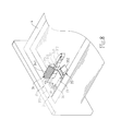
- FIG. 9 is a schematic bottom view of the present invention, illustrating connection between the slide rail assembly and the drawer.
- FIG. 10 is a schematic side view of the present invention, illustrating the connection relationship between the slide rail assembly and the drawer.
- the quick detachable slide rail and drawer mounting structure comprises a slide rail assembly 1 , a connection member 2 , a mating connection device set 3 and a drawer 4 .
- the slide rail assembly 1 comprises an inner slide rail 11 and an outer slide rail 12 .
- the outer slide rail 12 is attached onto the inner slide rail 11 and slidable relative to the inner slide rail 11 .
- the connection member 2 comprises a base 21 , a first toothed rack 22 disposed at one lateral side relative to the base 21 , a stop block 23 extended from the base 21 , and an insertion groove 24 defined between the stop block 23 and the first toothed rack 22 .
- the base 21 is affixed to a free end of the outer slide rail 12 of the slide rail assembly 1 to hold the first toothed rack 22 at one lateral side of the outer slide rail 12 .
- the mating connection device set 3 comprises a holder block 31 , an abutment member 32 , a spring member 33 , a push member 34 , a shock damper 35 , an adjustment screw bolt 36 and a top cover 37 .
- the holder block 31 of the mating connection device set 3 comprises a bottom panel 311 , a mounting plate 317 extended from one end of the bottom panel 311 , a second toothed rack 312 extended from one lateral side of the bottom panel 311 remote from the mounting plate 317 , a receptacle 313 located a bottom side of the bottom panel 311 and defining therein an accommodation chamber 314 and a front opening 315 in communication between the accommodation chamber 314 and the outside of the receptacle 313 .
- the abutment member 32 has two opposite ends thereof respectively terminating in an abutment end portion 321 and a mounting end portion 322 with two opposing locating grooves 323 .
- the abutment member 32 is mounted in the accommodation chamber 314 with the abutment end portion 321 extended out of the front opening 315 of the receptacle 313 .
- the spring member 33 is stopped between the mounting end portion 322 of the abutment member 32 and an inside wall of the accommodation chamber 314 .
- the push member 34 attached to the outer surface of the receptacle 313 , comprising a pushing portion 341 and a retaining portion 342 located at a bottom side of the pushing portion 341 and engaged with the locating grooves 323 of the abutment member 32 in the accommodation chamber 314 .
- the push member 34 can move the abutment member 32 toward the inside of the accommodation chamber 314 to compress the spring member 33 for storing elastic restoring energy.
- the bottom panel 311 of the mating connection device set 3 further defines a guide groove 316 .
- the shock damper 35 comprises a displacement portion 351 , a beveled shock damping portion 352 located at a front end of the displacement portion 351 , and a fixed nut 353 located at one lateral side thereof.
- the displacement portion 351 of the shock damper 35 is supported on a top surface of the bottom panel 311 .
- the fixed nut 353 is positioned in the guide groove 316 .
- the adjustment screw bolt 36 is threaded into the fixed nut 353 .
- the top cover 37 is covered on the top surface of the bottom panel 311 to hold the shock damper 35 and the adjustment screw bolt 36 therein.
- the adjustment screw bolt 36 can be rotated to move the displacement portion 351 of the shock damper 35 along the surface of the bottom panel 311 , thereby moving the shock damping portion 352 in or out of the bottom panel 311 .
- the mounting plate 317 of the mating connection device set 3 is affixed to a bottom wall of the drawer 4 , and then the drawer 4 is fastened to the outer slide rail 12 , and then the connection member 2 and the mating connection device set 3 are moved toward each other to force the first toothed rack 22 of the connection member 2 into engagement with the second toothed rack 312 of the mating connection device set 3 , securing the drawer 4 positively in place against longitudinal and sideway displacement.
- the abutment member 32 of the mating connection device set 3 is exposed to the outside of the bottom panel 311 and positioned in the insertion groove 24 of the connection member 2 to prohibit relative vertical displacement between the drawer 4 and the outer slide rail 12 .
- the adjustment screw bolt 36 can be rotated to move the shock damping portion 352 of the shock damper 35 out of the bottom panel 311 into engagement in between the drawer 4 and the base 21 of the connection member 2 , adjusting the elevation of the drawer 4 and eliminating the gap between the drawer 4 and the base 21 to reduce shocks.
Landscapes
- Drawers Of Furniture (AREA)
Abstract
Description
Claims (8)
Priority Applications (1)
| Application Number | Priority Date | Filing Date | Title |
|---|---|---|---|
| US15/717,815 US10314396B2 (en) | 2017-09-27 | 2017-09-27 | Quick detachable slide rail and drawer mounting structure |
Applications Claiming Priority (1)
| Application Number | Priority Date | Filing Date | Title |
|---|---|---|---|
| US15/717,815 US10314396B2 (en) | 2017-09-27 | 2017-09-27 | Quick detachable slide rail and drawer mounting structure |
Publications (2)
| Publication Number | Publication Date |
|---|---|
| US20190090633A1 US20190090633A1 (en) | 2019-03-28 |
| US10314396B2 true US10314396B2 (en) | 2019-06-11 |
Family
ID=65806920
Family Applications (1)
| Application Number | Title | Priority Date | Filing Date |
|---|---|---|---|
| US15/717,815 Active US10314396B2 (en) | 2017-09-27 | 2017-09-27 | Quick detachable slide rail and drawer mounting structure |
Country Status (1)
| Country | Link |
|---|---|
| US (1) | US10314396B2 (en) |
Cited By (3)
| Publication number | Priority date | Publication date | Assignee | Title |
|---|---|---|---|---|
| US20190166996A1 (en) * | 2017-12-04 | 2019-06-06 | Grass Gmbh | Device for connecting a push element to a guide rail, guidance system and piece of furniture or household appliance |
| US10799020B1 (en) * | 2019-05-24 | 2020-10-13 | Rev-A-Shelf Company, Llc | Multi-level cabinet storage system |
| US11039687B1 (en) * | 2020-01-13 | 2021-06-22 | Hardware Resources, Inc. | Undermount drawer slide position adjustment apparatus and method of use |
Families Citing this family (5)
| Publication number | Priority date | Publication date | Assignee | Title |
|---|---|---|---|---|
| TWI694791B (en) * | 2018-02-27 | 2020-06-01 | 川湖科技股份有限公司 | Slide rail assembly for furniture |
| CN109512174A (en) * | 2018-12-30 | 2019-03-26 | 广东合固五金精密制造有限公司 | A kind of preceding attachment device of drawer sliding rail modularization adjusting |
| CN110754821B (en) * | 2019-12-11 | 2024-09-13 | 苏州升德精密电气有限公司 | Drawer slide rail type quick-release device |
| CN115670146B (en) * | 2022-11-11 | 2025-12-09 | 广东东泰五金精密制造有限公司 | Drawer slide rail assembly of integrated optimization adjusting structure |
| USD1053697S1 (en) * | 2023-04-13 | 2024-12-10 | Nan Juen International Co., Ltd. | Slide rail fastener |
Citations (6)
| Publication number | Priority date | Publication date | Assignee | Title |
|---|---|---|---|---|
| US7549712B2 (en) * | 2003-05-13 | 2009-06-23 | Grass America, Inc. | Front locking device for releasably engaging a drawer to a drawer slide |
| CN202681151U (en) * | 2012-05-14 | 2013-01-23 | 东莞市博锐特五金塑胶制品有限公司 | Adjuster for drawer slide rail |
| US8979223B2 (en) * | 2012-12-12 | 2015-03-17 | Nan Juen International Co., Ltd. | Adjustable coupling device for connection between sliding rail assembly and a sliding box |
| US9060604B2 (en) * | 2011-09-08 | 2015-06-23 | Arturo Salice S.P.A. | Device and method for laterally centring a drawer or the like on a pull-out guide and a hooking device provided with the device |
| US20160242543A1 (en) * | 2015-02-25 | 2016-08-25 | Grass Gmbh | Device for the Detachable Connection of a Furniture Pull-Out Movably Guided in a Furniture Body via a Guide Unit with the Guide Unit |
| US20170135476A1 (en) * | 2015-11-12 | 2017-05-18 | King Slide Works Co., Ltd. | Quick-release mechanism for drawer slide parts |
-
2017
- 2017-09-27 US US15/717,815 patent/US10314396B2/en active Active
Patent Citations (6)
| Publication number | Priority date | Publication date | Assignee | Title |
|---|---|---|---|---|
| US7549712B2 (en) * | 2003-05-13 | 2009-06-23 | Grass America, Inc. | Front locking device for releasably engaging a drawer to a drawer slide |
| US9060604B2 (en) * | 2011-09-08 | 2015-06-23 | Arturo Salice S.P.A. | Device and method for laterally centring a drawer or the like on a pull-out guide and a hooking device provided with the device |
| CN202681151U (en) * | 2012-05-14 | 2013-01-23 | 东莞市博锐特五金塑胶制品有限公司 | Adjuster for drawer slide rail |
| US8979223B2 (en) * | 2012-12-12 | 2015-03-17 | Nan Juen International Co., Ltd. | Adjustable coupling device for connection between sliding rail assembly and a sliding box |
| US20160242543A1 (en) * | 2015-02-25 | 2016-08-25 | Grass Gmbh | Device for the Detachable Connection of a Furniture Pull-Out Movably Guided in a Furniture Body via a Guide Unit with the Guide Unit |
| US20170135476A1 (en) * | 2015-11-12 | 2017-05-18 | King Slide Works Co., Ltd. | Quick-release mechanism for drawer slide parts |
Cited By (6)
| Publication number | Priority date | Publication date | Assignee | Title |
|---|---|---|---|---|
| US20190166996A1 (en) * | 2017-12-04 | 2019-06-06 | Grass Gmbh | Device for connecting a push element to a guide rail, guidance system and piece of furniture or household appliance |
| US10945523B2 (en) * | 2017-12-04 | 2021-03-16 | Grass Gmbh | Device for connecting a push element to a guide rail, guidance system and piece of furniture or household appliance |
| US10799020B1 (en) * | 2019-05-24 | 2020-10-13 | Rev-A-Shelf Company, Llc | Multi-level cabinet storage system |
| US11659924B2 (en) | 2019-05-24 | 2023-05-30 | Rev-A-Shelf Company, Llc | Multi-level cabinet storage system |
| US11039687B1 (en) * | 2020-01-13 | 2021-06-22 | Hardware Resources, Inc. | Undermount drawer slide position adjustment apparatus and method of use |
| US11540629B2 (en) | 2020-01-13 | 2023-01-03 | Hardware Resources, Inc. | Undermount drawer slide position adjustment apparatus and method of use |
Also Published As
| Publication number | Publication date |
|---|---|
| US20190090633A1 (en) | 2019-03-28 |
Similar Documents
| Publication | Publication Date | Title |
|---|---|---|
| US10314396B2 (en) | Quick detachable slide rail and drawer mounting structure | |
| CN105899105B (en) | Drawer pull-out guide | |
| US10436549B1 (en) | Rifle handguard system | |
| US9480183B2 (en) | Slide rail assembly | |
| US8650711B1 (en) | Hinge assembly with damping device | |
| US8979223B2 (en) | Adjustable coupling device for connection between sliding rail assembly and a sliding box | |
| EP3462075B1 (en) | A connecting device and a gimbal apparatus | |
| US6678988B1 (en) | Recoil dampening device for gun sight | |
| RU2006102426A (en) | ADJUSTABLE BACKREST OF THE BUTT FOR THE RUNNING WEAPON | |
| US9675175B1 (en) | Slide rail assembly | |
| CN102159117A (en) | Moveable drawer with railing adjustment | |
| JP6490089B2 (en) | Fitting for sliding door | |
| WO2011152109A1 (en) | Stage mechanism | |
| US11898597B2 (en) | Flap bearing having an adjustment aid | |
| US9936809B2 (en) | Cabinet assembly having a releasable support foot | |
| MY196234A (en) | Document Cover Closer and Office Equipment Having The Same | |
| US8707610B2 (en) | Scope mounting apparatus for firearm | |
| US10437138B1 (en) | Camera L-plate | |
| US7111360B1 (en) | Door catch | |
| CN213393002U (en) | Display screen unit and splicing type display screen | |
| RU2014153493A (en) | LOCKING AND DAMPING DEVICE FOR SLIDING DOOR CARRIAGE ASSEMBLIES FOR BUILDINGS OR FURNITURE AND SIMILAR THESE | |
| US20110303206A1 (en) | Magazine | |
| MY207265A (en) | Arrangement for guiding a movable furniture part | |
| CN104633607B (en) | Torch and its fixed structure | |
| US20230059249A1 (en) | Pull-out guide for a movable furniture part |
Legal Events
| Date | Code | Title | Description |
|---|---|---|---|
| AS | Assignment |
Owner name: NAN JUEN INTERNATIONAL CO., LTD., TAIWAN Free format text: ASSIGNMENT OF ASSIGNORS INTEREST;ASSIGNORS:HSU, CHENG-LIANG;LIAO, WEI-LIANG;REEL/FRAME:043719/0915 Effective date: 20170921 |
|
| FEPP | Fee payment procedure |
Free format text: ENTITY STATUS SET TO UNDISCOUNTED (ORIGINAL EVENT CODE: BIG.); ENTITY STATUS OF PATENT OWNER: LARGE ENTITY |
|
| STPP | Information on status: patent application and granting procedure in general |
Free format text: NOTICE OF ALLOWANCE MAILED -- APPLICATION RECEIVED IN OFFICE OF PUBLICATIONS |
|
| STCF | Information on status: patent grant |
Free format text: PATENTED CASE |
|
| MAFP | Maintenance fee payment |
Free format text: PAYMENT OF MAINTENANCE FEE, 4TH YEAR, LARGE ENTITY (ORIGINAL EVENT CODE: M1551); ENTITY STATUS OF PATENT OWNER: LARGE ENTITY Year of fee payment: 4 |