US10312670B2 - Drive device for vacuum circuit breaker chassis - Google Patents
Drive device for vacuum circuit breaker chassis Download PDFInfo
- Publication number
- US10312670B2 US10312670B2 US15/656,833 US201715656833A US10312670B2 US 10312670 B2 US10312670 B2 US 10312670B2 US 201715656833 A US201715656833 A US 201715656833A US 10312670 B2 US10312670 B2 US 10312670B2
- Authority
- US
- United States
- Prior art keywords
- drive
- chain wheel
- chassis
- circuit breaker
- drive motor
- Prior art date
- Legal status (The legal status is an assumption and is not a legal conclusion. Google has not performed a legal analysis and makes no representation as to the accuracy of the status listed.)
- Active
Links
Images


Classifications
-
- H—ELECTRICITY
- H02—GENERATION; CONVERSION OR DISTRIBUTION OF ELECTRIC POWER
- H02B—BOARDS, SUBSTATIONS OR SWITCHING ARRANGEMENTS FOR THE SUPPLY OR DISTRIBUTION OF ELECTRIC POWER
- H02B11/00—Switchgear having carriage withdrawable for isolation
- H02B11/12—Switchgear having carriage withdrawable for isolation with isolation by horizontal withdrawal
- H02B11/127—Withdrawal mechanism
- H02B11/133—Withdrawal mechanism with interlock
-
- F—MECHANICAL ENGINEERING; LIGHTING; HEATING; WEAPONS; BLASTING
- F16—ENGINEERING ELEMENTS AND UNITS; GENERAL MEASURES FOR PRODUCING AND MAINTAINING EFFECTIVE FUNCTIONING OF MACHINES OR INSTALLATIONS; THERMAL INSULATION IN GENERAL
- F16H—GEARING
- F16H25/00—Gearings comprising primarily only cams, cam-followers and screw-and-nut mechanisms
- F16H25/18—Gearings comprising primarily only cams, cam-followers and screw-and-nut mechanisms for conveying or interconverting oscillating or reciprocating motions
- F16H25/20—Screw mechanisms
- F16H25/24—Elements essential to such mechanisms, e.g. screws, nuts
- F16H25/2454—Brakes; Rotational locks
-
- H—ELECTRICITY
- H01—ELECTRIC ELEMENTS
- H01H—ELECTRIC SWITCHES; RELAYS; SELECTORS; EMERGENCY PROTECTIVE DEVICES
- H01H33/00—High-tension or heavy-current switches with arc-extinguishing or arc-preventing means
- H01H33/60—Switches wherein the means for extinguishing or preventing the arc do not include separate means for obtaining or increasing flow of arc-extinguishing fluid
- H01H33/66—Vacuum switches
- H01H33/666—Operating arrangements
-
- H—ELECTRICITY
- H02—GENERATION; CONVERSION OR DISTRIBUTION OF ELECTRIC POWER
- H02B—BOARDS, SUBSTATIONS OR SWITCHING ARRANGEMENTS FOR THE SUPPLY OR DISTRIBUTION OF ELECTRIC POWER
- H02B11/00—Switchgear having carriage withdrawable for isolation
- H02B11/12—Switchgear having carriage withdrawable for isolation with isolation by horizontal withdrawal
- H02B11/127—Withdrawal mechanism
-
- H—ELECTRICITY
- H02—GENERATION; CONVERSION OR DISTRIBUTION OF ELECTRIC POWER
- H02K—DYNAMO-ELECTRIC MACHINES
- H02K7/00—Arrangements for handling mechanical energy structurally associated with dynamo-electric machines, e.g. structural association with mechanical driving motors or auxiliary dynamo-electric machines
- H02K7/06—Means for converting reciprocating motion into rotary motion or vice versa
-
- H—ELECTRICITY
- H02—GENERATION; CONVERSION OR DISTRIBUTION OF ELECTRIC POWER
- H02K—DYNAMO-ELECTRIC MACHINES
- H02K7/00—Arrangements for handling mechanical energy structurally associated with dynamo-electric machines, e.g. structural association with mechanical driving motors or auxiliary dynamo-electric machines
- H02K7/10—Structural association with clutches, brakes, gears, pulleys or mechanical starters
- H02K7/108—Structural association with clutches, brakes, gears, pulleys or mechanical starters with friction clutches
-
- H—ELECTRICITY
- H02—GENERATION; CONVERSION OR DISTRIBUTION OF ELECTRIC POWER
- H02K—DYNAMO-ELECTRIC MACHINES
- H02K7/00—Arrangements for handling mechanical energy structurally associated with dynamo-electric machines, e.g. structural association with mechanical driving motors or auxiliary dynamo-electric machines
- H02K7/10—Structural association with clutches, brakes, gears, pulleys or mechanical starters
- H02K7/116—Structural association with clutches, brakes, gears, pulleys or mechanical starters with gears
-
- F—MECHANICAL ENGINEERING; LIGHTING; HEATING; WEAPONS; BLASTING
- F16—ENGINEERING ELEMENTS AND UNITS; GENERAL MEASURES FOR PRODUCING AND MAINTAINING EFFECTIVE FUNCTIONING OF MACHINES OR INSTALLATIONS; THERMAL INSULATION IN GENERAL
- F16H—GEARING
- F16H25/00—Gearings comprising primarily only cams, cam-followers and screw-and-nut mechanisms
- F16H25/18—Gearings comprising primarily only cams, cam-followers and screw-and-nut mechanisms for conveying or interconverting oscillating or reciprocating motions
- F16H25/20—Screw mechanisms
- F16H2025/2031—Actuator casings
-
- F—MECHANICAL ENGINEERING; LIGHTING; HEATING; WEAPONS; BLASTING
- F16—ENGINEERING ELEMENTS AND UNITS; GENERAL MEASURES FOR PRODUCING AND MAINTAINING EFFECTIVE FUNCTIONING OF MACHINES OR INSTALLATIONS; THERMAL INSULATION IN GENERAL
- F16H—GEARING
- F16H25/00—Gearings comprising primarily only cams, cam-followers and screw-and-nut mechanisms
- F16H25/18—Gearings comprising primarily only cams, cam-followers and screw-and-nut mechanisms for conveying or interconverting oscillating or reciprocating motions
- F16H25/20—Screw mechanisms
- F16H2025/2062—Arrangements for driving the actuator
- F16H2025/2071—Disconnecting drive source from the actuator, e.g. using clutches for release of drive connection during manual control
-
- F—MECHANICAL ENGINEERING; LIGHTING; HEATING; WEAPONS; BLASTING
- F16—ENGINEERING ELEMENTS AND UNITS; GENERAL MEASURES FOR PRODUCING AND MAINTAINING EFFECTIVE FUNCTIONING OF MACHINES OR INSTALLATIONS; THERMAL INSULATION IN GENERAL
- F16H—GEARING
- F16H25/00—Gearings comprising primarily only cams, cam-followers and screw-and-nut mechanisms
- F16H25/18—Gearings comprising primarily only cams, cam-followers and screw-and-nut mechanisms for conveying or interconverting oscillating or reciprocating motions
- F16H25/20—Screw mechanisms
- F16H2025/2062—Arrangements for driving the actuator
- F16H2025/2096—Arrangements for driving the actuator using endless flexible members
Definitions
- the present invention relates to the field of electrical technologies, particularly relates to the field of middle-high voltage vacuum circuit breaker technologies, and especially relates to the drive technologies of a middle-high voltage vacuum circuit breaker chassis.
- FIG. 1 is a drive device of a middle-high voltage vacuum circuit breaker chassis widely used at present.
- the device has a three-level transmission chain, and comprises a drive motor 27 , a worm and worm wheel 20 , a clutch 21 , a first chain wheel 22 , a second chain wheel 23 , a chain 24 , a first gear 25 , and a second gear 26 .
- the worm and worm wheel 20 is installed on an output shaft of the drive motor, and one side of the clutch 21 is fixed with a worm wheel; and the first chain wheel 22 is fixed with the other side of the clutch 21 .
- the first chain wheel 22 is connected to the second chain wheel 23 through the chain 24 , the second chain wheel 23 is fixed with the first gear 25 ; the first gear 25 is meshed with the second gear 26 , and the second gear 26 is fitted over a lead screw so as to drive the lead screw to rotate together.
- the first-level transmission chain is that: the drive motor 27 firstly drives the first chain wheel 22 through the worm and worm wheel 20 and the clutch 21 .
- the second-level transmission chain is that: the second chain wheel 23 is driven by the first chain wheel 22 through the chain 24 , and the second chain wheel 23 is fixed with the first gear 25 so as to drive the first gear 25 to rotate together.
- the third-level transmission chain is that: the first gear 25 is meshed with the second gear 26 , and the second gear 26 is fitted over the lead screw so as to drive the lead screw to rotate together.
- the drive motor drives the lead screw of the chassis to enable the chassis to rotate together, through a three-level transmission.
- this design has a complicated structure which is tedious to manufacture and install, and also increases the product cost.
- the circuit breaker models to which the complicated structure is applicable is also limited, due to the vertical arrangement of the drive motor.
- the present invention provides a drive device for a middle-high voltage vacuum circuit breaker chassis.
- the drive device comprises a drive motor, a clutch, and a drive chain wheel.
- the clutch is installed on an output shaft of the drive motor, the drive chain wheel is directly fixed with the clutch, and the drive chain wheel is driven by the drive motor through the clutch.
- the drive device further comprises a driven chain wheel which is fitted over a lead screw of the chassis, and the driven chain wheel is driven by the drive chain wheel so as to drive the lead screw to rotate together.
- the driven chain wheel is driven by the drive chain heel through a chain.
- the driven chain wheel is driven by the drive chain wheel through a belt.
- the drive motor and the lead screw of the chassis are arranged on the same plane.
- a permanent magnetic direct current motor is adopted as the drive motor.
- a brushless direct current motor integrated with a logic control unit is adopted as the drive motor.
- the drive device further comprises a position locking device, which is insertable into the recess on the lead screw to lock the chassis.
- the drive device further comprises a drive control microswitch, which is configured to shut off the drive motor when the position locking device is in locking position.
- the drive device further comprises a working position control microswitch and an isolation position control microswitch.
- the working position control microswitch when the chassis moves forwards to the working position, the working position control microswitch is actuated by the pressing plate, indicating that the chassis arrives at the working position; meanwhile, the swinging in circuit of the drive motor is shut off, so that the chassis would not be swung in by the drive motor even if the drive motor receives a signal for swinging in chassis, so as to avoid an operation by mistake.
- the isolation position control microswitch when the chassis is swung out of the isolation position, the isolation position control microswitch is actuated by a pressing block, indicating that the chassis arrives at the isolation position; meanwhile, the motor circuit that enables the chassis to swing out of the isolation position is shut off, so that the chassis would not be swung out by the drive motor even if the drive motor receives a signal for swinging out the chassis.
- the drive device further comprise an electromagnet, which is configured so that once the circuit for unlocking electromagnet is closed, the movement of the iron core of the electromagnet makes the position locking device move away from the recess on the lead screw, and meanwhile makes the pressing plate move and actuate the working position control microswitch for the motor circuit to be closed.
- the drive device of a middle-high voltage vacuum circuit breaker chassis according to the present invention is simple in design, has fewer components, is convenient to install, and has a lower cost.
- FIG. 1 is a schematic diagram of a drive device of a middle-high voltage vacuum circuit breaker chassis widely used at present;
- FIG. 2 is a structure diagram of a drive device according to a preferred embodiment of the present invention:
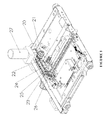
- FIG. 3 is a schematic diagram of a drive device according to the present invention without a chassis
- FIG. 4D is a cross sectional view of a portion of the structure diagram depicted in FIG. 4A .
- FIG. 4E is an enlarged view of the bounded area labeled 4 E in FIG. 4C .
- FIG. 2 is a structure diagram of a drive device according to a preferred embodiment of the present invention
- FIG. 3 is a schematic diagram of a drive device according to the present invention without a chassis.
- the drive device for a middle-high voltage vacuum circuit breaker chassis according to the present invention only has one-level transmission chain; it comprises a drive motor 10 , a clutch 11 , a drive chain wheel 12 , a driven chain wheel 13 , a chain 14 and a lead screw 15 .
- the clutch 11 is installed on an output shaft of the drive motor 10 ; the drive chain wheel 12 is fixed with the clutch 11 ; the drive chain wheel 12 is connected to the driven chain wheel 13 through the chain 14 ; and the driven chain wheel 13 is fitted over the lead screw so as to drive the lead screw 15 to rotate together.
- the drive chain wheel 12 is driven to rotate by the drive motor 10 through the clutch 11 , and the driven chain wheel 13 fitted over the lead screw 15 is driven to rotate by the drive chain wheel 12 through the chain 14 , so as to make the lead screw 15 rotate to drive the chassis to go forwards or backwards.
- the chain when the chassis is used for a smaller circuit breaker, the chain can be replaced by a belt.
- the advantage of using the belt is that if there is any problem on the logic control of the motor, the belt may break off, so that the motor or the circuit breaker will not be damaged.
- the motor or the circuit breaker when a chain is used, the motor or the circuit breaker will be easily damaged since the chain is relatively hard and cannot break off.
- a brushless direct current motor integrated with a logic control unit, as well as a permanent magnetic direct current motor may also be directly used as the drive motor. Since the brushless direct current motor has the logic control unit itself, a special motor controller is not needed, so that the cost is lower.
- a logic control table is shown as follows:
- Telesignalization status Switch- Switch- Work Test on off Operation status location location location location location Enable to pull in the handcart 0 x 0 1 Stop To “work 1 x x x pulling location” in the The “switch- x x x 0 handcart off location” is disabled Enable to pull out the handcart x 0 0 1 Stop to “test x 1 x x pulling location” out the The “switch- x x x 0 handcart off location” is disabled
- the same function as that of the existing drive device can be implemented through the drive device for a middle-high voltage vacuum circuit breaker chassis according to the present invention with one-level transmission chain only. Therefore, the drive device is simple in design, has fewer components, is convenient to install, and has a lower cost.
- FIGS. 4A-4C is a structure diagram of a drive device according to a prefer embodiment of the present invention.
- FIG. 4A shows a chassis in a working position.
- FIG. 4B shows a chassis in an isolation position
- FIG. 4C shows a chassis in a test position.
- a drive and control interlock device of a middle-high voltage circuit breaker chassis comprises a drive motor 10 , a clutch 11 , a drive chain wheel 12 , a position locking device 39 , an unlocking electromagnet 30 , a drive control microswitch 32 , a working position control microswitch 33 , and an isolation position control microswitch 35 .
- Clutch 11 is mounted on an output shaft of the drive motor 10 , and the drive chain wheel 12 is directly fixed with the clutch 1 the drive motor 10 drives the drive chain wheel 12 via clutch 11 .
- the chassis When the position locking device 39 is inserted into a recess 37 a , 37 b , 37 c of the lead screw 15 , the chassis is locked and the drive control microswitch 32 for the motor circuit is in an open state, and the chassis is unable to be driven no matter by manual or by electricity power.
- the circuit for unlocking electromagnet 30 Once the circuit for unlocking electromagnet 30 is closed, the movement of the iron core 36 of the electromagnet 30 , such as, for example, movement from a position shown in FIGS. 4B and 4C to a position shown in FIGS. 4A and 4D , makes the position locking device 39 move away from the recess 37 a , 37 b , 37 c on the lead screw 15 (see e.g., FIG.
- a pressing plate in linkage moves and actuates the working position control microswitch 33 for the motor circuit to be closed, the motor circuit is closed, and the drive motor 10 drives the drive chain wheel 12 via the clutch 11 , as well as the driven chain wheel 13 , and the chain 14 or a belt.
- the driven chain wheel 13 is sleeved on the lead screw 15 ; the drive chain wheel 12 drives the driven chain wheel 13 via the chain 14 , to bring the lead screw 15 to rotate together.
- the position locking device 39 slides along the surface of the lead screw 15 , and when it arrives at a followed recess 37 a , 37 b , 37 c on the lead screw 15 , the position locking device 39 falls into the recess 37 a , 37 b , 37 c under the action of a spring and the weight of itself, locking the chassis into its present position. Meanwhile, the pressing plate 31 in linkage actuates the working position control microswitch 33 for the motor circuit to shut off the motor circuit, and the drive motor is stopped to rotate.
- the working position control microswitch 33 When the chassis moves forwards to the working position, the working position control microswitch 33 is actuated by the pressing plate 38 , indicating that the chassis arrives at the working position, meanwhile, the swinging in circuit of the drive motor 10 is shut off, so that the drive motor 10 would not swing in the chassis even if the drive motor receives a signal for swinging in chassis, so as to avoid misoperation.
- the isolation position control microswitch 35 When the chassis is swung out of the isolation position, the isolation position control microswitch 35 is actuated by a pressing block 34 , indicating that the chassis arrives at the isolation position; meanwhile, the swinging out circuit of the drive motor 10 is shut off, so that the drive motor would not swing out the chassis even if the drive motor receives a signal for swinging out the chassis, so as to avoid misoperation.
- a vertically outstanding drive motor 27 which may interfere with the circuit breaker is arranged in the drive device for a middle-high voltage vacuum circuit breaker chassis of the prior art. Therefore, such a chassis can be only used in some circuit breakers.
- the drive motor 10 and the lead screw 15 of the chassis are arranged on the same plane or parallel planes (relative to the vertical arrangement of the prior art) according to the drive device for a middle-high voltage vacuum circuit breaker chassis in the present invention, and vertical arrangement is not adopted, so that no interference from the circuit breaker is involved. Therefore, such a chassis can be applicable to all circuit breakers.
Landscapes
- Engineering & Computer Science (AREA)
- Power Engineering (AREA)
- General Engineering & Computer Science (AREA)
- Mechanical Engineering (AREA)
- Trip Switchboards (AREA)
- Connection Of Motors, Electrical Generators, Mechanical Devices, And The Like (AREA)
Abstract
Description
| Telesignalization status | ||
| Switch- | Switch- | |||
| Work | Test | on | off |
| Operation status | location | location | location | location |
| Enable to pull in the handcart | 0 | x | 0 | 1 |
| Stop | To “work | 1 | x | x | x |
| pulling | location” | ||||
| in the | The “switch- | x | x | x | 0 |
| handcart | off location” | ||||
| is disabled |
| Enable to pull out the handcart | x | 0 | 0 | 1 |
| Stop | to “test | x | 1 | x | x |
| pulling | location” | ||||
| out the | The “switch- | x | x | x | 0 |
| handcart | off location” | ||||
| is disabled | |||||
Claims (19)
Applications Claiming Priority (3)
| Application Number | Priority Date | Filing Date | Title |
|---|---|---|---|
| CN201621424598.8U CN206471986U (en) | 2016-12-23 | 2016-12-23 | Drive for vacuum circuit breaker chassis |
| CN201621424598U | 2016-12-23 | ||
| CN201621424598.8 | 2016-12-23 |
Publications (2)
| Publication Number | Publication Date |
|---|---|
| US20180183220A1 US20180183220A1 (en) | 2018-06-28 |
| US10312670B2 true US10312670B2 (en) | 2019-06-04 |
Family
ID=59712615
Family Applications (1)
| Application Number | Title | Priority Date | Filing Date |
|---|---|---|---|
| US15/656,833 Active US10312670B2 (en) | 2016-12-23 | 2017-07-21 | Drive device for vacuum circuit breaker chassis |
Country Status (2)
| Country | Link |
|---|---|
| US (1) | US10312670B2 (en) |
| CN (1) | CN206471986U (en) |
Cited By (2)
| Publication number | Priority date | Publication date | Assignee | Title |
|---|---|---|---|---|
| US20230194609A1 (en) * | 2021-12-21 | 2023-06-22 | Jst Power Equipment, Inc. | Testing system that determines contact erosion in circuit breaker |
| US11735893B2 (en) * | 2021-02-25 | 2023-08-22 | Jst Power Equipment, Inc. | Switchgear system having chain driven circuit breaker and associated methods |
Families Citing this family (6)
| Publication number | Priority date | Publication date | Assignee | Title |
|---|---|---|---|---|
| CN110718876B (en) * | 2019-11-27 | 2024-07-23 | 山西汾西电气有限公司 | Manual and automatic integrated driving mechanism for circuit breaker isolating body |
| CN110797786B (en) * | 2019-11-27 | 2024-07-23 | 山西汾西电气有限公司 | Manual and automatic integrated push-type circuit breaker isolation body in mining high-voltage power distribution cabinet |
| CN112736744B (en) * | 2020-12-31 | 2025-08-26 | 温州盛川机电制造有限公司 | High-voltage switchgear operating mechanism |
| CN113517649B (en) * | 2021-05-31 | 2024-04-12 | 上海电气集团股份有限公司 | Transmission structure for chassis vehicle |
| CN113990715A (en) * | 2021-11-12 | 2022-01-28 | 江苏洛凯机电股份有限公司 | Double shaft drive circuit breaker |
| CN120637132B (en) * | 2025-08-18 | 2025-12-02 | 浙江正泰电气科技有限公司 | Circuit breaker interlocking device and circuit breaker |
Citations (11)
| Publication number | Priority date | Publication date | Assignee | Title |
|---|---|---|---|---|
| US4763219A (en) * | 1986-11-14 | 1988-08-09 | Tsubakimoto Chain Co. | Overload protection for DC motor-driven linear actuator |
| US4857783A (en) * | 1988-02-18 | 1989-08-15 | James N. Papanicolas | Brushless direct current motor incorporating a magnetically influenced switch |
| US8304672B2 (en) * | 2009-12-21 | 2012-11-06 | Schneider Electric USA, Inc. | Wireless remote racking mechanism |
| US8395064B2 (en) * | 2009-12-23 | 2013-03-12 | Ls Industrial Systems Co., Ltd. | Interlock apparatus of ground switch for vacuum circuit breaker |
| US8410389B2 (en) * | 2009-12-29 | 2013-04-02 | Schneider Electric USA, Inc. | Remote drive for disconnector/isolator used in switchgear |
| US8420964B2 (en) * | 2010-10-12 | 2013-04-16 | Eaton Corporation | Electrical apparatus, and racking assembly and coupling therefor |
| US8476993B1 (en) * | 2012-03-28 | 2013-07-02 | Cleaveland/Price Inc. | Motor operator with positive decoupling and maximum force application for electrical power switches |
| WO2013143415A1 (en) * | 2012-03-28 | 2013-10-03 | 伊顿电气有限公司 | Electric chassis vehicle for circuit breaker |
| CN203312685U (en) * | 2013-05-30 | 2013-11-27 | 厦门华泰利机电有限公司 | Motor drive structure for horizontal electric chassis, and electric chassis |
| US20150114807A1 (en) * | 2013-10-31 | 2015-04-30 | Eaton Corporation | Withdrawable contactor trucks with integral motorized levering-in, related swtichgear, kits and methods |
| US9843173B2 (en) * | 2014-02-06 | 2017-12-12 | Abb Technology Ag | Switchgear apparatus of the withdrawable type |
-
2016
- 2016-12-23 CN CN201621424598.8U patent/CN206471986U/en active Active
-
2017
- 2017-07-21 US US15/656,833 patent/US10312670B2/en active Active
Patent Citations (11)
| Publication number | Priority date | Publication date | Assignee | Title |
|---|---|---|---|---|
| US4763219A (en) * | 1986-11-14 | 1988-08-09 | Tsubakimoto Chain Co. | Overload protection for DC motor-driven linear actuator |
| US4857783A (en) * | 1988-02-18 | 1989-08-15 | James N. Papanicolas | Brushless direct current motor incorporating a magnetically influenced switch |
| US8304672B2 (en) * | 2009-12-21 | 2012-11-06 | Schneider Electric USA, Inc. | Wireless remote racking mechanism |
| US8395064B2 (en) * | 2009-12-23 | 2013-03-12 | Ls Industrial Systems Co., Ltd. | Interlock apparatus of ground switch for vacuum circuit breaker |
| US8410389B2 (en) * | 2009-12-29 | 2013-04-02 | Schneider Electric USA, Inc. | Remote drive for disconnector/isolator used in switchgear |
| US8420964B2 (en) * | 2010-10-12 | 2013-04-16 | Eaton Corporation | Electrical apparatus, and racking assembly and coupling therefor |
| US8476993B1 (en) * | 2012-03-28 | 2013-07-02 | Cleaveland/Price Inc. | Motor operator with positive decoupling and maximum force application for electrical power switches |
| WO2013143415A1 (en) * | 2012-03-28 | 2013-10-03 | 伊顿电气有限公司 | Electric chassis vehicle for circuit breaker |
| CN203312685U (en) * | 2013-05-30 | 2013-11-27 | 厦门华泰利机电有限公司 | Motor drive structure for horizontal electric chassis, and electric chassis |
| US20150114807A1 (en) * | 2013-10-31 | 2015-04-30 | Eaton Corporation | Withdrawable contactor trucks with integral motorized levering-in, related swtichgear, kits and methods |
| US9843173B2 (en) * | 2014-02-06 | 2017-12-12 | Abb Technology Ag | Switchgear apparatus of the withdrawable type |
Non-Patent Citations (2)
| Title |
|---|
| Translation CN203312685 (Original document filed Nov. 27, 2013). * |
| Translation of WO2013143415 (Original doc. published Oct. 3, 2013) (Year: 2013). * |
Cited By (5)
| Publication number | Priority date | Publication date | Assignee | Title |
|---|---|---|---|---|
| US11735893B2 (en) * | 2021-02-25 | 2023-08-22 | Jst Power Equipment, Inc. | Switchgear system having chain driven circuit breaker and associated methods |
| US12027830B2 (en) | 2021-02-25 | 2024-07-02 | Jst Power Equipment, Inc. | Switchgear system having chain driven circuit breaker and associated methods |
| US20230194609A1 (en) * | 2021-12-21 | 2023-06-22 | Jst Power Equipment, Inc. | Testing system that determines contact erosion in circuit breaker |
| US11860230B2 (en) * | 2021-12-21 | 2024-01-02 | Jst Power Equipment, Inc. | Testing system that determines contact erosion in circuit breaker |
| US12360163B2 (en) | 2021-12-21 | 2025-07-15 | Jst Power Equipment, Inc. | Testing system that determines contact erosion in circuit breaker |
Also Published As
| Publication number | Publication date |
|---|---|
| CN206471986U (en) | 2017-09-05 |
| US20180183220A1 (en) | 2018-06-28 |
Similar Documents
| Publication | Publication Date | Title |
|---|---|---|
| US10312670B2 (en) | Drive device for vacuum circuit breaker chassis | |
| CN103155315B (en) | Switchgear with internal arc protection | |
| CN104319130B (en) | Operating mechanism and blocking device thereof | |
| CN108364837A (en) | The automatic division gate controlling mechanism of novel small-sized breaker and breaker | |
| CN105406386B (en) | The interlock of valve and earthing switch | |
| CN106067409A (en) | The external chopper of electric energy meter | |
| CN101763977B (en) | Driving mechanism for isolating switch | |
| CN205595264U (en) | Be suitable for isolator of narrow and small space divide -shut brake | |
| CN104934246A (en) | Emergency switch-off module of breaker | |
| KR102121524B1 (en) | Modularized auxiliary contact and current circuit breaker having simple structure | |
| US2864911A (en) | Mechanism for motor operation of a circuit breaker | |
| AU2014203187B2 (en) | Lockout device for switchgear | |
| CN209786546U (en) | Anti-electricity-theft electric energy distribution box | |
| CN105762695B (en) | Switch cabinet for electrical switching apparatus and method of assembling the same | |
| CN103295806A (en) | Manual-and-electric switching-on switching-off dual-function permanent magnetic mechanism with protective chain | |
| CN211578633U (en) | A kind of anti-charged mis-closing grounding knife switch device | |
| CN204577306U (en) | A kind of use for electric locomotive earthed switch | |
| CN103700534A (en) | Transitional motion three-position isolating switch over-position protection device | |
| CN205248181U (en) | Permanent magnetism of manual separating brake divides closing operation mechanism | |
| CN113130222B (en) | Remote operating mechanism of an electric operating switch | |
| CN203669526U (en) | A Translating AB Door Interlock Control System Applicable to Harsh Environment | |
| CN109360753B (en) | Mechanical interlocking device of medium-voltage dual-power automatic change-over switch and dual-power device | |
| US1686708A (en) | Automatic magnetic release for ironing machines | |
| CN107063650A (en) | Vehicle glass lifting mechanism service life test device and its method | |
| CN218447770U (en) | Novel mechanical interlocking structure of SF6 circuit breaker |
Legal Events
| Date | Code | Title | Description |
|---|---|---|---|
| AS | Assignment |
Owner name: ABB SCHWEIZ AG, SWITZERLAND Free format text: ASSIGNMENT OF ASSIGNORS INTEREST;ASSIGNORS:ZHANG, XIN;WANG, ZHIAN;ZHUANG, ZHIJIAN;REEL/FRAME:043073/0320 Effective date: 20170705 |
|
| STPP | Information on status: patent application and granting procedure in general |
Free format text: NOTICE OF ALLOWANCE MAILED -- APPLICATION RECEIVED IN OFFICE OF PUBLICATIONS |
|
| STPP | Information on status: patent application and granting procedure in general |
Free format text: PUBLICATIONS -- ISSUE FEE PAYMENT VERIFIED |
|
| STCF | Information on status: patent grant |
Free format text: PATENTED CASE |
|
| MAFP | Maintenance fee payment |
Free format text: PAYMENT OF MAINTENANCE FEE, 4TH YEAR, LARGE ENTITY (ORIGINAL EVENT CODE: M1551); ENTITY STATUS OF PATENT OWNER: LARGE ENTITY Year of fee payment: 4 |