US1031202A - Apparatus for forming castings. - Google Patents
Apparatus for forming castings. Download PDFInfo
- Publication number
- US1031202A US1031202A US52613809A US1909526138A US1031202A US 1031202 A US1031202 A US 1031202A US 52613809 A US52613809 A US 52613809A US 1909526138 A US1909526138 A US 1909526138A US 1031202 A US1031202 A US 1031202A
- Authority
- US
- United States
- Prior art keywords
- track
- wheel
- cable
- conveyer
- flasks
- Prior art date
- Legal status (The legal status is an assumption and is not a legal conclusion. Google has not performed a legal analysis and makes no representation as to the accuracy of the status listed.)
- Expired - Lifetime
Links
Images


Classifications
-
- B—PERFORMING OPERATIONS; TRANSPORTING
- B22—CASTING; POWDER METALLURGY
- B22D—CASTING OF METALS; CASTING OF OTHER SUBSTANCES BY THE SAME PROCESSES OR DEVICES
- B22D25/00—Special casting characterised by the nature of the product
- B22D25/02—Special casting characterised by the nature of the product by its peculiarity of shape; of works of art
- B22D25/04—Casting metal electric battery plates or the like
Definitions
- the object in view generically is the arrangement of means for casting and conveying metal ware.
- Another object in view is the arrangement o fmeansfor'conveying flasks or molds, as
- sociatedwith means for pouring the same, manufacturing the flasks, tumbling and finishing thel-warezmolded in the flasks, and
- transporting means for conveying the finish'ed ware-to a desired point.
- the invention comprises certain novel constructions', conihinatibns, and arrangement of parts 'as'w'illbe hereinafter more fully de- 3 5 clamps used'in "securing the carrier arm scribed and" claimed.
- Fig. 3 is an enlarged fragm'enta1ty"top plan view of the conveyor shown inFig. 1'.' 4- is a side elevation i of'thest'rh' t are shown in Fig. 3.
- Fig. 5 is an enlarged 'vic'wgot sand carrying mechanisin, the shmebeing broken away to better
- Fig. 6 is an enlargei sh'iwn inFigjii to its: operating cable.
- Fig. 8 is an enlarged 59 detaihsectional view approximately on line SliOSY'TLllTtFlgI3
- Fig. 11 is an enlarged de Mairrnigmenmry view of one of the flask H c v Specification of Letters Patent.v Application flledllovemher s, 1909.
- Fig. 16 is a fragmentary sectional View... through the shake-out.
- Fig. 17 is a trans verse section through one of the sand distrib-' uting troughs and associated parts.
- a conveyer is provided of any desired size and length used for conveying flasks or molds to means for pouring metal therein, which means is arranged to continuously sup ly the molten-metal to the flasks as fast as tlie conveyor moves the same in proximity to the )ouring device. After the molds have been filled the conveyer moves ;the same away and at the same time a fresh or unfilled mold is moved beneath the pour ing device.
- the metal casting is designed to be moved by the shakc out to one side, and the sand is designed to be caught in a hopper and transported to molding machines for molding the flasks.
- the metal casting that has been automatically moved to one side by the shake-out device is manually placed in a tumbler from which it is passed to finishing mechanism of any desired kind. From the finishing mechanism the casting is placed upon conveying cars which eventually transport and deposit the casting at a warehouse or other desired Patented July 2, 1912.
- the sand disposed of by the automatic shake-out device is moved by suitable means to molding machines, together-with additional sand if desired for making new flasks which are manually placed upon the conveyer preparatory to being brought beneath the metal pouring device.
- the metal is continuously andQsucceSsiveIy operated upon from the time it is put in the ,cupola or melting device until it is finally discharged in the warehouse a finished product.
- 1 and 2 indicate cupolas or melting devices fed by suitable means as pipes 3. Valves 4 and 5 are provided for regulating the amount of material placed in the cupolas. Adjacent the melting means or cupolas 1 and 2 is a track 6 carrying a truck 7 of any desired structure upon which is mounted asuitable ladle 8, or pouring device, which is designed to be filled with metal from one of the cupolas 1 or-2, and then moved around in proximity to wheel 9 for pouring into flasks placed upon the supporting arms 10 when the same come opposite.
- the ladle 8 may be of any desired structure.
- a plurality of ladles 8 may be provided if desired, and. are suit-ably mounted upon trucks so as to be freely movable along track 6 as desired. I
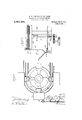
- the conveyer 11 is provided with a wheel 9 at one end, and a similar wheel 12 at the opposite end constructed, as more clearly shown in Fig. 3, for accommodating acable 13, and also accommodating the cable clamps 14.
- the clamps 14 a plurality of notches 15 are formed in wheels 9 and 12, and spaced apart properly for'receiving the, respective mem"- ber 14:.so that the wheels actin a certain sense as a sprocket wheel and the cable 13 and clamp 14 ,act in a certain sense as a chain.
- v Wheel 12' is mounted upon shaft 16, which in turn is mounted in suitable bearings of anydesired kind, and wheel 9,is secured to a shaft 17 mounted inbearings 18 and 19and is connected with a gear wheel 20 which receives power from any suitable source, (not shown), whereby the conveyer is moved as desired for causing the respective flask carrying arms 10 to come opposite the ladle 8.
- the flask carrying armslO (Fig. at) are each formed with an upright member 21 which is bent over into a hook shaped member 22 at the top and is arranged with an ofiset portion 23 at the bot-tom for receiving a bracket 24.
- Bracket 24 carries a grooved wheel 25 which travels upon a track 26 and supports arm 10 with .the assistance of wheel 27 journaled in the hook member 22.
- Grooved wheel 27 isdesigned to travel'upon track 28, which track isv supported by suitable standards 29, which standards also support track 26.
- the journal 30 of wheel 27 is rigidly secured to one partof the rope clamp 14 (Fig. 6) so as to positively travel therewith.
- the rope clamp 14 is made in two parts and secured together by suitable bolts 31.
- the part which carries the bearing shaft 30 has a raised portion centrally thereof, and the opposite partof course has a groove centrally thereof for accommodating the raised portion.
- A. longitudinal groove is formed in each part of the clamp 14 for accommodating cable 13 when'the parts are clamped together by bolts 31.
- the clamp 14 may be made cylindrical or rectangular as desired, and of a suflicient length for fitting into the notches or cut out portions 15 of wheels 9 and 12.
- the ladle 8 is designed to pour metal into the flasks on arms 10 when the same come opposite wheel 9, as shown in Fig. 3, and from thence the filled flasks are conveyed to wheel 12, around wheel 12,and back toward wheel 9 until the same reach a position opposite an automatic shake-out 32. At this point the track 26 is bent inward at 33 Figs.
- the wheel 25 will follow the in ward bending or curvature of the track, wh chwill necessarily cause the arms 10 to tilt and permit the flask thereon to slide off.
- the flask After sliding off arm 10 the flask will be caught by the automatic shake-out 32, which is placed in proximity to the curved portion 33 oftrack 26, and slightly below the same. After the flask has been dumped arm 10 will continue its movement, and will be raised to its ordinary position, whereupon a new flask is placed thereon, which is conveyed tothe pouring-point, and the flask filled, which is then conveyed around to a point opposite the automatic shake-out 32, as just set forth. 7
- the automatic shake-out comprises a framework having a plurality-of rods extending from one side to the other with one side of the frame somewhat higher than the opposite side. shaped chute, and to mechanism which shakes or gyrates the chute and frame. This gyratory or shaking movement causes the flask to be broken up and the casting therein to be moved to the lower side of the shakeout, and there dumped, from which it is removed and placed in tumblers 34.
- the casting is removed to drilling machines 35, if it is necessary .to provide holes therein, and then to finishing machines, as for instance lathes 36. From the lathes This frame is secured to a funnel- 36 .the finished casting is moved to car 37 on track 38, (Fig. 2), and from thence moved to a desired pomt, as for instance a wareho'us'e'as will be hereinafter fully described.
- sand From receptacle 40 the sand passes through a pipe 41 to an elevator 42. Elevator 42 conveys the sand upward to a trough 43 (Figs. 1 and 5).
- the trough 43 is of any desired size, and is provided with a cable 44 carrying a plurality of flights 45 which are disk-shaped. The lower part of the flight is designed to extend into trough 4-3, but not to touch the bottom thereof; Cable 44 passes around suitable pulleys 46, 47, 48 and 49 which are constructed so as to accommodate the flights 45. Power is appliedto pulleys 46 and 48 in any desired manner, as for instance, by securing a.
- Trough 48 (Fig. 1) is provided with a plurality of spouts or chutes '51 for discharging sand intoflask making machines 52.
- a suitable ate 53 is provided in'the chutes 51 for re u ating the amount of sand passing theret rough.
- a plurality of chutes 54 provided with suitable controlling-valves extendfrom the bottom of trough 43 to the respective tanks or bins-55,
- Trough'43 isprov-i'ded witha chute 57. at the end-opposite the elevator. 42 in order to permit the flights 45 to empty the-top trough 43 into the "bottom trough 50,11. suitable valve being provided for closing the chute whenever desired.
- the flights 45 are each divided into equal halves, the clamp 58 being a-portion of the flight, a recess or. groove extending longitu dinally of each part of the clamp permits of the clamping of the cable 44, and also the axle 59 whichfits in a trans-verse groove in the flightp
- the aXle 59 carries rollers 60 at each end which rest upon angle iron 61 secured tothe respective troughs.
- a track conveyor 62 Associated with the conveyer 11 is a track conveyor 62.
- the track conveyer 62 is providedwith a track 38, cars'37 and track 63.
- Track 38 is designed to extend from near where the castings are finished to a warehouse or storage place, and track 63 isthe-ret'urntra'c'k for cars 37.
- the cars are moved by Cable 64 (Fi 7).
- Cable 64 (Fi 7).
- the cable (34 passes over puli..-ys (17 and 8 which are constructed for permitting the passage around the same of clamps en.
- the shaft upon which pulley 67 is secured is rotated by any desired means for moving the cable.
- the respective cable clamps 6 are each provided with a shaft or axle ()9 for accommodating wheel which engages the floor or a prepared track as desired for properly supporting the cable 68 for causing lugs 66 to engage cars 37.
- a gutter is provided in which-are arranged tracks 7-1 on which the wheels 70 roll.
- the utter is made of such adcpth as to permit the un obstructed return of lugs 66.
- the cable 64 is given an intermittent motionhy lever 7 2 which controls the clutch forthrowing on and off power from the shaft carryin pulley 67. This is necessary in order t at the cars may stop at theright oint for being unloaded.- After acar has con unloaded the lever 72 is operated for causing cable 64. to move. Thiswillmcve 7i past switc 76 "the same will pass own-' ward around pulley 77' which is driven by any desired power and which accommodates thecable 75 and the respective lugs 74 and rope clamps 78.
- An idler is positioned at the opposite end of cable'75 for accommodating thecable so as to hold the cable taut and in proper position for engaging the empty cars as'the same start up the incline track 73.
- the switch 76' isa spring actuated switch, and will permit the cars to pass therethrough, but afteca carhas passed the switch will automatically close for switching the empty car onto track 63, Track 63' is inclined from switch 76 to a point 79. From point 79 the-track 63 is lnclined upwardly past switch 80 which is constructed similar to switch 76. The 'momentum of the empty car will cause the same to move up the incline between point79 and as to' permit the cars to be loaded 8,1?0118 upon which pulley wheel 85 is mounted.
- Figs. 10 to 14 inclusive a slightly modified form of flask or mold carrying conveyer which if desired may take the place of the preferred form of carrier 11 shown in Fig. 1.
- This conveyer is provided with an upper track 81 and a lower or return track 82.
- the upper track 81 has associated therewith a guide rail 83 arranged in proximity to the lower track 82 and the lower or return track 82 is provided with a guide rail 84:.
- Track 81 is supportedby any suitable supports and extends from pulley wheel 85 to pulley wheel 86.
- the upper track 81 is bent into a semicircular hook of less diameter than wheel 86 and at wheel 85 it is similarly constructed so as to freely receive the grooved wheels 87 from the lower track 82, which is formed with a hook-shaped member similar to the upper track, except that the same is struck upon the arc of a circle having a larger diameter than the wheels 85 and 86.
- the wheels 87 are'connected to the flask carrying arms 10 similar to the way in which the preferred form is shown, and is also associated with an operating cable 13' which is constructed and operates similarto cable 13.
- a caster 25 is provided which rolls upon the guiding rolls 83 and 84.
- the flask carrying arms 10 are constructed similar to the arms 10 of the preferred structure, but
- the pulley wheels 85 and 86 rotate in a vertical plane, and are driven by any suitable power connected with the shaft
- the flask is put on the arm at any desired point, and is preferably filled shortly before the arm passes around wheel 86.
- the rope clamp associated therewith will engage one of the notches of the wheel, and firmly support the arm, together with the flask as the shaft or axle '87 is rigidly securedto the rope clamp, and passes loosely through the upper part of arm 10. ;As the wheel 86'rotates the arm will be gradually lowered as shown'in Fig.10.
- a section or short length-portion 88 of rail 83 is lowcred until the same comes into alinem'ent with rail 84.
- section 88 of rail 82 and also section 88' are each operated by any desired means connected with shafts carrying wheels -85a'nd 86 so as to raise and lower the sections in proper timed relationship to the movement of the pulleys.
- a reservoir for -molten metal a traveling ladle adapted to distribute metal from said reservoir, a conveyer for-conveying flasks in proximity to said ladle for being filled thereby and then transporting the filled ladle to a discharge point, a track for guiding said conveyer bent out of the line of its general direction at the discharge point for tilting said conveyer at said point whereby each of the flasks upon reaching said point will be automatically dumped from the conveyer.
- a reservoir for the manufacture of castings, a reservoir, a ladle for distributing metal from said reservoir, a conveyer for conveying flasks in proximity to said ladle for being filled thereby, s'aid conveyer comprising a pair of wheels, a cable mounted on said wheels, and flasks supporting arms secured to said cable, and a guide rail for said flask carrying arms formed with a depression for tilt-ing said arms, whereby said flasks are dumped from said conveyer.
- a conveyer comprising a pair of pulley wheels formed with notches therein, a cable positioned on said pulley wheels, cable gripping members surrounding said cable at intervals and arranged to engage the notches in said wheels, a flask carrying arm connected with each of. said cable grips, a guide rail' forguiding said carrying arm and formed with a depression for inclining said carrying arm for dumping flasks therefrom, and means for supplying the flasks on said conveyer with metal.
- a conveyer for moving flasks comprising a pair of spaced pulleys, a cable passing around said pulleys, a flask suplower end of said casting,
- bracmgrall belng formed with a bent 1n portlonfor causing sald arm to be moved at an angle to'the plane in which said arm normally travels for causing the flask thereon to be dumped therefrom, and means for supplying the flask on said arm with molten metal.
- an automatic flask shake-out for separating the sand of'theflask from the a plurality of 'means for. pouring and conveying said flasks to the automatic arm, and anti-friction shake-out, and a conveyer for conveying the castings from said shake-out to a storage point
- said conveyer comprising a track, a plurality of cars mounted on said track, an endless cable formed with flights thereon for engaging said cars, means for causing said cable to move intermittently, and an inclined track for returning gravity to the starting point.
Description
APPARATUS FOR FORMING CASTINGS.
APPLIOATION FILED NOV. 3, 1909.
Patented July 2, 1912.
6 SHEETS-SHEET 1.
Q\ m I I WWFWFE a Fur Lu I l... I I lmmmmmmmmm mnmwflmmn 3n ue l-vrowf Q/Vibncooca E. W. SAMPLE & W. H. BASON.
APPARATUS FOR FORMING OASTINGS.
APPLICATION FILED NOV. 3, 1909.
1,031,202. 7 Patented Ju1y2, 1912.
6 SHEETS-811E312.
E. W. SAMPLE & W. H. BASON. APPARATUS FOR FORMING GASTINGS. APPLICATION rump NOV. a, 1909.
1,031,202. Patented July 2, 1912.
6 SHBETSBHEET 3.
E.'W. SAMPLE & w. H. BASON.
APPARATUS FOR FORMING CASTINGS.
APPLICATION FILED NOV. 3, 1909,
' Patented July 2, 1912.
6 SHEETS-SHEET 4.
E. W. SAMPLE & w. HJBASON.
APPARATUS FOR FORMING CASTINGS.
APPLICATION FILED NOV-3,1909. 15,031,202 Patented July 2, 1912.
6 SHEETS-SHEET 5.
\ v Y 81A amm' ror/ E. W. SAMPLE & W. H. BASON.
APPARATUS FOR FORMING GASTINGS.
1,031,202. Patented July 2, 1912.
I 6 EEEEEEEEEEEE 6.
g Be *it" known" that we; ELMoRn W, SAMPLE rand; Wn'anAM I-LBAsoN, citizens of the United States, residing at Birmingham, in
"the county of Jefierson and Stateof Alabama; have'inventedcertain new and useful Improvements Apparatus for Forming Gastmgs;'-and wedo hereby declare the fol lowingto barren; clear, and exact description of the invention, such will enable others skilledin the art to wI. ch it appertains to rnake'and use the same.
1 "This inventionr elates to improvements in associated apparatus and arrangement of means" for casting. metal and distributing the same to a: predetermined point.
'l-The object in view generically is the arrangement of means for casting and conveying metal ware.
.20 Another object in view is the arrangement o fmeansfor'conveying flasks or molds, as
sociatedwith means for pouring the same, manufacturing the flasks, tumbling and finishing thel-warezmolded in the flasks, and
transporting means for conveying the finish'ed ware-to a desired point.
'-"W"thithe'se and other ob 'ects in view the invention comprises certain novel constructions', conihinatibns, and arrangement of parts 'as'w'illbe hereinafter more fully de- 3 5 clamps used'in "securing the carrier arm scribed and" claimed.
ing cei'tain fe atu'res of the invention. 2 181splan' VIGW'OLE a system of conveying means-for conveying articles from the conveyer-shown1n F1g. 1. Fig. 3 is an enlarged fragm'enta1ty"top plan view of the conveyor shown inFig. 1'.' 4- is a side elevation i of'thest'rh' t are shown in Fig. 3. Fig. 5 is an enlarged 'vic'wgot sand carrying mechanisin, the shmebeing broken away to better Fig. 6 is an enlargei sh'iwn inFigjii to its: operating cable. Fig. 711s a1diagramniat1c edge vlew of the conveyerishown mFigIQ. Fig. 8 is an enlarged 59 detaihsectional view approximately on line SliOSY'TLllTtFlgI3 Fig. 11 is an enlarged de Mairrnigmenmry view of one of the flask H c v Specification of Letters Patent.v Application flledllovemher s, 1909.
I, UNITED S ATES PATENT OFFICE.
Ann wirmmr m -main, ALABAMA.
mamas FOR FORMING cns rmes- Serial No. 528,138.
Fig. 16 is a fragmentary sectional View... through the shake-out. Fig. 17 is a trans verse section through one of the sand distrib-' uting troughs and associated parts.
In constructing means embodyingthe invention the various parts or structures there of are designed to be arranged for accomplishing a single purpose or end, though a plurality of distinct structures are used, but arranged in interdependent sequence, so that each succeeding structure -depends for its most successful operation upon the one immediately preceding. A conveyer is provided of any desired size and length used for conveying flasks or molds to means for pouring metal therein, which means is arranged to continuously sup ly the molten-metal to the flasks as fast as tlie conveyor moves the same in proximity to the )ouring device. After the molds have been filled the conveyer moves ;the same away and at the same time a fresh or unfilled mold is moved beneath the pour ing device. As the filled molds or flasks are moved away the same are cooled gradually until the molten metal therein has congealed. The conveyor continues to move the flasks even after the molten metaltherein has con gealed for a short distance, and then auto-.
matically dumps the flasks and metal contained therein onto an automatic shake-out device for separating the metal casting from the sand of the mold. The metal casting is designed to be moved by the shakc out to one side, and the sand is designed to be caught in a hopper and transported to molding machines for molding the flasks. The metal casting that has been automatically moved to one side by the shake-out device is manually placed in a tumbler from which it is passed to finishing mechanism of any desired kind. From the finishing mechanism the casting is placed upon conveying cars which eventually transport and deposit the casting at a warehouse or other desired Patented July 2, 1912.
point. The sand disposed of by the automatic shake-out device is moved by suitable means to molding machines, together-with additional sand if desired for making new flasks which are manually placed upon the conveyer preparatory to being brought beneath the metal pouring device. By thus associating various means the metal is continuously andQsucceSsiveIy operated upon from the time it is put in the ,cupola or melting device until it is finally discharged in the warehouse a finished product.
In order that the invention may be more clearly understood -an embodiment'of the same is shown in the accompanying drawings in which 1 and 2 indicate cupolas or melting devices fed by suitable means as pipes 3. Valves 4 and 5 are provided for regulating the amount of material placed in the cupolas. Adjacent the melting means or cupolas 1 and 2 is a track 6 carrying a truck 7 of any desired structure upon which is mounted asuitable ladle 8, or pouring device, which is designed to be filled with metal from one of the cupolas 1 or-2, and then moved around in proximity to wheel 9 for pouring into flasks placed upon the supporting arms 10 when the same come opposite. The ladle 8 may be of any desired structure. A plurality of ladles 8 may be provided if desired, and. are suit-ably mounted upon trucks so as to be freely movable along track 6 as desired. I
The conveyer 11 is provided with a wheel 9 at one end, and a similar wheel 12 at the opposite end constructed, as more clearly shown in Fig. 3, for accommodating acable 13, and also accommodating the cable clamps 14. In order to accommodate, the clamps 14: a plurality of notches 15 are formed in wheels 9 and 12, and spaced apart properly for'receiving the, respective mem"- ber 14:.so that the wheels actin a certain sense as a sprocket wheel and the cable 13 and clamp 14 ,act in a certain sense as a chain. v Wheel 12' is mounted upon shaft 16, which in turn is mounted in suitable bearings of anydesired kind, and wheel 9,is secured to a shaft 17 mounted inbearings 18 and 19and is connected with a gear wheel 20 which receives power from any suitable source, (not shown), whereby the conveyer is moved as desired for causing the respective flask carrying arms 10 to come opposite the ladle 8.
The flask carrying armslO (Fig. at) are each formed with an upright member 21 which is bent over into a hook shaped member 22 at the top and is arranged with an ofiset portion 23 at the bot-tom for receiving a bracket 24. Bracket 24 carries a grooved wheel 25 which travels upon a track 26 and supports arm 10 with .the assistance of wheel 27 journaled in the hook member 22.
The ladle 8 is designed to pour metal into the flasks on arms 10 when the same come opposite wheel 9, as shown in Fig. 3, and from thence the filled flasks are conveyed to wheel 12, around wheel 12,and back toward wheel 9 until the same reach a position opposite an automatic shake-out 32. At this point the track 26 is bent inward at 33 Figs.
.1 and 15). The wheel 25 will follow the in ward bending or curvature of the track, wh chwill necessarily cause the arms 10 to tilt and permit the flask thereon to slide off.
After sliding off arm 10 the flask will be caught by the automatic shake-out 32, which is placed in proximity to the curved portion 33 oftrack 26, and slightly below the same. After the flask has been dumped arm 10 will continue its movement, and will be raised to its ordinary position, whereupon a new flask is placed thereon, which is conveyed tothe pouring-point, and the flask filled, which is then conveyed around to a point opposite the automatic shake-out 32, as just set forth. 7
After the flasks have been dumped upon the automatic shake-out 32 the same, by its movement, moves the casting to one side, and breaks-up the sand of themold, which passes downward into a chute below the shake-out and, in fact, forming part thereof. The automatic shake-out comprises a framework having a plurality-of rods extending from one side to the other with one side of the frame somewhat higher than the opposite side. shaped chute, and to mechanism which shakes or gyrates the chute and frame. This gyratory or shaking movement causes the flask to be broken up and the casting therein to be moved to the lower side of the shakeout, and there dumped, from which it is removed and placed in tumblers 34. From the tumblers 34 the casting is removed to drilling machines 35, if it is necessary .to provide holes therein, and then to finishing machines, as for instance lathes 36. From the lathes This frame is secured to a funnel- 36 .the finished casting is moved to car 37 on track 38, (Fig. 2), and from thence moved to a desired pomt, as for instance a wareho'us'e'as will be hereinafter fully described.
and dainpens the same to a proper consistency. From receptacle 40 the sand passes through a pipe 41 to an elevator 42. Elevator 42 conveys the sand upward to a trough 43 (Figs. 1 and 5). The trough 43 is of any desired size, and is provided with a cable 44 carrying a plurality of flights 45 which are disk-shaped. The lower part of the flight is designed to extend into trough 4-3, but not to touch the bottom thereof; Cable 44 passes around suitable pulleys 46, 47, 48 and 49 which are constructed so as to accommodate the flights 45. Power is appliedto pulleys 46 and 48 in any desired manner, as for instance, by securing a. ulley to each of the shafts carryiiig these pa leys, and applying a power belt thereto. The power is appliedto these pulleys. in order to give a direct'pull on the respective flights 45 moving the sand to troughs 43' and 50 Trough 48 (Fig. 1) is provided with a plurality of spouts or chutes '51 for discharging sand intoflask making machines 52. A suitable ate 53 is provided in'the chutes 51 for re u ating the amount of sand passing theret rough. A plurality of chutes 54 provided with suitable controlling-valves extendfrom the bottom of trough 43 to the respective tanks or bins-55,
which-contain avsupplyof fresh sand. The
' tanks or bins-55 are provided with sliding the amountof sand doorsor' gates 56' (F1 9) which regulate discharged. from the tanks or binsinto the lower trough 50. Trough'43 isprov-i'ded witha chute 57. at the end-opposite the elevator. 42 in order to permit the flights 45 to empty the-top trough 43 into the "bottom trough 50,11. suitable valve being provided for closing the chute whenever desired.
The flights 45 are each divided into equal halves, the clamp 58 being a-portion of the flight, a recess or. groove extending longitu dinally of each part of the clamp permits of the clamping of the cable 44, and also the axle 59 whichfits in a trans-verse groove in the flightp The aXle 59 carries rollers 60 at each end which rest upon angle iron 61 secured tothe respective troughs.
Associated with the conveyer 11 is a track conveyor 62. The track conveyer 62 is providedwith a track 38, cars'37 and track 63. Track 38 is designed to extend from near where the castings are finished to a warehouse or storage place, and track 63 isthe-ret'urntra'c'k for cars 37. The cars are moved by Cable 64 (Fi 7). In order to convey ngaging the respective cars 37, as more clearly seen in Fig. 8, for. moving the same along track 38. The cable (34 passes over puli..-ys (17 and 8 which are constructed for permitting the passage around the same of clamps en. The shaft upon which pulley 67 is secured is rotated by any desired means for moving the cable. The respective cable clamps 6:) are each provided with a shaft or axle ()9 for accommodating wheel which engages the floor or a prepared track as desired for properly supporting the cable 68 for causing lugs 66 to engage cars 37. in order to accommodate the return cable a gutter is provided in which-are arranged tracks 7-1 on which the wheels 70 roll. The utter is made of such adcpth as to permit the un obstructed return of lugs 66.
The cable 64 is given an intermittent motionhy lever 7 2 which controls the clutch forthrowing on and off power from the shaft carryin pulley 67. This is necessary in order t at the cars may stop at theright oint for being unloaded.- After acar has con unloaded the lever 72 is operated for causing cable 64. to move. Thiswillmcve 7i past switc 76 "the same will pass own-' ward around pulley 77' which is driven by any desired power and which accommodates thecable 75 and the respective lugs 74 and rope clamps 78. An idler is positioned at the opposite end of cable'75 for accommodating thecable so as to hold the cable taut and in proper position for engaging the empty cars as'the same start up the incline track 73. The switch 76'isa spring actuated switch, and will permit the cars to pass therethrough, but afteca carhas passed the switch will automatically close for switching the empty car onto track 63, Track 63' is inclined from switch 76 to a point 79. From point 79 the-track 63 is lnclined upwardly past switch 80 which is constructed similar to switch 76. The 'momentum of the empty car will cause the same to move up the incline between point79 and as to' permit the cars to be loaded 8,1?0118 upon which pulley wheel 85 is mounted.
end of the track and be discharged at the other end, and to then automatically return to the loading point.
In Figs. 10 to 14 inclusive will be seen a slightly modified form of flask or mold carrying conveyer which if desired may take the place of the preferred form of carrier 11 shown in Fig. 1. This conveyer is provided with an upper track 81 and a lower or return track 82. The upper track 81 has associated therewith a guide rail 83 arranged in proximity to the lower track 82 and the lower or return track 82 is provided with a guide rail 84:. Track 81 is supportedby any suitable supports and extends from pulley wheel 85 to pulley wheel 86. 'At pulley wheel 86 the upper track 81 is bent into a semicircular hook of less diameter than wheel 86 and at wheel 85 it is similarly constructed so as to freely receive the grooved wheels 87 from the lower track 82, which is formed with a hook-shaped member similar to the upper track, except that the same is struck upon the arc of a circle having a larger diameter than the wheels 85 and 86. The wheels 87 are'connected to the flask carrying arms 10 similar to the way in which the preferred form is shown, and is also associated with an operating cable 13' which is constructed and operates similarto cable 13.
In place of the wheel 25 of the preferred structure a caster 25 is provided which rolls upon the guiding rolls 83 and 84. The flask carrying arms 10 are constructed similar to the arms 10 of the preferred structure, but
are designed to turn at the ends of the conveyer somewhat different by reason of the fact that the pulley wheels 85 and 86 rotate in a vertical plane, and are driven by any suitable power connected with the shaft The flask is put on the arm at any desired point, and is preferably filled shortly before the arm passes around wheel 86. As the arm 10 approaches wheel 86 the rope clamp associated therewith will engage one of the notches of the wheel, and firmly support the arm, together with the flask as the shaft or axle '87 is rigidly securedto the rope clamp, and passes loosely through the upper part of arm 10. ;As the wheel 86'rotates the arm will be gradually lowered as shown'in Fig.10. In order to prevent any tilting or tipping of the arni 10' a section or short length-portion 88 of rail 83 is lowcred until the same comes into alinem'ent with rail 84. By the time that .the section 88 of rail 83 comes into alinement with rail 84; and forms a continuation-thereofthe arm.
its movement until it has'approached wheel 85 where the flask is removed manually or where it is automatically dumped by a recess in rail Sat similar to recess 33 shown in the preferred form. The arm 10' after disposing of the flask will continue its motion and move upward around. wheel 85, and from thence repeat the operation. The upward movement of the arms 10 around wheel 85 is merely the reverse to that around wheel 86 as the, section 88 moves upward with the arm and remains in its upper position in line with track 83 until the arm 10 has moved toward wheel 86 and the casters 25 have moved off the section 88 whereupon the section will be lowered ready for the .next succeeding arm 10.
The section 88 of rail 82 and also section 88' are each operated by any desired means connected with shafts carrying wheels -85a'nd 86 so as to raise and lower the sections in proper timed relationship to the movement of the pulleys.
hat we claim is:
1. In a device for the manufacture of castings, a reservoir for -molten metal, a traveling ladle adapted to distribute metal from said reservoir, a conveyer for-conveying flasks in proximity to said ladle for being filled thereby and then transporting the filled ladle to a discharge point, a track for guiding said conveyer bent out of the line of its general direction at the discharge point for tilting said conveyer at said point whereby each of the flasks upon reaching said point will be automatically dumped from the conveyer.
2. In an apparatus for the manufacture of castings, a reservoir, a ladle for distributing metal from said reservoir, a conveyer for conveying flasks in proximity to said ladle for being filled thereby, s'aid conveyer comprising a pair of wheels, a cable mounted on said wheels, and flasks supporting arms secured to said cable, and a guide rail for said flask carrying arms formed with a depression for tilt-ing said arms, whereby said flasks are dumped from said conveyer.
3. In an apparatus for forming castings, a conveyer comprising a pair of pulley wheels formed with notches therein, a cable positioned on said pulley wheels, cable gripping members surrounding said cable at intervals and arranged to engage the notches in said wheels, a flask carrying arm connected with each of. said cable grips, a guide rail' forguiding said carrying arm and formed with a depression for inclining said carrying arm for dumping flasks therefrom, and means for supplying the flasks on said conveyer with metal.
4. In an apparatus for forming castings, a conveyer for moving flasks, said conveyer comprising a pair of spaced pulleys, a cable passing around said pulleys, a flask suplower end of said casting,
porting arm connected with said cable and. movab e therebyi a bracing rail near the means positioned between said arm and said braclng rail, said bracmgrall belng formed with a bent 1n portlonfor causing sald arm to be moved at an angle to'the plane in which said arm normally travels for causing the flask thereon to be dumped therefrom, and means for supplying the flask on said arm with molten metal. u
5. In an apparatus for the manufacture of castings, an automatic flask shake-outfor separating the sand of'theflask from the a plurality of 'means for. pouring and conveying said flasks to the automatic arm, and anti-friction shake-out, and a conveyer for conveying the castings from said shake-out to a storage point said conveyer comprising a track, a plurality of cars mounted on said track, an endless cable formed with flights thereon for engaging said cars, means for causing said cable to move intermittently, and an inclined track for returning gravity to the starting point.
In testimony whereof- We affix our signatures in presence of two witnesses.
' ELMORE W. SAMPLE.
WILLIAM H. BASON; Witnesses:
F. M. Lown,
GOODEN.
the cars by
Priority Applications (1)
| Application Number | Priority Date | Filing Date | Title |
|---|---|---|---|
| US52613809A US1031202A (en) | 1909-11-03 | 1909-11-03 | Apparatus for forming castings. |
Applications Claiming Priority (1)
| Application Number | Priority Date | Filing Date | Title |
|---|---|---|---|
| US52613809A US1031202A (en) | 1909-11-03 | 1909-11-03 | Apparatus for forming castings. |
Publications (1)
| Publication Number | Publication Date |
|---|---|
| US1031202A true US1031202A (en) | 1912-07-02 |
Family
ID=3099494
Family Applications (1)
| Application Number | Title | Priority Date | Filing Date |
|---|---|---|---|
| US52613809A Expired - Lifetime US1031202A (en) | 1909-11-03 | 1909-11-03 | Apparatus for forming castings. |
Country Status (1)
| Country | Link |
|---|---|
| US (1) | US1031202A (en) |
Cited By (3)
| Publication number | Priority date | Publication date | Assignee | Title |
|---|---|---|---|---|
| US2437702A (en) * | 1943-05-07 | 1948-03-16 | Miller Pottery Engineering Co | Conveyer for transporting pottery molds |
| US2523947A (en) * | 1948-05-13 | 1950-09-26 | Jeffrey Mfg Co | Discharge mechanism for endless conveyers |
| US3318442A (en) * | 1964-07-17 | 1967-05-09 | Lange Gertrud | Apparatus for mechanizing the cultivation of plants |
-
1909
- 1909-11-03 US US52613809A patent/US1031202A/en not_active Expired - Lifetime
Cited By (3)
| Publication number | Priority date | Publication date | Assignee | Title |
|---|---|---|---|---|
| US2437702A (en) * | 1943-05-07 | 1948-03-16 | Miller Pottery Engineering Co | Conveyer for transporting pottery molds |
| US2523947A (en) * | 1948-05-13 | 1950-09-26 | Jeffrey Mfg Co | Discharge mechanism for endless conveyers |
| US3318442A (en) * | 1964-07-17 | 1967-05-09 | Lange Gertrud | Apparatus for mechanizing the cultivation of plants |
Similar Documents
| Publication | Publication Date | Title |
|---|---|---|
| US1031202A (en) | Apparatus for forming castings. | |
| US1789860A (en) | Carrier system for foundries | |
| US1156446A (en) | Casting-machine. | |
| US453130A (en) | eitschee | |
| US501331A (en) | Castings | |
| US1276039A (en) | Foundry system. | |
| US2437702A (en) | Conveyer for transporting pottery molds | |
| US677691A (en) | Apparatus for handling, cleaning, and distributing castings. | |
| US2119424A (en) | Method of charging furnaces | |
| US2960735A (en) | Foundry system | |
| US1027316A (en) | Casting apparatus. | |
| US6460600B1 (en) | Apparatus and method for producing cast products | |
| US730539A (en) | Conveyer. | |
| US1027110A (en) | Mechanism for treating ore. | |
| US760524A (en) | Conveyer. | |
| US1276040A (en) | Continuous foundry process. | |
| US669571A (en) | Elevator and conveyer. | |
| US793377A (en) | Casting plant. | |
| US783200A (en) | Foundry or casting plant. | |
| US1103616A (en) | Elevating and discharging apparatus. | |
| US741752A (en) | Apparatus for casting metals. | |
| US3604571A (en) | Apparatus for transferring logs to carrier therefor | |
| US1155311A (en) | Briqueting ore concentrates. | |
| US1051663A (en) | Means for placing weights on molds. | |
| US1259176A (en) | Sand-conveyer. |