US10310017B2 - Detection of generator stator inter-circuit faults - Google Patents
Detection of generator stator inter-circuit faults Download PDFInfo
- Publication number
- US10310017B2 US10310017B2 US15/335,073 US201615335073A US10310017B2 US 10310017 B2 US10310017 B2 US 10310017B2 US 201615335073 A US201615335073 A US 201615335073A US 10310017 B2 US10310017 B2 US 10310017B2
- Authority
- US
- United States
- Prior art keywords
- phase
- fault
- inter
- determining
- sampled
- Prior art date
- Legal status (The legal status is an assumption and is not a legal conclusion. Google has not performed a legal analysis and makes no representation as to the accuracy of the status listed.)
- Active, expires
Links
Images


Classifications
-
- G—PHYSICS
- G01—MEASURING; TESTING
- G01R—MEASURING ELECTRIC VARIABLES; MEASURING MAGNETIC VARIABLES
- G01R31/00—Arrangements for testing electric properties; Arrangements for locating electric faults; Arrangements for electrical testing characterised by what is being tested not provided for elsewhere
- G01R31/34—Testing dynamo-electric machines
- G01R31/346—Testing of armature or field windings
-
- G—PHYSICS
- G01—MEASURING; TESTING
- G01R—MEASURING ELECTRIC VARIABLES; MEASURING MAGNETIC VARIABLES
- G01R19/00—Arrangements for measuring currents or voltages or for indicating presence or sign thereof
- G01R19/02—Measuring effective values, i.e. root-mean-square values
-
- G01R31/02—
-
- G—PHYSICS
- G01—MEASURING; TESTING
- G01R—MEASURING ELECTRIC VARIABLES; MEASURING MAGNETIC VARIABLES
- G01R31/00—Arrangements for testing electric properties; Arrangements for locating electric faults; Arrangements for electrical testing characterised by what is being tested not provided for elsewhere
- G01R31/34—Testing dynamo-electric machines
- G01R31/343—Testing dynamo-electric machines in operation
-
- G—PHYSICS
- G01—MEASURING; TESTING
- G01R—MEASURING ELECTRIC VARIABLES; MEASURING MAGNETIC VARIABLES
- G01R31/00—Arrangements for testing electric properties; Arrangements for locating electric faults; Arrangements for electrical testing characterised by what is being tested not provided for elsewhere
- G01R31/50—Testing of electric apparatus, lines, cables or components for short-circuits, continuity, leakage current or incorrect line connections
- G01R31/52—Testing for short-circuits, leakage current or ground faults
Definitions
- the subject matter disclosed herein relates generally to a multi-circuit generator stator and, more particularly, to a system for detecting generator stator inter-circuit faults.
- stator ground fault protection through 100% stator ground fault detection (64TN), 3 rd harmonic stator ground fault detection (27TN), neutral over-voltage detection (59N), and auxiliary over-voltage detection (59X).
- a computer system includes: a sampler for sampling phase voltages and phase currents of a generator; a plurality of pre-defined blocks for enabling, based on the sampled phase voltages and currents, an inter-circuit fault detection scheme; a level detection block for determining, in response to the enabled inter-circuit fault detection scheme, a plurality of differences between the sampled phase voltages; and a comparison logic device for comparing, in response to the enabled inter-circuit fault detection scheme, each of the differences of the sampled phase voltages and determining, based on the differences, an inter-circuit fault within at least one phase of the generator stator.
- the system may also include a negative sequence voltage block for detection of generator phase voltage unbalance.
- a first aspect of the disclosure provides a computer system, comprising: a sampler for sampling phase voltages and phase currents of a generator stator; a plurality of pre-defined blocks for enabling, based on the sampled phase voltages and currents, an inter-circuit fault detection scheme; a level detection block for determining, in response to the enabled inter-circuit fault detection scheme, a plurality of differences between the sampled phase voltages; and a comparison logic device for comparing, in response to the enabled inter-circuit fault detection scheme, each of the differences of the sampled phase voltages and determining, based on the differences, an inter-circuit fault within at least one phase of the generator stator.
- a second aspect provides a computer program comprising program code embodied in at least one computer-readable medium, which when executed, enables a computer system to implement a method of detecting inter-circuit faults within a generator stator, the method comprising: sampling phase voltages of the generator stator; sampling phase currents of the generator stator; enabling, based on the sampled phase voltages and currents, an inter-circuit fault detection scheme; determining, in response to the enabling, a plurality of differences between the sampled phase voltages; and comparing, in response to the enabling, each of the differences of the sampled phase voltages and determining, based on the differences, an inter-circuit fault within at least one phase of the generator stator.
- a third aspect provides a computer-implemented method for detecting inter-circuit faults within a generator stator, the method comprising: sampling phase voltages of the generator stator; sampling phase currents of the generator stator; enabling, based on the sampled phase voltages and phase currents, an inter-circuit fault detection scheme; determining, in response to the enabling, a plurality of differences between the sampled phase voltages; and comparing, in response to the enabling, each of the differences of the sampled phase voltages and determining, based on the differences, an inter-circuit fault within at least one phase of the generator stator.
- FIG. 1 shows a circuit diagram of the phases of the windings for a multi-circuit generator stator according to an embodiment of the invention.
- FIG. 2 shows an illustrative environment for detecting inter-circuit faults in a generator stator according to an embodiment of the invention.
- FIG. 3A shows a schematic block diagram of a system for detecting inter-circuit faults in a generator stator according to embodiments of the invention.
- FIG. 3B shows a schematic block diagram of a system for detecting inter-circuit faults in a generator stator according to embodiments of the invention.
- FIG. 3C shows a schematic block diagram of a system for detecting inter-circuit faults in a generator stator according to embodiments of the invention.
- FIG. 4 shows a flow diagram of a method for detecting inter-circuit faults in a generator stator according to embodiments of the invention.
- FIG. 5 shows a flow diagram of a method for detecting inter-circuit faults in a generator stator according to embodiments of the invention.
- FIG. 6 shows a flow diagram of a method for detecting inter-circuit faults in a generator stator according to embodiments of the invention.
- the subject matter disclosed herein relates generally to a multi-circuit generator stator and, more particularly, to a system for detecting generator stator inter-circuit faults.
- current protection systems provide stator ground fault protection through 100% stator ground fault detection (64TN), 3 rd harmonic stator ground fault detection (27TN), neutral over-voltage detection (59N), and auxiliary over-voltage detection (59X).
- Phase-phase faults can be detected using differential protection (87).
- Existing systems can detect inter-turn faults, where a short occurs between two turns of a given circuit, and inter-phase faults, where a short occurs between turns of two different phases (e.g. between a turn of one phase and a turn of another phase), but none of the current protection systems provide capability of detecting an inter-circuit fault in a multi-circuit generator stator to prevent catastrophic damage to a monitored generator.
- An inter-circuit fault differs from other inter-turn faults in that an inter-circuit fault occurs between turns of different circuits within a phase of a multi-phase generator, which can include between respective end windings of two circuits in a phase and/or between an end winding of one circuit and a turn of another circuit in the same phase.
- a short occurs between a turn of one circuit of a phase and a turn of another, different circuit in the same phase.
- FIG. 1 a circuit diagram of the phases 2 , 4 , 6 of the winding 1 for a generator stator 12 ( FIG. 2 ) according to embodiments of the invention is shown.
- terminals or leads T 1 and T 4 can form the first phase 2
- terminals or leads T 2 and T 5 can form the second phase 4
- terminals or leads T 3 and T 6 can form the third phase 6 .
- Between each pair of leads for each phase can be a plurality of parallel circuits, here labeled A, B, and C, for each phase.
- first phase 2 can include three parallel circuits 3 A, 3 B, 3 C each extending between leads T 1 and T 4
- second phase 4 can include three parallel circuits 5 A, 5 B, 5 C each extending between leads T 2 and T 5
- third phase 6 can include three parallel circuits 7 A, 7 B, 7 C extending between leads T 3 and T 6 .
- Each circuit within each phase can include a plurality of turns 8 , also referred to as windings, of a conductor, such as copper, end windings 9 of which can be connected to respective terminals.
- a conductor such as copper
- end windings 9 of which can be connected to respective terminals.
- turns 8 of circuit 3 A have been specifically identified with lead lines, but it should be understood that the elements of similar appearance shown in circuit 3 A between end windings 9 are also turns.
- turns 8 and end windings 9 are only specifically identified with reference numerals and lead lines in circuit 3 A to avoid clutter in the FIG., it should be understood that all of the circuits shown in FIG. 1 include such turns and end windings. Additionally, FIG.
- first phase 2 can be referred to as an A-Phase
- second phase 4 can be referred to as a B-Phase
- third phase 6 can be referred to as a C-Phase, not to be confused with the circuits within each phase.
- an inter-circuit fault is a fault that occurs between the circuits of a phase.
- an inter-circuit fault would be a fault that occurs between circuits 7 A and 7 B, such as inter-circuit fault path IC-F between an end winding of circuit 7 A and a turn of circuit 7 B, which was the initial fault path observed in the example event described above.
- an inter-circuit fault could occur between a turn of circuit 7 B and a turn of circuit 7 C, between respective turns of circuits 7 A and 7 C, or between respective turns of circuits in other phases.
- “turn” here can include an end winding.
- inter-circuit faults of these types, undetected and/or not isolated, can cause catastrophic damage to generator stators.
- a computer system includes: a sampler for sampling phase voltages and phase currents of a generator, which can include lines to receive readings from one or more voltmeters and/or ammeters for each phase so that sampling phase voltages can include measuring the phase voltages, and so that sampling phase currents can include measuring the phase currents.
- the system can include a plurality of pre-defined blocks for enabling, based on the sampled phase voltages and currents, an inter-circuit fault detection scheme, such that each pre-defined block can prevent the detection scheme from being used and/or executed.
- each pre-defined block can block usage/execution of the detection scheme.
- the system can include a level detection block for determining, in response to the enabled inter-circuit fault detection scheme, a plurality of differences between the sampled phase voltages so that the detection scheme can still be blocked if the level detection block determines that pre-defined criteria are not met.
- the system can also include a comparison logic device for comparing, in response to the enabled inter-circuit fault detection scheme, each of the differences of the sampled phase voltages and determining, based on the differences, an inter-circuit fault is present within at least one phase of the generator stator.
- the system may also include a negative sequence voltage block for detection of phase voltage unbalance within a generator stator.
- the technical effect of such a system is the ability to detect inter-circuit faults within a generator stator and to produce a signal that can be used to take the generator off line when such a fault is detected.
- the inter-circuit fault detection scheme provided by this disclosure may be implemented in existing and any future generator protection relays.
- FIG. 2 shows an illustrative environment 10 for detecting inter-circuit faults on a generator stator 12 according to some embodiments of the invention.
- environment 10 includes a computer system 20 that can perform a process described herein in order to detect inter-circuit faults within a generator stator 12 .
- computer system 20 is shown including an inter-circuit fault detection (IC-FD) program 30 , which makes computer system 20 operable to detect inter-circuit faults within a generator stator 12 by performing a process described herein.
- IC-FD inter-circuit fault detection
- FIG. 2 shows an illustrative environment 10 for detecting inter-circuit faults on a generator stator 12 according to some embodiments of the invention.
- environment 10 includes a computer system 20 that can perform a process described herein in order to detect inter-circuit faults within a generator stator 12 .
- computer system 20 is shown including an inter-circuit fault detection (IC-FD) program 30 , which makes computer system 20 operable to detect inter-
- Computer system 20 is shown including a processing component 22 (e.g., one or more processors), a storage component 24 (e.g., a storage hierarchy), an input/output (I/O) component 26 (e.g., one or more I/O interfaces and/or devices), and a communications pathway 28 .
- processing component 22 executes program code, such as pre-defined blocks 29 and/or IC-FD program 30 , which are at least partially fixed in storage component 24 . While executing program code, processing component 22 can process data, which can result in reading and/or writing transformed data from/to storage component 24 and/or I/O component 26 for further processing.
- Pathway 28 provides a communications link between each of the components in computer system 20 .
- I/O component 26 can comprise one or more I/O devices, which enables user to interact with computer system 20 and/or one or more communications devices to enable a system user to communicate with computer system 20 using any type of communications link.
- pre-defined blocks 29 and/or IC-FD program 30 can manage (e.g., store, retrieve, create, manipulate, organize, present, etc.) the data, such as sampled phase voltages 40 and/or sampled line currents 42 , using any solution.
- computer system 20 can comprise one or more general purpose computing articles of manufacture (e.g., computing devices) capable of executing program code, such as pre-defined blocks 29 and/or IC-FD program 30 , installed thereon.
- program code means any collection of instructions, in any language, code or notation, that cause a computing device having an information processing capability to perform a particular action either directly or after any combination of the following: (a) conversion to another language, code or notation; (b) reproduction in a different material form; and/or (c) decompression.
- pre-defined blocks 29 and/or IC-FD program 30 can be embodied as any combination of system software and/or application software and/or firmware application codes.
- pre-defined blocks 29 and/or IC-FD program 30 can be implemented using a set of modules 32 .
- a module 32 can enable computer system 20 to perform a set of tasks used by pre-defined blocks 29 and/or IC-FD program 30 , and can be separately developed and/or implemented apart from other portions of pre-defined blocks 29 and/or IC-FD program 30 .
- the term “component” means any configuration of hardware, with or without software, which implements the functionality described in conjunction therewith using any solution, while the term “module” means program code that enables a computer system 20 to implement the actions described in conjunction therewith using any solution.
- a module When fixed in a storage component 24 of a computer system 20 that includes a processing component 22 , a module is a substantial portion of a component that implements the actions. Regardless, it is understood that two or more components, modules, and/or systems may share some/all of their respective hardware and/or software and/or firmware. Further, it is understood that some of the functionality discussed herein may not be implemented or additional functionality may be included as part of the computer system 20 .
- each computing device can have only a portion of pre-defined blocks 29 and/or IC-FD program 30 fixed thereon (e.g., one or more modules 32 ).
- pre-defined blocks 29 , and/or IC-FD program 30 are only representative of various possible equivalent computer systems that may perform a process described herein.
- the functionality provided by computer system 20 , pre-defined blocks 29 and/or IC-FD program 30 can be at least partially implemented by one or more computing devices that include any combination of general and/or specific purpose hardware with or without program code.
- the hardware, firmware and program code, if included, can be created using standard engineering and programming techniques, respectively.
- computer system 20 when computer system 20 includes multiple computing devices, the computing devices can communicate over any type of communications link. Further, while performing a process described herein, computer system 20 can communicate with one or more other computer systems using any type of communications link.
- the communications link can comprise any combination of various types of optical fiber, wired, and/or wireless links; comprise any combination of one or more types of networks; and/or utilize any combination of various types of transmission techniques and protocols.
- pre-defined blocks 29 and IC-FD program 30 enable computer system 20 to detect inter-circuit faults in a generator stator 12 . As shown in FIG. 1 , if an inter-circuit fault is detected, computer system 20 will generate an IC-FD Trip signal 50 . Such trip signal can be utilized to isolate and de-energize the generator stator 12 , such as by causing a switch, breaker, or other device to interrupt operation thereof.
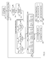
- FIG. 3A-3C schematic block diagrams of a system for detecting inter-circuit faults in a generator stator 12 ( FIG. 2 ) according to embodiments of the invention are shown.
- FIGS. 4-6 show flow diagrams of a method for detecting inter-circuit faults using the system(s) shown in FIGS. 1-3C . It should be apparent to one skilled in the art that embodiments can be rendered in a hardware implementation, a software implementation, and/or a combination of hardware and software.
- input voltages 40 (V a , V b , V c ) for each phase can be acquired, such as by using one or more voltmeters in winding 1 ( FIG. 1 ) or by any other suitable technique known in the art.
- input currents 42 (I a , I b I c ) for each phase can be acquired, such as by using one or more ammeters in winding 1 ( FIG. 1 ) or by any other suitable technique known in the art.
- phase voltage(s) and/or phase current(s) may be referred to as “sampling” phase voltage(s) and/or phase current(s) using a “sampler,” by which is meant that one or more sample values of each property is acquired, such as by using a voltmeter for voltage or an ammeter for current, and such as by taking measurements periodically at a “sample rate” so that a plurality of values are measured over time.
- various blocks serve to prevent (“block”) the use of IC-FD unless other types of faults have been ruled out, voltage levels are within predefined ranges in which IC-FD is desired, and a negative sequence is not present, some of which can be based on sampled phase currents, sampled phase voltages, and/or processed sampled phase voltages.
- one or more root mean square (RMS) devices 33 can receive input/sampled phase voltages 40 and can process measured values to obtain RMS values for each phase voltage.
- RMS root mean square
- each RMS device 33 can take the form of a true RMS converter that receives an AC voltage signal and outputs a DC voltage signal equal to the RMS voltage of the AC voltage received, or a circuit can be implemented to calculate the RMS voltage in another well-known fashion.
- a plurality of predefined blocks 29 can include a directional element 52 based on input currents 42 , a ground fault desensitizer 54 receiving RMS phase voltage values from RMS device(s) 33 , a phase-phase fault de-sensitizer 56 receiving RMS phase voltage values from RMS device(s) 33 , and/or an operator block 58 with which an operator can prevent IC-FD from being used.
- the plurality of predefined blocks 29 can be implemented using known techniques as suggested above, and the outputs of the blocks can have binary values, i.e. 0 or 1, sent to a multiplier 291 .
- Multiplier 291 can output a 0 or 1 that can be used as an enabling signal, such as to be used in a level detection block 34 to effectively enable IC-FD comparison logic 70 as will be described. Output of multiplier 291 can thus have a value of 1 only when all blocks output a value of 1 and will have a value of 0 if even one of the blocks output a value of 0.
- Level detection block 34 in addition to receiving output of multiplier 291 , can receive RMS phase voltage values from RMS device(s) 33 , which can be used in level detection 36 and unbalance desensitizer 38 to determine a plurality of voltage differences X, Y, Z in element 341 .
- RMS phase voltage values from RMS device(s) 33 , which can be used in level detection 36 and unbalance desensitizer 38 to determine a plurality of voltage differences X, Y, Z in element 341 .
- one or more adder-subtractors or subtractors can be used to determine the voltage differences as is known in the art.
- element 341 can be configured to receive processed RMS phase voltage values from level detection 36 and determine differences/error signals X, Y, Z. These differences X, Y, Z can each be multiplied in a multiplier 342 by the output of multiplier 291 so that the values of differences X, Y, Z are sent to comparison logic 70 only when the output of multiplier 291 has a value of 1, in which case comparison logic 70 is enabled.
- a negative sequence block 35 can receive input voltages 40 directly rather than via RMS device 33 in embodiments and can be processed to obtain a negative sequence voltage (V_ 2 ).
- Negative sequence voltage (V_ 2 ) can be compared with a user settable threshold to detect an over voltage condition ( 59 _ 2 ), and can be used to detect loss of one or two phases, or a non-symmetrical voltage condition, that corresponds to an inter-circuit fault condition.
- Negative sequence block 35 can employ known techniques, such as those indicated in FIG. 3A , and threshold values, user-settable or predefined, to determine when a negative sequence is present that should result in a trip of a breaker or other interrupt 99 .
- Comparison logic 70 can include an A-phase branch 72 , a B-phase branch 74 , and a C-phase branch 76 that apply various comparisons of the error signals X, Y, Z to produce a binary/logical value for each phase to represent detection of an IC-F.
- Output of the branches 72 , 74 , 76 can be fed to an OR gate 80 such that detection of an IC-F in one branch results in an IF-FD trip signal 50 , which can result in activation of interrupt 99 .
- (7) Y
- , and (8) Z
- this implementation can include input voltages 40 , input currents 42 , predefined blocks 29 , comparison logic 70 , IC-FD trip signal 50 , and interrupt 99 as in FIG. 3A .
- the implementation of FIG. 3B can include an input module 39 receiving input voltages 40 via input terminals or the like 361 connected to respective RMS devices 33 that each output a RMS voltage value for a respective phase.
- Outputs of RMS devices 33 can be connected to difference devices 362 , such as adder-subtractors or subtractors, so that, for example, differences (V a ⁇ V b ), (V b ⁇ V c ), and (V c ⁇ V a ) can be determined and output to level detection 34 .
- V a ⁇ V b
- , and Z
- Absolute value determining element 344 can be any known and/or suitable circuit or device that can determine absolute value, which should easily be within the ken of one of ordinary skill in the art. Inasmuch as circuits to determine the absolute value of a difference between two input voltages are well known in the art, such a device could be employed in place of difference device(s) 362 and element(s) 344 could be eliminated.
- Error signals X, Y, Z can be sent to comparison logic 70 directly, but as shown can also first be sent to a respective multiplier 346 in two paths, one of which passes through a respective relay 345 .
- Each relay 345 can allow introduction of a threshold value or the like, such as by an operator, below which its output can be 0 so that the value of the respective voltage difference/error signal X, Y, Z 347 will be rendered 0 by respective multiplier 346 .
- the use of relays 345 can thus constitute a load unbalance desensitizer, typically using a ⁇ 10% unbalance limit that can be set, such as by an operator, to allow phase loading unbalance.
- FIG. 3C an implementation of embodiments is shown with an example of an implementation of comparison logic 70 .
- voltages 40 and currents 42 of a generator 1 such as phases A, B, C of stator 12 above ( FIG. 2 ) can be measured/sampled and provided to a plurality of predefined blocks 29 and level detection block 34 .
- the particular implementations of these elements can be as in FIG. 3A or FIG. 3B or another implementation, so long as suitable input voltages 40 can be provided to level detection block 34 to produce error signals X, Y, Z 347 , which can be selectively enabled using an output value of predefined blocks 29 .
- input currents 42 are used only when a directional element block 52 is present in plurality of blocks 29 , and that level detection block 34 and comparison logic 70 only need input voltages 40 for IC-FD program/scheme/system 30 .
- comparison logic 70 can include a plurality of comparators 701 - 712 receiving various combinations of error signals X, Y, Z and outputting logical results to a plurality of OR gates 713 - 722 .
- comparators 701 - 704 can receive both error signal X and error signal Y such that comparator 701 can output a logical high (1) when error signal X is greater than or equal to error signal Y, comparator 702 can output a logical high (1) when error signal Y is greater than or equal to error signal X, comparator 703 can output a logical high (1) when error signal X is greater than error signal Y, and comparator 704 can output a logical high (1) when error signal Y is greater than rror signal X.
- comparators 705 - 708 can receive both error signal Y and error signal Z such that comparator 705 can output a logical high (1) when error signal Y is greater than or equal to error signal Z, comparator 706 can output a logical high (1) when error signal Z is greater than or equal to error signal Y, comparator 707 can output a logical high (1) when error signal Y is greater than error signal Z, and comparator 708 can output a logical high (1) when error signal Z is greater than error signal Y.
- comparators 709 - 712 can receive both error signal X and error signal Z such that comparator 709 can output a logical high (1) when error signal X is greater than error signal Z, comparator 710 can output a logical high (1) when error signal Z is greater than error signal X, comparator 711 can output a logical high (1) when error signal X is greater than or equal to error signal Z, and comparator 712 can output a logical high (1) when error signal Z is greater than or equal to error signal Z.
- the outputs of comparators 701 and 702 can be sent to OR gate 713
- the outputs of comparators 703 and 704 can be sent to OR gate 714
- the outputs of comparators 705 and 706 can be sent to OR gate 715
- the outputs of comparators 707 and 708 can be sent to OR gate 716
- the outputs of comparators 709 and 710 can be sent to OR gate 717
- the outputs of comparators 711 and 712 can be sent to OR gate 718 .
- OR gates 714 , 716 , and 718 can be sent to an AND gate 719 of A-phase branch 72 , while the outputs of OR gates 713 , 716 , and 717 can be sent to an AND gate 720 of B-phase branch 74 , and the outputs of OR gates 714 , 717 , and 715 can be sent to an AND gate of C-phase branch 76 .
- A-phase branch 72 , B-phase branch 74 , and C-phase branch 76 can be sent to an OR gate 80 as in other embodiments, but can each include a delay 78 , such as a timer, so that transient detection of IC-F in a phase will not result in activation of IC-FD trip 50 and interruption of operation of generator 1 .
- Comparison logic 70 as shown in FIG. 3C can also be expressed as:
- a -Phase 72 IC-FD [ ⁇ ( X>Y ) OR ( Y>X ) ⁇ AND ⁇ ( Y>Z ) OR ( Z>Y ) ⁇ AND ⁇ ( X>Z ) OR ( Z>X ) ⁇ ] (10)
- B -Phase 74 IC-FD [ ⁇ ( X>Y ) OR ( Y>X ) ⁇ AND ⁇ ( Y>Z ) OR ( Z>Y ) ⁇ AND ⁇ ( X>Z ) OR ( Z>X ) ⁇ ] (11)
- C -Phase 76 IC-FD [ ⁇ ( X>Y ) OR ( Y>X ) ⁇ AND ⁇ ( Y>Z ) OR ( Z>Y ) ⁇ AND ⁇ ( X>Z ) OR ( Z>X ) ⁇ ] (12) where each of Eqs. (10)-(12) yields a logical high (1) when an IC-
- a sampler samples phase voltages 40 (V a , V b , V c ) for each phase of the generator stator 12 ( FIG. 2 ), which can yield input voltages 40 of FIGS. 3A-3C .
- the sampler samples phase currents 42 (I a , I b , I c ) for each phase of the generator stator 12 ( FIG. 2 ), which can yield input currents 42 of FIGS. 3A-3C .
- phase voltages 40 and phase currents 42 of generator stator 12 may be sampled using any now known or later developed sampling technique, though embodiments contemplate the use of voltmeters and/or ammeters to obtain values used as input voltages 40 and/or input currents 42 as described above.
- IC-FD program/system 30 can include a level detection block 34 , a comparison logic 70 , and a negative sequence block 35 .
- IC-FD program/system 30 can include an “OR” gate 80 receiving outputs of respective phase-specific branches 72 , 74 , 76 of comparison logic 70 .
- the plurality of pre-defined blocks 29 enable the IC-FD program 30 only in particular situations, based on the sampled phase voltages 40 and phase currents 42 .
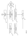
- the direction of the fault is sensed using directional element 52 . That is, directional element 52 determines whether the fault is inside or outside of the generator. If the fault is not within the generator (“N”), then the directional element 52 continues to determine, at D 1 , whether there is a fault inside the generator. Once the directional element 52 determines that a fault is within the generator (“Y”), at D 2 , a ground fault de-sensitizer 54 determines, based on the sampled phase voltages 40 , whether the fault is a ground fault.
- the parameter threshold to determine whether a fault is a ground fault may be set by a user. For example, if a sampled phase voltage 40 is less than or equal to approximately twenty percent (20%) rated, then the fault may be considered by the pre-defined blocks 29 as a ground fault (“Y”). In this case, the ground fault de-sensitizer 54 , at D 2 , will continue to determine if a ground fault exists.
- ground fault de-sensitizer 54 determines that a ground fault does not exist (“N”)
- a phase-phase fault de-sensitizer 56 determines, at D 3 , based on the sampled phase voltages 40 , whether the fault is a phase-phase fault.
- the parameter threshold for determining whether a fault is a phase-phase fault may be set by a user. For example, if any two of the sampled phase voltages 40 is less than approximately sixty percent (60%) rated, then the fault may be considered a phase-phase fault. It is only if the fault is not a phase-phase fault (“N”), that the IC-FD program/system 30 is enabled (S 3 ).
- the pre-defined blocks prevent IC-FD program/system 30 from being enabled unless the fault is within the generator stator 12 ( FIG. 2 ), the fault is not a ground fault, and the fault is not a phase-phase fault.
- Pre-defined block 29 can also be provided with an operator block 58 , to prevent IC-FD program/system 30 , from being enabled.
- Operator block 58 is a user configurable block that, when selected, will prevent IC-FD program 30 from being enabled.
- the operator block 58 along with pre-defined blocks, directional element 52 , ground fault de-sensitizer 54 , and phase-phase fault de-sensitizer 56 , collectively prevent IC-FD program 30 from being enabled.
- the level detection 36 of the level detection block 34 determines, at S 4 , the differences between each of the sampled phase root mean square (RMS) voltages 40 .
- the sampled voltages 40 go through the RMS block 33 prior to the level detection block 34 .
- error signals X, Y, Z can be determined per Eqs. (1)-(3) and/or Eqs. (7)-(9) above.
- X is the difference between sampled phase RMS voltage V a and sampled phase RMS voltage V b .
- Y is the difference between sampled phase RMS voltage V b and sampled phase RMS voltage V c .
- Level detection block 34 also includes an unbalance de-sensitizer 38 that does not allow the comparison logic 70 , to run when the unbalance in sampled phase voltages V a , V b , V c are within user settable limits. For example, at D 4 , only if the unbalance is not within a pre-defined, user set, limit (“N”), that the comparison logic 70 (S 5 ) is run. Typically, a ⁇ 10% unbalance limit can be set to allow phase loading unbalance.
- Unbalance de-sensitizer 38 may include a plurality of relays, such as relays 345 shown in the implementation of FIG. 3B .
- comparison logic 70 determines whether an inter-circuit fault is within at least one phase of the generator stator 12 ( FIG. 2 ). That is, A-phase 72 would be logic high “1” if an inter-circuit fault is within the T 1 -T 4 phase 2 (sampled phase RMS voltage V a ).
- an A-phase memory flag to register an A-phase inter-circuit fault event can beset high.
- B-phase 74 would be logic high “1” if an inter-circuit fault is within the T 2 -T 5 phase 4 (sampled phase RMS voltage V b ).
- B-Phase 74 logic high is reached, a B-phase memory flag to register a B-phase inter-circuit fault event can be set high.
- C-phase 76 would be logic high “1” if an inter-circuit fault is within the T 3 -T 6 phase 6 (sampled phase RMS voltage V c ).
- Comparison logic 70 may also include delay 78 (i.e., timer blocks) for each phase 72 , 74 , 76 to ensure isolation of the generator under a sustained inter-circuit fault as opposed to a transient indication of IC-F, which can eliminate tripping an interrupt due to a false positive determination of IC-F.
- delay 78 i.e., timer blocks
- a parallel negative sequence over-voltage ( 59 _ 2 ) block 35 is provided.
- the negative sequence block 35 receives the sampled voltages 40 .
- Negative sequence block 35 accepts sampled phase voltages 40 through star or delta voltage transformer connections. Sampled phase voltages 40 are processed in negative sequence block 35 in order to obtain a negative sequence voltage (V_ 2 ).
- Negative sequence voltage (V_ 2 ) is compared with a user settable threshold to detect over voltage condition ( 59 _ 2 ).
- Negative sequence over-voltage detection through negative sequence block 35 is used to detect loss of one or two phases, or a non-symmetrical voltage condition, that corresponds to an inter-circuit fault condition.
- the negative sequence voltages are determined.
- an IC-FD signal is generated. If an inter-circuit fault is detected in any of the phases through a combination of level detection 34 and comparison logic 70 , or negative sequence block 35 , at S 8 an IC-FD trip 50 is generated, which could be used for isolating and de-energizing the generating unit.
- predefined blocks 29 can advantageously be performed/can operate substantially simultaneously, such as shown in FIG. 6 . More specifically, IC-FD capable system can start at S 61 , can read/measure terminal phase voltage at S 62 , can determine whether detection is enabled at D 61 , and whether user block is enabled at D 62 . If detection is enabled and user block is not enabled, then the predefined blocks 29 can operate in parallel (D 63 -D 65 ) to determine whether non-inter-circuit faults have occurred or other conditions are present that should prevent IC-FD from proceeding.
- relay settable parameters S 63 -S 65 can be employed, and on relay pick-up for any phase, IC-FD comparison logic 70 can be engaged, and if an IC-F is detected, after a delay has elapsed at S 66 , decision support system S 67 can interrupt operation of the generator at S 68 and/or use the human-machine interface to notify an operator or control system of the fault at S 69 .
- an inter-circuit fault detection analysis could be enabled when ground fault desensitizer 54 receives input voltages 40 that are more than 20% of rated RMS voltage value, when phase unbalance desensitizer 36 (or relays 345 ) receives input voltages 40 that are more than 90% of rated RMS voltage value, and phase-phase fault desensitizer 56 determines that no two phases are less than 60% of rated RMS voltage value.
- a B-phase fault is indicated when Y>Z or Z>Y, meaning that
- the invention provides a computer program fixed in at least one computer-readable medium, which when executed, enables a computer system to detect inter-circuit faults in a generator stator 12 ( FIG. 2 ).
- the computer-readable medium includes program code, such as pre-defined blocks 29 and/or IC-FD program 30 ( FIG. 2 ), which implements some or all of a process described herein.
- computer-readable medium comprises one or more of any type of tangible medium of expression, now known or later developed, from which a copy of the program code can be perceived, reproduced, or otherwise communicated by a computing device.
- the computer-readable medium can comprise: one or more portable storage articles of manufacture; one or more memory/storage components of a computing device; paper; and/or the like.
Landscapes
- Physics & Mathematics (AREA)
- General Physics & Mathematics (AREA)
- Tests Of Circuit Breakers, Generators, And Electric Motors (AREA)
Abstract
Description
X=f(V a −V b), (1)
Y=f(V b −V c), (2)
Z=f(V c −V a). (3)
A-Phase 72 IC-FD=f 1{(X,Y) AND (Y,Z) AND (X,Z)}, (4)
B-
C-
X=|V a −V b| (7)
Y=|V b −V c|, and (8)
Z=|V c −V a|. (9)
A-Phase 72 IC-FD=[{(X>Y) OR (Y>X)} AND {(Y>Z) OR (Z>Y)} AND {(X>Z) OR (Z>X)}] (10)
B-
C-
where each of Eqs. (10)-(12) yields a logical high (1) when an IC-F is detected. It should be recognized that Eqs. (10)-(12) are a particular implementation of
Claims (20)
Priority Applications (1)
| Application Number | Priority Date | Filing Date | Title |
|---|---|---|---|
| US15/335,073 US10310017B2 (en) | 2012-09-13 | 2016-10-26 | Detection of generator stator inter-circuit faults |
Applications Claiming Priority (2)
| Application Number | Priority Date | Filing Date | Title |
|---|---|---|---|
| US13/613,721 US20140074413A1 (en) | 2012-09-13 | 2012-09-13 | Detection of generator stator inter-circuit faults |
| US15/335,073 US10310017B2 (en) | 2012-09-13 | 2016-10-26 | Detection of generator stator inter-circuit faults |
Related Parent Applications (1)
| Application Number | Title | Priority Date | Filing Date |
|---|---|---|---|
| US13/613,721 Continuation-In-Part US20140074413A1 (en) | 2012-09-13 | 2012-09-13 | Detection of generator stator inter-circuit faults |
Publications (2)
| Publication Number | Publication Date |
|---|---|
| US20170074941A1 US20170074941A1 (en) | 2017-03-16 |
| US10310017B2 true US10310017B2 (en) | 2019-06-04 |
Family
ID=58237602
Family Applications (1)
| Application Number | Title | Priority Date | Filing Date |
|---|---|---|---|
| US15/335,073 Active 2033-08-31 US10310017B2 (en) | 2012-09-13 | 2016-10-26 | Detection of generator stator inter-circuit faults |
Country Status (1)
| Country | Link |
|---|---|
| US (1) | US10310017B2 (en) |
Families Citing this family (2)
| Publication number | Priority date | Publication date | Assignee | Title |
|---|---|---|---|---|
| CN112964987B (en) * | 2021-03-19 | 2025-01-07 | 牛玉涛 | A portable platform door system motor state detection device and method |
| CN114415026B (en) * | 2022-03-28 | 2022-06-24 | 爱科赛智能科技(浙江)有限公司 | Motor fault diagnosis system and method based on current and phase recognition |
Citations (18)
| Publication number | Priority date | Publication date | Assignee | Title |
|---|---|---|---|---|
| US4795983A (en) | 1988-03-07 | 1989-01-03 | Westinghouse Electric Corp. | Method and apparatus for identifying a faulted phase |
| US4964058A (en) | 1988-10-13 | 1990-10-16 | Square D Company | Power management and automation system |
| US5514978A (en) | 1995-03-20 | 1996-05-07 | General Electric Company | Stator turn fault detector for AC motor |
| US5608327A (en) | 1994-04-25 | 1997-03-04 | Gec Alsthom Limited | Methods and apparatus for identifying faulted phases on an electric power transmission line |
| US5929549A (en) * | 1998-04-02 | 1999-07-27 | Pacific Scientific Company | Fault tolerant electric machine |
| US6020711A (en) * | 1998-03-05 | 2000-02-01 | The United States Of America As Represented By The Secretary Of The Air Force | Multiple winding channel, magnetic coupling-alterable reluctance electrical machines and their fault tolerant control |
| US6611771B1 (en) | 2000-10-04 | 2003-08-26 | Eaton Corporation | Method and apparatus to detect a stator turn fault in an AC motor |
| CN1560976A (en) | 2004-03-05 | 2005-01-05 | 清华大学 | Protection and Fault Location Method for Single-phase Grounding of Generator Stator Winding |
| US20070085549A1 (en) | 2005-06-01 | 2007-04-19 | Schweitzer Engineering Laboratories Inc. | Apparatus and method for determining a faulted phase of a three-phase ungrounded power system |
| US20080042683A1 (en) * | 2006-03-31 | 2008-02-21 | Kasztenny Bogdan Z | Methods and system for detecting winding faults in a generator with parallel windings |
| US20080284391A1 (en) | 2006-12-29 | 2008-11-20 | Texas Instruments Incorporated | Fault protection circuit, method of operating a fault protection circuit and a voltage regulator employing the same |
| US20090091289A1 (en) | 2007-10-08 | 2009-04-09 | University Of Victoria Innovation And Development Corporation | Stator inter-turn fault detection of synchronous machines |
| US7663849B2 (en) | 2006-08-17 | 2010-02-16 | Hamilton Sundstrand Corporation | Permanent magnet generator protection scheme |
| CN101702512A (en) | 2009-11-20 | 2010-05-05 | 清华大学 | Negative sequence impedance direction protection method for interior failures of stator winding of steamer generator |
| US20100194323A1 (en) | 2009-02-03 | 2010-08-05 | General Electric Company | Robust on line stator turn fault identification system |
| US7834573B2 (en) | 2007-07-31 | 2010-11-16 | Caterpillar Inc | Winding fault detection system |
| US20110085272A1 (en) | 2009-10-13 | 2011-04-14 | Schweitzer Iii Edmund O | Systems and Methods for Generator Ground Fault Protection |
| US8823307B2 (en) * | 2011-07-04 | 2014-09-02 | Abb Research Ltd. | System for detecting internal winding faults of a synchronous generator, computer program product and method |
-
2016
- 2016-10-26 US US15/335,073 patent/US10310017B2/en active Active
Patent Citations (18)
| Publication number | Priority date | Publication date | Assignee | Title |
|---|---|---|---|---|
| US4795983A (en) | 1988-03-07 | 1989-01-03 | Westinghouse Electric Corp. | Method and apparatus for identifying a faulted phase |
| US4964058A (en) | 1988-10-13 | 1990-10-16 | Square D Company | Power management and automation system |
| US5608327A (en) | 1994-04-25 | 1997-03-04 | Gec Alsthom Limited | Methods and apparatus for identifying faulted phases on an electric power transmission line |
| US5514978A (en) | 1995-03-20 | 1996-05-07 | General Electric Company | Stator turn fault detector for AC motor |
| US6020711A (en) * | 1998-03-05 | 2000-02-01 | The United States Of America As Represented By The Secretary Of The Air Force | Multiple winding channel, magnetic coupling-alterable reluctance electrical machines and their fault tolerant control |
| US5929549A (en) * | 1998-04-02 | 1999-07-27 | Pacific Scientific Company | Fault tolerant electric machine |
| US6611771B1 (en) | 2000-10-04 | 2003-08-26 | Eaton Corporation | Method and apparatus to detect a stator turn fault in an AC motor |
| CN1560976A (en) | 2004-03-05 | 2005-01-05 | 清华大学 | Protection and Fault Location Method for Single-phase Grounding of Generator Stator Winding |
| US20070085549A1 (en) | 2005-06-01 | 2007-04-19 | Schweitzer Engineering Laboratories Inc. | Apparatus and method for determining a faulted phase of a three-phase ungrounded power system |
| US20080042683A1 (en) * | 2006-03-31 | 2008-02-21 | Kasztenny Bogdan Z | Methods and system for detecting winding faults in a generator with parallel windings |
| US7663849B2 (en) | 2006-08-17 | 2010-02-16 | Hamilton Sundstrand Corporation | Permanent magnet generator protection scheme |
| US20080284391A1 (en) | 2006-12-29 | 2008-11-20 | Texas Instruments Incorporated | Fault protection circuit, method of operating a fault protection circuit and a voltage regulator employing the same |
| US7834573B2 (en) | 2007-07-31 | 2010-11-16 | Caterpillar Inc | Winding fault detection system |
| US20090091289A1 (en) | 2007-10-08 | 2009-04-09 | University Of Victoria Innovation And Development Corporation | Stator inter-turn fault detection of synchronous machines |
| US20100194323A1 (en) | 2009-02-03 | 2010-08-05 | General Electric Company | Robust on line stator turn fault identification system |
| US20110085272A1 (en) | 2009-10-13 | 2011-04-14 | Schweitzer Iii Edmund O | Systems and Methods for Generator Ground Fault Protection |
| CN101702512A (en) | 2009-11-20 | 2010-05-05 | 清华大学 | Negative sequence impedance direction protection method for interior failures of stator winding of steamer generator |
| US8823307B2 (en) * | 2011-07-04 | 2014-09-02 | Abb Research Ltd. | System for detecting internal winding faults of a synchronous generator, computer program product and method |
Non-Patent Citations (4)
| Title |
|---|
| Khorashadi-Zadeh "Application of Fuzzy Neuro for Generator Stator Earth Fault Detection" 7th Seminar on Neral Network Applications in Electrical Engineering. Sep. 23-25, 2004 pp. 127-130, IEEE 2004. |
| Luo et al., "Multiple Coupled Circuit Modeling of Induction Machines", IEEE Transactions on Industry Applications, vol. 31, No. 2, pp. 311-318 (Year: 1995). * |
| Pillai Grounding and Ground Faul Protection of Multiple Generator Installations on Medium-Voltage Industrial and Commercial Power System-part 3: Protection Methods, 4 pages IEEE 2003. |
| Pillai Grounding and Ground Faul Protection of Multiple Generator Installations on Medium-Voltage Industrial and Commercial Power System—part 3: Protection Methods, 4 pages IEEE 2003. |
Also Published As
| Publication number | Publication date |
|---|---|
| US20170074941A1 (en) | 2017-03-16 |
Similar Documents
| Publication | Publication Date | Title |
|---|---|---|
| RU2540851C2 (en) | Method for selection of short-circuited phase and determination of short circuit type | |
| RU2557017C2 (en) | Fault identification and directional detection in three-phase power system | |
| EP2730023B1 (en) | System for detecting internal winding faults of a synchronous generator, computer program product and method | |
| US10333291B2 (en) | Multiple generator ground fault detection | |
| CN103576045B (en) | By the sensitive middle crimping earth fault of linear correlation angle detecting | |
| US20160299187A1 (en) | Wide area fault detection method using pmu data | |
| JP6894443B2 (en) | Systems and methods for determining fault locations in three-phase series-compensated transmission lines | |
| US10931097B2 (en) | Generator stator ground protection using third harmonic | |
| CN102818969B (en) | Detection location equipment, the method and system of the resistive ground failure of medium voltage network | |
| US20180306853A1 (en) | Method and system for locating ground faults in a network of drives | |
| JP6503322B2 (en) | Ground fault detection device | |
| US10782356B2 (en) | Systems and methods for monitoring leakage current of an industrial machine | |
| CN106257294A (en) | For the method and apparatus detecting the fault in electrical network | |
| JP2011137718A (en) | Device for monitoring high voltage insulation | |
| US10310017B2 (en) | Detection of generator stator inter-circuit faults | |
| US20140074413A1 (en) | Detection of generator stator inter-circuit faults | |
| KR102006186B1 (en) | Digital protective relay | |
| JP7854060B2 (en) | Phase selection method | |
| CN118068227A (en) | Method, device and storage medium for judging single-phase grounding fault on low-voltage side of main transformer | |
| CN118914922A (en) | Method and device for identifying broken neutral line of current secondary loop | |
| CN120559531A (en) | Single-phase disconnection detection method, device and system | |
| CN115764822A (en) | DC microgrid protection method, system, equipment and medium based on high frequency components | |
| Olejnik | Alternative method of determining zero-sequence voltage for fault current passage indicators in overhead medium voltage networks | |
| CN224035499U (en) | A composite current detection sensor | |
| Liang et al. | Processing synchrophasor data using a feature selection procedure |
Legal Events
| Date | Code | Title | Description |
|---|---|---|---|
| AS | Assignment |
Owner name: GENERAL ELECTRIC COMPANY, NEW YORK Free format text: ASSIGNMENT OF ASSIGNORS INTEREST;ASSIGNORS:SOM, SHANTANU;BUKHALA, ZEEKY ASHIONO;SIGNING DATES FROM 20161027 TO 20161129;REEL/FRAME:040496/0190 |
|
| STPP | Information on status: patent application and granting procedure in general |
Free format text: NOTICE OF ALLOWANCE MAILED -- APPLICATION RECEIVED IN OFFICE OF PUBLICATIONS |
|
| STPP | Information on status: patent application and granting procedure in general |
Free format text: PUBLICATIONS -- ISSUE FEE PAYMENT VERIFIED |
|
| STCF | Information on status: patent grant |
Free format text: PATENTED CASE |
|
| MAFP | Maintenance fee payment |
Free format text: PAYMENT OF MAINTENANCE FEE, 4TH YEAR, LARGE ENTITY (ORIGINAL EVENT CODE: M1551); ENTITY STATUS OF PATENT OWNER: LARGE ENTITY Year of fee payment: 4 |
|
| AS | Assignment |
Owner name: GE INFRASTRUCTURE TECHNOLOGY LLC, SOUTH CAROLINA Free format text: ASSIGNMENT OF ASSIGNORS INTEREST;ASSIGNOR:GENERAL ELECTRIC COMPANY;REEL/FRAME:065727/0001 Effective date: 20231110 |