US103092A - Improvement in horse hay-rakes - Google Patents
Improvement in horse hay-rakes Download PDFInfo
- Publication number
- US103092A US103092A US103092DA US103092A US 103092 A US103092 A US 103092A US 103092D A US103092D A US 103092DA US 103092 A US103092 A US 103092A
- Authority
- US
- United States
- Prior art keywords
- improvement
- rakes
- wheel
- rake
- horse hay
- Prior art date
- Legal status (The legal status is an assumption and is not a legal conclusion. Google has not performed a legal analysis and makes no representation as to the accuracy of the status listed.)
- Expired - Lifetime
Links
- 238000010276 construction Methods 0.000 description 1
- 230000003028 elevating effect Effects 0.000 description 1
- 230000035939 shock Effects 0.000 description 1
Images
Classifications
-
- A—HUMAN NECESSITIES
- A01—AGRICULTURE; FORESTRY; ANIMAL HUSBANDRY; HUNTING; TRAPPING; FISHING
- A01D—HARVESTING; MOWING
- A01D76/00—Haymakers with tines that are stationary with respect to the machine during operation but that may be liftable for dumping
- A01D76/006—Hay-sweeps
Definitions
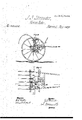
- FIG. 3 is a vertical transverse section oi' the same taken on the plane oi' the line y y, Fig. et, Fie. 4 is ⁇ a detail plan or top view of the same.
- This invention relates to mechanism for intermittently elevating and emptying a hayrake; ⁇ and consists in an improvement therein claims.
- a in the drawing represents the frame of ⁇ my improved horse hay-rake, containing ⁇ bearings ior the axles B U ot' the drivingwheels D and E, the two axles being in line, as clearly shown in Fig. 1.
- Lhe inner ends ofthe axles B Oearry small bevel-gear wheels a and b, respectively, which mesh both into one intermediate bevel-whecl, c, which is hung in a larger toothed wheel, F, as
- the wheel F forms the connecting-link of, and is ⁇ hung upou'thc inner ends ot', the axles B C, ⁇ and can turn loose upon the y the machine is moved, and as the wheels B C same.
- a vertical. iframe, G in which is hung a pinion, d, the a e of which carries a crank, j', as shown in if l.
- Ihe rake-head I is hung in ihe irainc A., and carries 'the teeth J, of suitable construction, and a crossbar, L,through which the teeth pass linearly,
- the cross-bnr Li receives the back end oi the chain H, the said chain passing over ment, g, that is mounted upon the ral NVhcn, by means of a foot-lever, a, to its upper end, the frame G is swm A to carry the pinion d in contact the wheel F, the crank will be revolved so to pull the chain, which will swing the rake up to dump it.
- a wiring-catch, M locks ever on edge on the traine Gr, and locks the pinion (l, in gear while the rake is being dumped. .But after the said pinion has made about one rui-w olntion a cani, li, on its side strikes aw. clevates the catch M, and liberates the i' ie G. At the same time a larffe tooth on d wili mrow' the pinion ont o't gear, and will thrash; let the whole dumping apparatus ont ci fear.
- the chain H contains a rubber or other elastic piece or link, j, which causes the action of .dumping to be tree from all sudden or violent shocks or jars.
- the segment g is, by menus oi" a rod, l, conneeted with a cra-nk, m, on au arbor, n, which arbor carri is a hand-lever, N, by means of which the rake can be quickly raised ever desired.
- rIhe crank m has a 'oot f at its upper end, and constitutes., tes with the rod Z, a joint, which, when straightened, braces the .rake and holds the teeth. firmly down on the ground.
Landscapes
- Life Sciences & Earth Sciences (AREA)
- Environmental Sciences (AREA)
- Tires In General (AREA)
Description
` on,x`which will be specified JOHN S. SHRAWDER, OF FAIRVIEW VILLAGE, PENNSYLVANIA.
`IMPROVEMENT IN HORSE HAV=RAKES.
Specication forming part of Letters Patent No. Iiiibpf'i, dated May 17, 1870.
To all 'whom it may concern:
Beit known that '1, JOHN S. SHRAWDER, of Fairview Village, in the county of Monty. gomery and State 'of Pennsylvania, have iuvented a newand Improved Horse Hay Rake; and I do hereby declare that the following is a full, clear, and exact description thereof,
. which will enable others skilled in the art to `make and use the same, reference being had to the accompanying drawings, forming part oi' this speciiieation. v
Figurcl represents a vertical transverse the direction of the eye being inverted plan view of the saine. Fig. 3 is a vertical transverse section oi' the same taken on the plane oi' the line y y, Fig. et, Fie. 4 is `a detail plan or top view of the same.
Similar letters ot' reference indicate corresponding parts.
This invention relates to mechanism for intermittently elevating and emptying a hayrake;` and consists in an improvement therein claims. A in the drawing represents the frame of `my improved horse hay-rake, containing` bearings ior the axles B U ot' the drivingwheels D and E, the two axles being in line, as clearly shown in Fig. 1. Lhe inner ends ofthe axles B Oearry small bevel-gear wheels a and b, respectively, which mesh both into one intermediate bevel-whecl, c, which is hung in a larger toothed wheel, F, as
shown. The wheel F forms the connecting-link of, and is `hung upou'thc inner ends ot', the axles B C, `and can turn loose upon the y the machine is moved, and as the wheels B C same. Thus, as
with their axles are thereby revolved, they will rotate the wheel F.
Ii' botlrwheels D E turn with equal velocity,
`they will carry F around with the same speed without revolving the wheel c on its own axis; but it' one wheel, D or E, turns quicker than the other, its attachment a or b vwill also turn with greater rapidity, and will, by turning the wheel c, increase the speed of the Wheel F iu the saine ratio beyond the speed given to Ait by the slower wheel D or E, as the motion of the faster difiers 'from that ofthe slower wheel D E. rlhe wheel F, therefore, receives yalways the medium speed and the joint power of both wheels D E.
To the frame A is pivoted a vertical. iframe, G, in which is hung a pinion, d, the a e of which carries a crank, j', as shown in if l. The end of the crank fis, by means of a chain, H, connectmi with the rake. Ihe rake-head I is hung in ihe irainc A., and carries 'the teeth J, of suitable construction, and a crossbar, L,through which the teeth pass linearly, The cross-bnr Li receives the back end oi the chain H, the said chain passing over ment, g, that is mounted upon the ral NVhcn, by means of a foot-lever, a, to its upper end, the frame G is swm A to carry the pinion d in contact the wheel F, the crank will be revolved so to pull the chain, which will swing the rake up to dump it. a wiring-catch, M, locks ever on edge on the traine Gr, and locks the pinion (l, in gear while the rake is being dumped. .But after the said pinion has made about one rui-w olntion a cani, li, on its side strikes aw. clevates the catch M, and liberates the i' ie G. At the same time a larffe tooth on d wili mrow' the pinion ont o't gear, and will thrash; let the whole dumping apparatus ont ci fear. The chain H contains a rubber or other elastic piece or link, j, which causes the action of .dumping to be tree from all sudden or violent shocks or jars.
The segment g is, by menus oi" a rod, l, conneeted with a cra-nk, m, on au arbor, n, which arbor carri is a hand-lever, N, by means of which the rake can be quickly raised ever desired. rIhe crank m has a 'oot f at its upper end, and constitutes., tes with the rod Z, a joint, which, when straightened, braces the .rake and holds the teeth. firmly down on the ground.
Having thus described myinven'tion, .I claim as new and desire to secure by Letters Patentl. As an improvement in borse hay-rakes, a cam, h, and projecting tooth i, arranged on pinion d, as and i'or the purpose described. l
2. The arrangement oi' pinion d, provided. with cam it and tooth i, the gears F c c D, pivoted frame G, and springeatch M, all being constructed and operating as described.
JOHN S. SHRAWDER.
Witnesses:
D. M. CAssELBEnaY, ANN ELLZA GAssnLBnazeY.
Publications (1)
| Publication Number | Publication Date |
|---|---|
| US103092A true US103092A (en) | 1870-05-17 |
Family
ID=2172579
Family Applications (1)
| Application Number | Title | Priority Date | Filing Date |
|---|---|---|---|
| US103092D Expired - Lifetime US103092A (en) | Improvement in horse hay-rakes |
Country Status (1)
| Country | Link |
|---|---|
| US (1) | US103092A (en) |
-
0
- US US103092D patent/US103092A/en not_active Expired - Lifetime
Similar Documents
| Publication | Publication Date | Title |
|---|---|---|
| US103092A (en) | Improvement in horse hay-rakes | |
| US1166136A (en) | Side-delivery hay-rake. | |
| US948006A (en) | Shock and hay loader. | |
| US117204A (en) | Improvement in combined hay-rakes and loaders | |
| US30007A (en) | Improvement in horse-rakes | |
| US319274A (en) | Combined rake and tedder | |
| US68309A (en) | Nathan s | |
| US421891A (en) | banta | |
| US1299825A (en) | Beet-harvesting machine. | |
| US510730A (en) | Cotton-harvester | |
| US101189A (en) | Improvement in horse hay-rakes | |
| US145419A (en) | Improvement in harvester-droppers | |
| US24555A (en) | Improvement in raking attachments for harvesters | |
| US70870A (en) | Improvement in hoese-eakes and hay-spreadees combined | |
| US867025A (en) | Hay rake and tedder. | |
| US114065A (en) | Improvement in combined hay-rakes and tedders | |
| US64291A (en) | beardsley | |
| US1156734A (en) | Hay or shock loader. | |
| US365880A (en) | Potato-digger | |
| US956272A (en) | Potato-harvester. | |
| US216829A (en) | Improvement in horse hay-rakes | |
| USRE4232E (en) | Improvement in horse hay-rakes | |
| US113363A (en) | Improvement in hay-loaders | |
| US106611A (en) | Improvement in hay-loaders | |
| US209004A (en) | Improvement in horse hay-rakes |