US10309193B2 - Valve apparatus having dissolvable or frangible flapper and method of using same - Google Patents
Valve apparatus having dissolvable or frangible flapper and method of using same Download PDFInfo
- Publication number
- US10309193B2 US10309193B2 US15/424,109 US201715424109A US10309193B2 US 10309193 B2 US10309193 B2 US 10309193B2 US 201715424109 A US201715424109 A US 201715424109A US 10309193 B2 US10309193 B2 US 10309193B2
- Authority
- US
- United States
- Prior art keywords
- flapper
- valve assembly
- wellbore
- support member
- transverse support
- Prior art date
- Legal status (The legal status is an assumption and is not a legal conclusion. Google has not performed a legal analysis and makes no representation as to the accuracy of the status listed.)
- Active, expires
Links
- 238000000034 method Methods 0.000 title claims description 17
- 239000012530 fluid Substances 0.000 claims abstract description 54
- 239000000463 material Substances 0.000 claims abstract description 21
- 238000007789 sealing Methods 0.000 claims abstract description 19
- 230000004044 response Effects 0.000 claims description 5
- 238000012546 transfer Methods 0.000 claims description 3
- 238000004873 anchoring Methods 0.000 abstract description 5
- 238000012856 packing Methods 0.000 abstract description 3
- 230000013011 mating Effects 0.000 description 9
- 230000008569 process Effects 0.000 description 4
- 230000000712 assembly Effects 0.000 description 3
- 238000000429 assembly Methods 0.000 description 3
- 230000006835 compression Effects 0.000 description 3
- 238000007906 compression Methods 0.000 description 3
- 238000013461 design Methods 0.000 description 3
- 238000005086 pumping Methods 0.000 description 3
- 230000004888 barrier function Effects 0.000 description 2
- 230000015572 biosynthetic process Effects 0.000 description 2
- 238000005755 formation reaction Methods 0.000 description 2
- 238000003801 milling Methods 0.000 description 2
- 238000005096 rolling process Methods 0.000 description 2
- 230000000638 stimulation Effects 0.000 description 2
- XLYOFNOQVPJJNP-UHFFFAOYSA-N water Substances O XLYOFNOQVPJJNP-UHFFFAOYSA-N 0.000 description 2
- 229910000861 Mg alloy Inorganic materials 0.000 description 1
- 230000002411 adverse Effects 0.000 description 1
- 230000008901 benefit Effects 0.000 description 1
- 230000000903 blocking effect Effects 0.000 description 1
- 239000004568 cement Substances 0.000 description 1
- 150000001875 compounds Chemical class 0.000 description 1
- 238000007796 conventional method Methods 0.000 description 1
- 238000005260 corrosion Methods 0.000 description 1
- 230000007797 corrosion Effects 0.000 description 1
- 238000005553 drilling Methods 0.000 description 1
- -1 electronics Substances 0.000 description 1
- 239000002360 explosive Substances 0.000 description 1
- 238000002955 isolation Methods 0.000 description 1
- 238000004519 manufacturing process Methods 0.000 description 1
- 230000007246 mechanism Effects 0.000 description 1
- 239000011435 rock Substances 0.000 description 1
- 239000004576 sand Substances 0.000 description 1
- 239000003566 sealing material Substances 0.000 description 1
- 238000010008 shearing Methods 0.000 description 1
- 238000009987 spinning Methods 0.000 description 1
Images


Classifications
-
- E—FIXED CONSTRUCTIONS
- E21—EARTH OR ROCK DRILLING; MINING
- E21B—EARTH OR ROCK DRILLING; OBTAINING OIL, GAS, WATER, SOLUBLE OR MELTABLE MATERIALS OR A SLURRY OF MINERALS FROM WELLS
- E21B34/00—Valve arrangements for boreholes or wells
- E21B34/06—Valve arrangements for boreholes or wells in wells
- E21B34/063—Valve or closure with destructible element, e.g. frangible disc
-
- E—FIXED CONSTRUCTIONS
- E21—EARTH OR ROCK DRILLING; MINING
- E21B—EARTH OR ROCK DRILLING; OBTAINING OIL, GAS, WATER, SOLUBLE OR MELTABLE MATERIALS OR A SLURRY OF MINERALS FROM WELLS
- E21B33/00—Sealing or packing boreholes or wells
- E21B33/10—Sealing or packing boreholes or wells in the borehole
- E21B33/13—Methods or devices for cementing, for plugging holes, crevices or the like
- E21B33/134—Bridging plugs
-
- E21B2034/005—
-
- E—FIXED CONSTRUCTIONS
- E21—EARTH OR ROCK DRILLING; MINING
- E21B—EARTH OR ROCK DRILLING; OBTAINING OIL, GAS, WATER, SOLUBLE OR MELTABLE MATERIALS OR A SLURRY OF MINERALS FROM WELLS
- E21B2200/00—Special features related to earth drilling for obtaining oil, gas or water
- E21B2200/05—Flapper valves
Definitions
- the present invention pertains to a valve assembly that can be used in wellbore operations (such as, for example, in oil, gas, water or disposal wells). More particularly, the present invention pertains to a downhole valve assembly that can be used in wellbore operations, such as well intervention and/or hydraulic fracturing operations. More particularly still, the present invention pertains to a downhole flapper valve assembly having a dissolvable or frangible flapper.
- bridge plug or other anchoring and sealing device
- Such assemblies can be installed for various reasons: to isolate one portion of a wellbore from another, to prevent fluid flow from one portion of a wellbore to another, and/or provide a fluid pressure sealing barrier at a desired location within said wellbore.
- Such downhole bridge plugs or other anchoring/sealing devices are frequently installed within the central bore of a casing or tubing string, and both grip/anchor and provide a fluid pressure seal against the inner wall of such pipe.
- plugs can also be installed within a section of drilled “open hole” (that is, a section of a wellbore that is not cased with pipe).
- Conventional bridge plugs typically comprise an anchoring system designed to grip the inner surface of a surrounding wellbore, as well as a sealing system or packing element to form a fluid pressure seal against said inner surface. Some predetermined amount of force is generally required to energize/expand said packing element and actuate said anchoring system.
- such force or load can be supplied by pipe weight situated above the bridge plug, or by tensile loading applied from a wellbore surface; such plugs generally must be continually attached to a pipe string during the setting process in order to receive the force required to actuate said anchor system and energize/expand said sealing mechanism.
- such plug assemblies can be conveyed into a wellbore on spooled wireline to a desired location, and actuated using a specially designed plug setting tool.
- bridge plugs are frequently used in connection with hydraulic fracturing (commonly referred to as “fracking”) operations, which generally entails pumping fluid into a wellbore at elevated pressures in order to fracture subterranean rock formations surrounding said wellbore.
- frac plug In many well fracturing operations, a bridge plug or “frac plug” is conveyed to a desired location within a wellbore. Once positioned at a desired location within a wellbore, the frac plug is actuated to secure or anchor said plug in position and prevent axial movement within said wellbore. Thereafter, a setting tool or other device used to set said plug in place can then be removed, leaving the plug securely anchored within the well bore.
- frac plugs have a central axial through bore as well as sealing seat on one end.
- a ball, dart or other object is typically launched or released into the wellbore from the surface or other point above said plug; eventually, said ball/dart/object will reach the plug and land on said seat.
- said central through bore is blocked and fluid is prevented from flowing around said ball through said central through bore.
- hydraulic fracturing can be undertaken in up-hole section(s) of the well bore—that is, the portion of the well between the surface and said plug.
- plugs and valves are periodically used inside a well bore to control, stop or regulate certain well performance variables such as flowrate and pressure.
- the bridge plug should permit isolation of desired portion(s) of a wellbore, while permitting removal and/or opening of said plug when desired.
- present invention comprises a valve assembly.
- valve assembly can include, but are not limited to, a frac plug, fluid flow valve, check valve or well intervention device.
- the plug of the present invention can be used in bored holes, flow lines, sewer lines, open or closed well bores, agricultural applications, and medical procedures.
- the present invention comprises a selectively closable flapper and a seat against which said flapper, when in a closed configuration, can form a fluid pressure seal.
- the present invention further comprises means (such as gripping slip members) to securely grip against a surrounding surface, and create a fluid pressure seal between said valve assembly and said inner surface of a surrounding wellbore or other structure.
- the sealing member(s) may be elastomeric or any other material that can create a seal between the invention and the inner walls of a surrounding wellbore or hole.
- Actuation of said slip member(s) and seal(s) is typically accomplished using a conventional setting tool employing hydraulics, explosives, electronics, fluid pressure and/or the application of mechanical force.
- the present invention can also comprise at least one friction reducing element disposed on its outer surface to assist in running in a wellbore (including, without limitation, restrictions therein).
- friction reducing elements can be rolling devices such as ball transfer units or stationary sliding pads beneficially disposed on the exterior of the device.
- the present invention can also be used as a check valve by setting a flapper to spring closed if fluid flow is in the opposite direction than desired.
- the springs or other actuation methods on the present invention will make the device return to original (typically open) state once fluid pressure or flow has dissipated sufficiently to meet a predetermined level.
- the present invention can be used inside a well bore as a fluid flow control valve by controlling the flapper motion with a spring or other actuator.
- an actuator on the flapper can be sized to open and close in response to particular predetermined flow rates.
- Another benefit of the present invention is to reduce the amount of water pumped into downhole formations, which can adversely affect productivity of certain reservoirs.
- the present invention also allows a user, if desired, to perform other operations such as perforating an interval without the need to fully retrieve a toolstring or pipe completely out the well.
- the present invention facilitates increased efficiency of time, resources and money spent to perform current tasks common to industries such as the oilfield in particular in well hydraulic fracturing operations.
- the present invention can also be used as a check valve by setting a flapper to spring closed if fluid flow is in an opposite direction than desired.
- springs or other actuation methods on the present invention will make the device return to original (typically open) state once fluid pressure or flow has dissipated sufficiently to meet a predetermined level.
- the present invention can be used inside a well bore as a fluid flow control valve by controlling the flapper motion with a spring or other actuator.
- an actuator on the flapper can be sized to open and close in response to particular predetermined flow rates.
- the valve assembly becomes an obstruction that does not allow a well to flow past said valve assembly.
- fluid or pressure differential from below the invention can open the flapper, therefore allowing fluid or pressure movement.
- the flapper of the current invention includes a spring that biases said flapper after pumping from the surface stops to allow for the well to begin flowing.
- a standard oilfield fishing tool can be used to stab back into the body opening to retrieve the device from the well without milling or drilling.
- the flapper of the said invention can be in a normally opened or closed position. Applied or natural fluid pressure, or pressure differential, can open the flapper from the normally closed position or close the flapper from a normally opened position.
- FIG. 1 depicts an overhead perspective view of the downhole valve assembly of the present invention operationally attached to a conventional setting tool and disposed within a wellbore.
- FIG. 2 depicts a side view of a downhole valve assembly of the present invention operationally attached to a conventional setting tool.
- FIG. 3 depicts a side sectional view of a downhole valve assembly of the present invention operationally attached to a conventional setting tool.
- FIG. 4 depicts a side view of a downhole valve assembly of the present invention with a flapper valve in a closed position.
- FIG. 5 depicts an overhead perspective view of a downhole valve assembly of the present invention with a flapper valve in an open position.
- FIG. 8 depicts an overhead perspective view of the downhole valve assembly of the present invention disposed within a wellbore with a flapper valve in an open position.
- FIG. 9 depicts side view of the downhole valve assembly of the present invention disposed within a wellbore with a flapper valve in a closed position.
- FIG. 10 depicts a perspective view of a flapper of the present invention.
- FIG. 11 depicts a perspective view of a first alternative embodiment of a flapper assembly of the present invention.
- FIG. 13 depicts an overhead perspective view of a third alternative embodiment of a flapper assembly of the present invention.
- FIG. 1 depicts an overhead perspective view of a downhole valve assembly 100 of the present invention operationally attached to a conventional setting tool 20 and disposed within casing string 10 .
- casing string 10 has outer surface 12 and inner surface 11 ; said casing 10 can be installed and secured within a drilled bore hole in a manner well understood by those having skill in the art.
- Valve assembly 100 of the present invention generally comprises a fluid pressure sealing flapper assembly having flapper 110 , a mating flapper seat 111 , upper gripping slip members 120 , lower gripping slip members 130 , sealing member 140 and body section 150 .
- said upper gripping slip members 120 and lower gripping slip members 130 are typically disposed on either side of said seal member 140 .
- valve assembly 100 of the present invention can be attached to a setting tool (such as setting tool 20 ) and conveyed into a well to a desired depth via continuous wire (such as, for example, electric line, slick line or braided line), continuous or coiled tubing, or jointed pipe.
- a setting tool such as setting tool 20
- continuous wire such as, for example, electric line, slick line or braided line
- continuous or coiled tubing such as, for example, electric line, slick line or braided line
- jointed pipe jointed pipe.
- setting tool 20 can comprise a conventional wireline packer setting tool such as, for example, a Baker E4 Model 10 Setting Tool, which is well known to those having skill in the art. Notwithstanding the foregoing, it is to be observed that any number of other conventional setting tools can be used without departing from the scope of the present invention. As depicted in FIG. 1 , a central mandrel 21 of setting 20 is visible through the open lower bore 151 of body section 150 of valve assembly 100 .
- FIG. 2 depicts a side view of a downhole valve assembly 100 of the present invention operationally attached to a conventional setting tool 20 .
- Valve assembly 100 of the present invention generally comprises a fluid pressure sealing flapper assembly having flapper 110 and flapper seat 111 , upper gripping slip members 120 , lower gripping slip members 130 , seal member 140 and body section 150 .
- said seal member 140 is disposed between upper gripping slip members 120 and lower gripping slip members 130 .
- FIG. 3 depicts a side sectional view of a downhole valve assembly 100 of the present invention operationally attached to a conventional setting tool 20 .
- Valve assembly 100 of the present invention generally comprises a fluid pressure sealing flapper assembly having flapper 110 and flapper seat 111 .
- Flapper 110 is hingedly attached to flapper seat body 112 with hinge pin 113 extending through hinge posts 118 .
- Flapper seat body member 112 has outer surface 114 defining outer shoulder member 115 that extends radially outward therefrom, as well as a central through bore defining an inner surface 116 .
- upper gripping slip members 120 , lower gripping slip members 130 and seal member 140 are disposed on outer surface 114 of flapper seat body member 112 .
- Body section 150 having a central through bore 151 defining inner surface 154 , is attached to flapper seat body member 112 .
- central mandrel 21 of setting tool 20 extends through aligned central bores of flapper seat body member 112 and body section 150 . Said central mandrel 21 further holds flapper 110 in an open position; in other words, said central mandrel 21 prevents flapper 110 from hingedly closing and being received on flapper seat 111 .
- setting tool 20 can be actuated, causing upper gripping slip members 120 and lower gripping slip members 130 to expand radially outward to engage against a surrounding surface (such as inner surface 11 of casing string 10 depicted in FIG. 1 ).
- Such actuation of setting tool 20 also causes seal member 140 of said valve assembly 100 to expand radially outward until it contacts and forms a fluid pressure seal against a surrounding surface (such as inner surface 11 of casing string 10 depicted in FIG. 1 ).
- setting tool 20 can be released from valve assembly 100 (such as by shearing of pins, for example) and pulled away from said valve assembly 100 .
- flapper 110 is no longer blocked and is allowed to pivot about hinge pin 113 . Said flapper 110 can close until it contacts in mating relationship with flapper seat 111 .
- FIG. 4 depicts a side view of a downhole valve assembly 100 of the present invention with flapper valve 110 in a closed position
- FIG. 5 depicts an overhead perspective view of a downhole valve assembly 100 of the present invention with a flapper valve 110 in an open position
- a setting tool such as setting tool 20 depicted in FIGS. 1 through 3
- Valve assembly 100 of the present invention generally comprises a fluid pressure sealing flapper assembly having flapper 110 and flapper seat 111 , upper gripping slip members 120 , lower gripping slip members 130 , seal member 140 and body section 150 .
- Flapper 110 is hingedly attached to flapper seat body 112 with hinge pin 113 extending through parallel hinge posts 118 .
- Seal member 140 is disposed between upper gripping slip members 120 and lower gripping slip members 130 .
- flapper 110 is closed in mating relationship against flapper seat 111 .
- flapper 110 essentially obstructs the central flow bore of seat body member 112 , thereby forming a fluid pressure seal preventing fluid from flowing past said flapper and into said central flow bore of seat body member 112 .
- flapper 110 is open and is not in mating relationship against flapper seat 111 . In this configuration, flapper 110 does not obstruct the central flow bore 117 of seat body member 112 , thereby permitting fluid to flow past said flapper 110 and into said central flow bore 117 of seat body member 112 .
- the present invention can also comprise at least one friction reducing element 155 disposed on or along the outer surface of body member 150 to assist in reducing frictional forces when conveying said valve assembly 100 within a wellbore (including, without limitation, any restrictions or “tight spots” therein).
- friction reducing elements 155 can be rolling devices such as ball transfer units or stationary sliding pads beneficially disposed on the exterior of the device.
- At least one transverse shear pin 152 can extend through body member 150 ; said shear pin 152 can be used to temporarily operationally attach valve assembly 100 to a setting tool (such as, for example, setting tool 20 depicted in FIG. 1 ).
- notch 153 can be cut or otherwise formed in the lower surface 154 of said body member 150 .
- said valve assembly 100 may be pushed downhole within a wellbore until it is received on another valve assembly or other support surface.
- notch 153 can act as an anti-rotation device by receiving and engaging with upwardly facing parallel hinge posts (such as hinge posts 118 depicted in FIG. 4 ) of an adjacent (lower) valve assembly to prevent spinning or rotation of said upper valve assembly when torque forces are applied to said upper valve assembly (such as, for example, when said valve assembly is being drilled or milled).
- FIG. 6 depicts an overhead perspective view of down hole valve assembly 100 of the present invention disposed within the inner bore of casing string 10 with flapper 110 in a closed position.
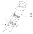
- FIG. 7 depicts a bottom perspective view of said downhole valve assembly 100 of the present invention disposed within an inner bore of casing string 10 with flapper 110 in a closed position.
- flapper 110 is closed in mating relationship against flapper seat 111 . In this configuration, flapper 110 obstructs or blocks the central flow bore of seat body member 112 , thereby forming a fluid pressure seal preventing fluid from flowing past said flapper and into said central flow bore of seat body member 112 .
- FIG. 8 depicts an overhead perspective view of downhole valve assembly 100 of the present invention disposed within an inner through bore of casing string 10 with flapper 110 in an open position
- FIG. 9 depicts side view of downhole valve assembly 100 of the present invention disposed within an inner through bore of casing 10 with flapper 110 in a closed position.
- flapper 110 is open and is not in mating relationship against flapper seat 111 . In this configuration, flapper 110 does not obstruct the central flow bore 117 of seat body member 112 , thereby permitting fluid to flow past said flapper 110 and into said central flow bore 117 of seat body member 112 .
- flapper 110 can embody a scalloped shaped design to allow for increased flow capacity when flapper 110 of valve assembly 100 is in a full open position, while also increasing strength against fluid pressure acting on said flapper 110 due to the curvature of said flapper 110 .
- mating flapper seat 111 can also be scalloped to match the contours and surfaces of flapper 110 to ensure that a tight fluid pressure seal is formed when said flapper 110 is closed in mating relationship against a flapper seat 111 .
- a sealing material such as an elastomeric or gasket material can be applied to, attached on and/or embedded in said flapper and/or said seat.
- Flapper 110 can be constructed of a dissolvable material. If such dissolvable material is used, after a predetermined or preselected length of time, the flapper will dissolve, thereby substantially eliminating any flow obstruction blocking central flow bore 117 of flapper seat body member 112 . Although other dissolvable materials having desired characteristics can be used without departing from the scope of the present invention, said flapper 110 can be constructed of magnesium alloy (such as, for example, the compound marketed under the mark “SoluMag”TM) having a high but well-controlled corrosion rate, thereby effectively causing flapper 110 to dissolve in a known time.
- magnesium alloy such as, for example, the compound marketed under the mark “SoluMag”TM
- said flapper 110 may also be constructed of a frangible material that can easily be broken into smaller pieces using a conventional device (such as, for example, an oilfield jar tool) to apply a predetermined contact force to said flapper. After contact with said breaking device, the pieces of flapper 110 are sufficiently small that they can fall to the bottom of the well, or can be circulated back to the surface for removal from a well. Flapper 110 can also be constructed of an easily drillable or millable material; for applications that do not require such removal of said flapper, a stronger, more durable material may be used.
- FIG. 10 depicts a perspective view of an alternative embodiment of a flapper 110 of the present invention.
- Flapper 110 can include hinge body protrusion 170 having transverse aperture 171 .
- Hinge body protrusion 170 can be received between hinge posts 118 , while transverse aperture 171 can receive a hinge pin (such as hinge pin 113 depicted in FIG. 3 ) to permit said flapper 110 to pivotally alternate between an open and closed position as disclosed herein.
- said flapper 110 can optionally include an increased or thicker body section 172 as depicted in FIG. 10 .
- body section 172 depicted in FIG. 10 is thicker (i.e., has a greater mass) compared to alternative flappers 110 depicted in FIGS. 11 and 12 , for example.
- seat 111 and tool body 112 can be modified to add support as depicted in FIGS. 12 and 13 .
- seat 111 includes a section 111 a of increased material around the circumference of bore 117 for receiving flapper 110 .
- seat 111 includes a transverse support 111 b extending substantially across bore 117 for receiving flapper 110 .
- FIGS. 12 and 13 reduce unsupported area under flapper 110 by adding a ring of support material around the opening of seat 111 ( FIG. 12 ) or across seat 111 ( FIG. 13 ) thereby allowing the valve assembly to withstand greater fluid pressure applied to the flapper 110 . If full bore flow is required, support can be made of dissolvable or frangible material and the aforementioned processes will be employed to remove them after pressure is relieved.
- FIG. 11 depicts a perspective view of an alternate embodiment of a flapper seat body member 212 , shown removed from valve assembly 100 of the present invention.
- flapper seat body member 212 can comprise a central through bore 217 .
- a flapper 210 is hingedly attached to said flapper seat body 212 , and a guide pin or protrusion 260 disposed on flapper seat 211 .
- Said guide pin 260 is used to align flapper 210 during actuation and to align the lower sleeve on a setting tool.
- Guide 260 can be formed as an integral part of flapper seat 211 or can be attached as an additional component.
- FIG. 14 depicts a perspective view of an alternative embodiment of the flapper mounting assembly present invention.
- a hinge post assembly 300 having parallel hinge posts 318 can be attached to body member 112 .
- Compression springs 301 can bias said hinge post assembly 300 away from said body member 112 .
- said compression springs 301 hold flapper 110 off of seat 111 , thereby allowing fluid to flow between the gap formed between said flapper 110 and seat 111 , until such time as fluid pressure overcomes the force of compression springs 301 , causing said gap to close and create a fluid pressure seal.
- Hydraulic fracturing or other operations can be performed within said wellbore.
- a frangible flapper can be selectively shattered into many small pieces by the application of contact force, such as via a conventional oilfield jar device. Such smaller shattered pieces can fall to the bottom of the wellbore, or can be circulated out of the wellbore.
- a dissolvable flapper can be permitted to dissolve within fluid(s) contained in said wellbore, thereby eliminating said fluid pressure seal between said flapper and seat.
Landscapes
- Life Sciences & Earth Sciences (AREA)
- Engineering & Computer Science (AREA)
- Geology (AREA)
- Mining & Mineral Resources (AREA)
- Physics & Mathematics (AREA)
- Environmental & Geological Engineering (AREA)
- Fluid Mechanics (AREA)
- General Life Sciences & Earth Sciences (AREA)
- Geochemistry & Mineralogy (AREA)
- Lift Valve (AREA)
Abstract
Description
Claims (20)
Priority Applications (2)
| Application Number | Priority Date | Filing Date | Title |
|---|---|---|---|
| US15/424,109 US10309193B2 (en) | 2016-02-03 | 2017-02-03 | Valve apparatus having dissolvable or frangible flapper and method of using same |
| US16/404,139 US20190264534A1 (en) | 2016-02-03 | 2019-05-06 | Valve Apparatus Having Dissolvable or Frangible Flapper and Method of Using Same |
Applications Claiming Priority (2)
| Application Number | Priority Date | Filing Date | Title |
|---|---|---|---|
| US201662290512P | 2016-02-03 | 2016-02-03 | |
| US15/424,109 US10309193B2 (en) | 2016-02-03 | 2017-02-03 | Valve apparatus having dissolvable or frangible flapper and method of using same |
Related Child Applications (1)
| Application Number | Title | Priority Date | Filing Date |
|---|---|---|---|
| US16/404,139 Continuation US20190264534A1 (en) | 2016-02-03 | 2019-05-06 | Valve Apparatus Having Dissolvable or Frangible Flapper and Method of Using Same |
Publications (2)
| Publication Number | Publication Date |
|---|---|
| US20170218722A1 US20170218722A1 (en) | 2017-08-03 |
| US10309193B2 true US10309193B2 (en) | 2019-06-04 |
Family
ID=59387168
Family Applications (2)
| Application Number | Title | Priority Date | Filing Date |
|---|---|---|---|
| US15/424,109 Active 2037-05-22 US10309193B2 (en) | 2016-02-03 | 2017-02-03 | Valve apparatus having dissolvable or frangible flapper and method of using same |
| US16/404,139 Abandoned US20190264534A1 (en) | 2016-02-03 | 2019-05-06 | Valve Apparatus Having Dissolvable or Frangible Flapper and Method of Using Same |
Family Applications After (1)
| Application Number | Title | Priority Date | Filing Date |
|---|---|---|---|
| US16/404,139 Abandoned US20190264534A1 (en) | 2016-02-03 | 2019-05-06 | Valve Apparatus Having Dissolvable or Frangible Flapper and Method of Using Same |
Country Status (1)
| Country | Link |
|---|---|
| US (2) | US10309193B2 (en) |
Cited By (3)
| Publication number | Priority date | Publication date | Assignee | Title |
|---|---|---|---|---|
| US20190264534A1 (en) * | 2016-02-03 | 2019-08-29 | Premium Tools Llc | Valve Apparatus Having Dissolvable or Frangible Flapper and Method of Using Same |
| USD917582S1 (en) * | 2019-01-25 | 2021-04-27 | Premium Tools Llc | Roller valve rod guide |
| US12110748B1 (en) | 2023-04-04 | 2024-10-08 | Drilling Tools International, Inc. | Turbulence reducing downhole apparatus |
Families Citing this family (25)
| Publication number | Priority date | Publication date | Assignee | Title |
|---|---|---|---|---|
| US10450840B2 (en) | 2016-12-20 | 2019-10-22 | Baker Hughes, A Ge Company, Llc | Multifunctional downhole tools |
| US10364631B2 (en) | 2016-12-20 | 2019-07-30 | Baker Hughes, A Ge Company, Llc | Downhole assembly including degradable-on-demand material and method to degrade downhole tool |
| US10865617B2 (en) | 2016-12-20 | 2020-12-15 | Baker Hughes, A Ge Company, Llc | One-way energy retention device, method and system |
| US10364632B2 (en) | 2016-12-20 | 2019-07-30 | Baker Hughes, A Ge Company, Llc | Downhole assembly including degradable-on-demand material and method to degrade downhole tool |
| US10364630B2 (en) * | 2016-12-20 | 2019-07-30 | Baker Hughes, A Ge Company, Llc | Downhole assembly including degradable-on-demand material and method to degrade downhole tool |
| CN107489397A (en) * | 2017-09-01 | 2017-12-19 | 成都维泰油气能源技术有限公司 | A kind of solvable bridging plug and oil gas well shaft insulate method temporarily |
| US11015409B2 (en) | 2017-09-08 | 2021-05-25 | Baker Hughes, A Ge Company, Llc | System for degrading structure using mechanical impact and method |
| US11021926B2 (en) | 2018-07-24 | 2021-06-01 | Petrofrac Oil Tools | Apparatus, system, and method for isolating a tubing string |
| US11193347B2 (en) | 2018-11-07 | 2021-12-07 | Petroquip Energy Services, Llp | Slip insert for tool retention |
| US12215565B2 (en) | 2019-06-14 | 2025-02-04 | Nine Downhole Technologies, Llc | Compact downhole tool |
| US20250146382A1 (en) * | 2019-06-14 | 2025-05-08 | Nine Downhole Technologies, Llc | Compact downhole tool |
| US11365600B2 (en) * | 2019-06-14 | 2022-06-21 | Nine Downhole Technologies, Llc | Compact downhole tool |
| US11085267B2 (en) * | 2019-08-01 | 2021-08-10 | Vertice Oil Tools Inc | Methods and systems for frac plugs with pump down rings |
| CN113338844B (en) * | 2020-03-03 | 2023-04-25 | 中国石油天然气股份有限公司 | Metal soluble ball seat, setting system and setting method |
| US11459852B2 (en) * | 2020-06-17 | 2022-10-04 | Saudi Arabian Oil Company | Actuating a frangible flapper reservoir isolation valve |
| US11286747B2 (en) * | 2020-08-06 | 2022-03-29 | Saudi Arabian Oil Company | Sensored electronic valve for drilling and workover applications |
| WO2022170414A1 (en) | 2021-02-12 | 2022-08-18 | Drill Safe Systems Inc. | Drilling downhole regulating devices and related methods |
| US11542797B1 (en) | 2021-09-14 | 2023-01-03 | Saudi Arabian Oil Company | Tapered multistage plunger lift with bypass sleeve |
| US12292059B2 (en) | 2022-03-08 | 2025-05-06 | Inflow Systems Inc. | Intakes and gas separators for downhole pumps, and related apparatuses and methods |
| CN115306343B (en) * | 2022-08-25 | 2023-03-28 | 西安荣达石油工程有限公司 | Vertical pipe flow double sealer |
| WO2024091218A1 (en) * | 2022-10-24 | 2024-05-02 | Halliburton Energy Services, Inc. | Replaceable flapper seat assembly for a safety valve in a wellbore |
| US12345251B2 (en) | 2022-11-16 | 2025-07-01 | Saudi Arabian Oil Company | Wellbore lift system with spring-assisted plunger |
| US11994002B1 (en) | 2023-02-28 | 2024-05-28 | Saudi Arabian Oil Company | Controlling a wellbore fluid flow |
| US12378852B2 (en) | 2023-08-29 | 2025-08-05 | Saudi Arabian Oil Company | Flexible anvil for a plunger lift system |
| US12442279B2 (en) | 2023-08-30 | 2025-10-14 | Saudi Arabian Oil Company | Multi-stage plunger hydrocarbon lifting |
Citations (4)
| Publication number | Priority date | Publication date | Assignee | Title |
|---|---|---|---|---|
| US20110088891A1 (en) * | 2009-10-15 | 2011-04-21 | Stout Gregg W | Ultra-short slip and packing element system |
| US8430173B2 (en) * | 2010-04-12 | 2013-04-30 | Halliburton Energy Services, Inc. | High strength dissolvable structures for use in a subterranean well |
| US20160069155A1 (en) * | 2014-08-21 | 2016-03-10 | A. Schulman, Inc. | High strength dissolvable compositions for use in subterranean wells |
| US20160186514A1 (en) * | 2014-12-16 | 2016-06-30 | Baker Hughes Incorporated | Downhole assembly having isolation tool and method |
Family Cites Families (6)
| Publication number | Priority date | Publication date | Assignee | Title |
|---|---|---|---|---|
| US7434627B2 (en) * | 2005-06-14 | 2008-10-14 | Weatherford/Lamb, Inc. | Method and apparatus for friction reduction in a downhole tool |
| US7708066B2 (en) * | 2007-12-21 | 2010-05-04 | Frazier W Lynn | Full bore valve for downhole use |
| US8899317B2 (en) * | 2008-12-23 | 2014-12-02 | W. Lynn Frazier | Decomposable pumpdown ball for downhole plugs |
| US8079413B2 (en) * | 2008-12-23 | 2011-12-20 | W. Lynn Frazier | Bottom set downhole plug |
| US9127527B2 (en) * | 2009-04-21 | 2015-09-08 | W. Lynn Frazier | Decomposable impediments for downhole tools and methods for using same |
| US10309193B2 (en) * | 2016-02-03 | 2019-06-04 | Premium Tools Llc | Valve apparatus having dissolvable or frangible flapper and method of using same |
-
2017
- 2017-02-03 US US15/424,109 patent/US10309193B2/en active Active
-
2019
- 2019-05-06 US US16/404,139 patent/US20190264534A1/en not_active Abandoned
Patent Citations (5)
| Publication number | Priority date | Publication date | Assignee | Title |
|---|---|---|---|---|
| US20110088891A1 (en) * | 2009-10-15 | 2011-04-21 | Stout Gregg W | Ultra-short slip and packing element system |
| US8430173B2 (en) * | 2010-04-12 | 2013-04-30 | Halliburton Energy Services, Inc. | High strength dissolvable structures for use in a subterranean well |
| US8434559B2 (en) * | 2010-04-12 | 2013-05-07 | Halliburton Energy Services, Inc. | High strength dissolvable structures for use in a subterranean well |
| US20160069155A1 (en) * | 2014-08-21 | 2016-03-10 | A. Schulman, Inc. | High strength dissolvable compositions for use in subterranean wells |
| US20160186514A1 (en) * | 2014-12-16 | 2016-06-30 | Baker Hughes Incorporated | Downhole assembly having isolation tool and method |
Cited By (3)
| Publication number | Priority date | Publication date | Assignee | Title |
|---|---|---|---|---|
| US20190264534A1 (en) * | 2016-02-03 | 2019-08-29 | Premium Tools Llc | Valve Apparatus Having Dissolvable or Frangible Flapper and Method of Using Same |
| USD917582S1 (en) * | 2019-01-25 | 2021-04-27 | Premium Tools Llc | Roller valve rod guide |
| US12110748B1 (en) | 2023-04-04 | 2024-10-08 | Drilling Tools International, Inc. | Turbulence reducing downhole apparatus |
Also Published As
| Publication number | Publication date |
|---|---|
| US20170218722A1 (en) | 2017-08-03 |
| US20190264534A1 (en) | 2019-08-29 |
Similar Documents
| Publication | Publication Date | Title |
|---|---|---|
| US10309193B2 (en) | Valve apparatus having dissolvable or frangible flapper and method of using same | |
| CA2311160C (en) | Method for drilling and completing a wellbore and a pump down cement float collar for use therein | |
| US7735557B2 (en) | Wireline slip hanging bypass assembly and method | |
| US9151148B2 (en) | Plug retainer and method for wellbore fluid treatment | |
| CA2986438C (en) | Advancement of a tubular string into a wellbore | |
| US9027651B2 (en) | Barrier valve system and method of closing same by withdrawing upper completion | |
| EP2971478B1 (en) | Expandable ball seat for hydraulically actuating tools | |
| EP2699761B1 (en) | Ball valve safety plug | |
| EP2650468A2 (en) | A Downhole Plug | |
| EP2360347A2 (en) | Expandable ball seat | |
| US20160333660A1 (en) | Dual Barrier Pump-Out Plug | |
| US12134944B2 (en) | Hydraulic landing nipple | |
| US20150233209A1 (en) | Control line damper for valves | |
| US12312890B2 (en) | Whipstock integrated to completion string for coiled tubing operations | |
| US20190353002A1 (en) | Frac valve | |
| US12612838B2 (en) | Selective well barrier bottom, system, and method | |
| EP4256171B1 (en) | Dual ball seat system | |
| CA2989547C (en) | Erosion resistant baffle for downhole wellbore tools | |
| US20240384616A1 (en) | Downhole releasable vibratory tool, system and method |
Legal Events
| Date | Code | Title | Description |
|---|---|---|---|
| AS | Assignment |
Owner name: CAJUN PLUGS, LLC, LOUISIANA Free format text: ASSIGNMENT OF ASSIGNORS INTEREST;ASSIGNOR:ENGINEERED & ADVANCED SOLUTION TECHNOLOGIES, LLC;REEL/FRAME:046411/0630 Effective date: 20180720 Owner name: ENGINEERED & ADVANCED SOLUTION TECHNOLOGIES, LLC, Free format text: ASSIGNMENT OF ASSIGNORS INTEREST;ASSIGNORS:GORDON, DANNY L.;PERRY, KENNY, JR.;REEL/FRAME:046411/0563 Effective date: 20180720 |
|
| AS | Assignment |
Owner name: PREMIUM TOOLS, LLC, TEXAS Free format text: ASSIGNMENT OF ASSIGNORS INTEREST;ASSIGNOR:CAJUN PLUGS, LLC;REEL/FRAME:047645/0273 Effective date: 20181109 |
|
| AS | Assignment |
Owner name: PREMIUM TOOLS LLC, TEXAS Free format text: CORRECTIVE ASSIGNMENT TO CORRECT THE ASSIGNEE NAME PREVIOUSLY RECORDED AT REEL: 047645 FRAME: 0273. ASSIGNOR(S) HEREBY CONFIRMS THE ASSIGNMENT;ASSIGNOR:CAJUN PLUGS, LLC;REEL/FRAME:048142/0915 Effective date: 20181109 |
|
| STPP | Information on status: patent application and granting procedure in general |
Free format text: NOTICE OF ALLOWANCE MAILED -- APPLICATION RECEIVED IN OFFICE OF PUBLICATIONS |
|
| STPP | Information on status: patent application and granting procedure in general |
Free format text: PUBLICATIONS -- ISSUE FEE PAYMENT VERIFIED |
|
| STCF | Information on status: patent grant |
Free format text: PATENTED CASE |
|
| AS | Assignment |
Owner name: PNC BANK, NATIONAL ASSOCIATION, PENNSYLVANIA Free format text: INTELLECTUAL PROPERTY SECURITY AGREEMENT;ASSIGNORS:DRILLING TOOLS INTERNATIONAL, INC.;DATA AUTOMATION TECHNOLOGY LLC;PREMIUM TOOLS LLC;AND OTHERS;REEL/FRAME:050709/0931 Effective date: 20190925 |
|
| MAFP | Maintenance fee payment |
Free format text: PAYMENT OF MAINTENANCE FEE, 4TH YR, SMALL ENTITY (ORIGINAL EVENT CODE: M2551); ENTITY STATUS OF PATENT OWNER: SMALL ENTITY Year of fee payment: 4 |