US10298366B2 - Circuit and method for predistortion - Google Patents
Circuit and method for predistortion Download PDFInfo
- Publication number
- US10298366B2 US10298366B2 US15/278,047 US201615278047A US10298366B2 US 10298366 B2 US10298366 B2 US 10298366B2 US 201615278047 A US201615278047 A US 201615278047A US 10298366 B2 US10298366 B2 US 10298366B2
- Authority
- US
- United States
- Prior art keywords
- signal
- orthogonal basis
- basis function
- generate
- digital
- Prior art date
- Legal status (The legal status is an assumption and is not a legal conclusion. Google has not performed a legal analysis and makes no representation as to the accuracy of the status listed.)
- Active, expires
Links
- 238000000034 method Methods 0.000 title claims description 25
- 230000006870 function Effects 0.000 claims abstract description 121
- 238000012549 training Methods 0.000 claims abstract description 33
- 230000002238 attenuated effect Effects 0.000 claims abstract description 28
- 230000001360 synchronised effect Effects 0.000 claims abstract description 12
- 238000005303 weighing Methods 0.000 claims description 10
- 230000000875 corresponding effect Effects 0.000 description 16
- 238000010586 diagram Methods 0.000 description 14
- 239000011159 matrix material Substances 0.000 description 9
- 238000005516 engineering process Methods 0.000 description 8
- 230000009021 linear effect Effects 0.000 description 8
- 238000009826 distribution Methods 0.000 description 7
- 238000004088 simulation Methods 0.000 description 6
- 238000004422 calculation algorithm Methods 0.000 description 5
- 230000003111 delayed effect Effects 0.000 description 5
- 238000010606 normalization Methods 0.000 description 4
- 238000005070 sampling Methods 0.000 description 4
- 238000005314 correlation function Methods 0.000 description 3
- 230000004048 modification Effects 0.000 description 3
- 238000012986 modification Methods 0.000 description 3
- 238000004458 analytical method Methods 0.000 description 2
- 230000008859 change Effects 0.000 description 2
- 238000004891 communication Methods 0.000 description 2
- 230000003595 spectral effect Effects 0.000 description 2
- 230000009466 transformation Effects 0.000 description 2
- 230000003321 amplification Effects 0.000 description 1
- 230000001174 ascending effect Effects 0.000 description 1
- 230000008901 benefit Effects 0.000 description 1
- 230000005540 biological transmission Effects 0.000 description 1
- 238000004364 calculation method Methods 0.000 description 1
- 230000000295 complement effect Effects 0.000 description 1
- 238000007796 conventional method Methods 0.000 description 1
- 230000002596 correlated effect Effects 0.000 description 1
- 230000003247 decreasing effect Effects 0.000 description 1
- 238000013461 design Methods 0.000 description 1
- 230000002542 deteriorative effect Effects 0.000 description 1
- 230000000694 effects Effects 0.000 description 1
- 230000009022 nonlinear effect Effects 0.000 description 1
- 238000003199 nucleic acid amplification method Methods 0.000 description 1
- 230000008569 process Effects 0.000 description 1
- 230000007480 spreading Effects 0.000 description 1
- 238000003892 spreading Methods 0.000 description 1
- 238000003860 storage Methods 0.000 description 1
Images


Classifications
-
- H—ELECTRICITY
- H03—ELECTRONIC CIRCUITRY
- H03F—AMPLIFIERS
- H03F1/00—Details of amplifiers with only discharge tubes, only semiconductor devices or only unspecified devices as amplifying elements
- H03F1/32—Modifications of amplifiers to reduce non-linear distortion
- H03F1/3241—Modifications of amplifiers to reduce non-linear distortion using predistortion circuits
- H03F1/3258—Modifications of amplifiers to reduce non-linear distortion using predistortion circuits based on polynomial terms
-
- H—ELECTRICITY
- H04—ELECTRIC COMMUNICATION TECHNIQUE
- H04L—TRANSMISSION OF DIGITAL INFORMATION, e.g. TELEGRAPHIC COMMUNICATION
- H04L5/00—Arrangements affording multiple use of the transmission path
- H04L5/0001—Arrangements for dividing the transmission path
- H04L5/0003—Two-dimensional division
- H04L5/0005—Time-frequency
- H04L5/0007—Time-frequency the frequencies being orthogonal, e.g. OFDM(A) or DMT
-
- H—ELECTRICITY
- H03—ELECTRONIC CIRCUITRY
- H03F—AMPLIFIERS
- H03F1/00—Details of amplifiers with only discharge tubes, only semiconductor devices or only unspecified devices as amplifying elements
- H03F1/32—Modifications of amplifiers to reduce non-linear distortion
- H03F1/3241—Modifications of amplifiers to reduce non-linear distortion using predistortion circuits
- H03F1/3247—Modifications of amplifiers to reduce non-linear distortion using predistortion circuits using feedback acting on predistortion circuits
-
- H—ELECTRICITY
- H03—ELECTRONIC CIRCUITRY
- H03F—AMPLIFIERS
- H03F3/00—Amplifiers with only discharge tubes or only semiconductor devices as amplifying elements
- H03F3/20—Power amplifiers, e.g. Class B amplifiers, Class C amplifiers
-
- H—ELECTRICITY
- H03—ELECTRONIC CIRCUITRY
- H03F—AMPLIFIERS
- H03F3/00—Amplifiers with only discharge tubes or only semiconductor devices as amplifying elements
- H03F3/20—Power amplifiers, e.g. Class B amplifiers, Class C amplifiers
- H03F3/24—Power amplifiers, e.g. Class B amplifiers, Class C amplifiers of transmitter output stages
Definitions
- the present invention relates to digital circuit, and more particularly, but not limited to circuit and method for predistortion.
- the RF power amplifier In a wireless communication system, the RF power amplifier (PA) is one of the major power-consuming devices. Therefore, improving the efficiency of power amplifier can effectively reduce system power consumption.
- the power efficiency of power amplifier is negatively correlated to its linearity.
- modulation techniques such as Orthogonal Frequency Division Multiplexing (OFDM)
- OFDM Orthogonal Frequency Division Multiplexing
- Effective ways to improve linearity of the power amplifier include a feed-forward (Feed-Forward) technology, negative feedback technology and predistortion technology.
- Digital based predistortion (or digital predistortion) technology has the advantage of high stability, low cost, and suitable for wideband signals.
- Digital predistortion technology may be implemented using a polynomial method.
- the digital predistortion technology based on common digital polynomial has the disadvantage of slow convergence and low numerical stability, because of the high correlation among columns of the matrix used for deriving pre-distortion model parameters. Therefore, it is desirable to design a circuit and a method to increase convergence speed to derive the predistortion model parameters.
- a circuit for predistortion comprises a digital predistorter, configured to generate a modified digital signal by modifying an input baseband signal with a predistortion coefficient; a digital to analog converter (DAC) connected to the digital predistorter and configured to generate an analog signal by converting the modified digital signal; a power amplifier (PA) connected to the digital to analog converter and configured to generate an amplified signal by amplifying the analog signal; an attenuator connected to the power amplifier and configured to generate an attenuated signal by attenuating the amplified signal; an analog to digital converter (ADC) connected to the attenuator, configured to generate an attenuated digital signal; a timing synchronizer connected to both the digital predistorter and the analog to digital converter and configured to generate a synchronized signal by synchronizing the attenuated digital signal with the modified digital signal; a statistics generator connected to the analog to digital converter and configured to generate a probability density function of a plurality of samples of the input
- a method for predistortion comprises generating, by a digital predistorter, a modified digital signal by modifying an input baseband signal with a predistortion coefficient; generating, by a digital to analog converter connected to the digital predistorter, an analog signal by converting the modified digital signal; generating, by a power amplifier connected to the digital to analog converter, an amplified signal by amplifying the analog signal; generating, by an attenuator connected to the power amplifier, an attenuated signal by attenuating the amplified signal; generating, by an analog to digital converter connected to the attenuator, an attenuated digital signal; generating, by a timing synchronizer connected to both the digital predistorter and the analog to digital converter, a synchronized signal by synchronizing the attenuated digital signal with the modified digital signal; generating, by a statistics generator connected to the analog to digital converter, a probability density function of a plurality of samples of the input baseband
- FIG. 1 is a circuit diagram for predistortion circuit according to an embodiment of the invention.
- FIG. 2 is a circuit diagram for an error generator within the predistortion circuit according to an embodiment of the invention.
- FIG. 3 is a circuit diagram for a coefficient updating unit within the predistortion circuit according to an embodiment of the invention.
- FIG. 4 is a flow chart illustrating a method for predistortion according to an embodiment of the invention.
- FIG. 5A shows a simulation diagram for the amplitude relationship between input signal and output signal according to a conventional device.
- FIG. 5B shows a simulation diagram for the amplitude relationship between input signal and output signal according to an embodiment of the invention.
- FIG. 6 is simulation diagram illustrating normalization error of predistortion using two different orthogonal polynomial basis functions according to an embodiment of the invention.
- FIG. 7 is a diagram illustrating the relationship between rank of the matrix comprising the orthogonal polynomial and the orders of the orthogonal polynomial according to an embodiment of the invention.
- FIG. 1 is a circuit diagram for predistortion circuit 100 according to an embodiment of the invention.
- the predistortion circuit 100 comprises a digital predistorter 102 , a digital to analog converter (DAC) 104 , a power amplifier (PA) 106 , an attenuator 108 , an analog to digital converter (ADC) 110 , a timing synchronizer (Sync) 112 , a statistics generator 114 , an orthogonal basis function generator 116 , and a predistortion coefficient training circuit 118 .
- the digital to analog converter 104 is connected to the digital predistorter 102 .
- the power amplifier 106 is connected to the digital to analog converter 104 .
- the attenuator 108 is connected to the power amplifier 106 .
- the analog to digital converter 110 is connected to the attenuator 108 .
- the timing synchronizer 112 is connected to both the digital predistorter 102 and the analog to digital converter 110 .
- the statistics generator 114 is connected to the analog to digital converter 110 and the orthogonal basis function generator 116 .
- the digital predistorter 102 generates a modified digital signal by modifying an input baseband signal with a predistortion coefficient.
- the input baseband signal is a digital signal.
- the Digital predistortion technology is introduced before the non-linear power amplifier 106 .
- the operating characteristics of the digital predistorter 102 is complementary to the operating characteristics of the power amplifier 106 , such that the combination of the digital predistorter 102 and the power amplifier 106 will exhibit a linear transmission characteristic, thereby eliminating the non-linear effect of the power amplifier 106 .
- Note the digital predistorter 102 does not work upon initial power on. In other words, the digital predistorter 102 will not pre-distort the baseband signal.
- the digital predistorter 102 will work after the predistortion coefficient training circuit 118 has trained and outputted training predistortion coefficient.
- the digital to analog converter 104 generates an analog signal by converting the modified digital signal.
- the power amplifier 106 generates an amplified signal by amplifying the analog signal.
- the attenuator 108 generates an attenuated signal by attenuating the amplified signal.
- the analog to digital converter 110 generates an attenuated digital signal by converting the attenuated signal.
- the timing synchronizer 112 generates a synchronized amplified signal (i.e., the attenuated and synchronized output signal of the power amplifier y(n) in the following description) by synchronizing the attenuated digital signal with the modified digital signal.
- the synchronized amplified signal is a received signal from the power amplifier 106 that is synchronized with the transmit signal (i.e., the input signal of the power amplifier x(n) in the following description) transmitted by the digital predistorter 102 .
- the statistics generator 114 generates a probability density function (PDF) of a plurality of samples of the attenuated digital signal. Note during operation, the statistics generator 114 samples and performs statistics analysis on the input baseband signals. In other words, the digital predistorter 102 will not pre-distort the signal. When the statistics generator 114 works, the digital predistorter 102 does not work. In other words, the data collected by the statistics generator 114 are not predistorted by the digital predistorter 102 .
- PDF probability density function
- the orthogonal basis function generator 116 is connected to the statistics generator 114 .
- the orthogonal basis function generator 116 generates a set of normalized orthogonal basis functions. Note any two orthogonal basis functions within the set of the normalized orthogonal basis functions are orthogonal.
- the predistortion coefficient training circuit 118 is connected to the orthogonal basis function generator 116 , the timing synchronizer 112 , and the input port and output port of the digital predistorter 102 .
- the predistortion coefficient training circuit 118 generates an updated predistortion coefficient by estimating predistortion coefficient according to signal output by the digital predistorter 102 , the synchronized amplified signal generated by the timing synchronizer 112 , and the normalized orthogonal basis functions generated by the orthogonal basis function generator 116 .
- the updated predistortion coefficient is outputted to the digital predistorter 102 after all the training samples have been trained (for example, the statistics generator 114 generates 500 thousand samples in total. All 500 thousand samples have been trained in the predistortion coefficient training circuit 118 ).
- the predistortion coefficient training circuit 118 is further connected to the digital predistorter 102 . After the predistortion coefficient training circuit 118 outputs the updated predistortion coefficient, the digital predistorter 102 generates a modified digital signal by modifying an input baseband signal with the updated predistortion coefficient.
- the predistortion coefficient training circuit 118 further generates the updated predistortion coefficient based on the equation
- the digital predistorter 102 when it does not work, it outputs baseband signal x(n) which is not predistorted.
- the baseband signal is converted by the DAC 104 and inputted into the power amplifier 106 , and then the power amplifier 106 outputs amplified signal.
- the receiver end (such as the attenuator 108 ) analyzes a frequency distribution for the amplitude of the power amplifier output signal. Then the statistics generator 114 uses the frequency distribution to approximate probability distribution. Assume the random variable z represents the amplitude of random signal, and f z (z) represents signal amplitude probability distribution which the receiving end analyzes, the orthogonality of random function defined for the random variable z can be expressed as:
- orthogonal polynomial basis functions will be different.
- the orthogonal basis function generator 116 uses Gram-Schmidt algorithm and f z (z), to deduce the basis functions for orthogonal polynomials in an ascending order to ensure that any two basis functions are orthogonal, and each basis function is normalized.
- the amplitudes of the signals are in Rayleigh distribution (such as OFDM signals).
- Embodiments use probability density distribution of amplitudes of power amplifier output signals to determine orthogonal polynomial basis functions, so as to solve the instability of variable values during estimating predistortion parameter.
- Embodiments of the invention guarantee linearization effect of power amplification, and have simple structures with low cost, as embodiments of the invention need less storage memory and less computation complexity since the variation ranges of orthogonal functions are small.
- the predistortion coefficient training circuit 118 shown in FIG. 1 further comprises an error generator 200 as shown in FIG. 2 .
- FIG. 2 is a circuit diagram for an error generator 200 within the predistortion circuit 100 according to an embodiment of the invention.
- the error generator 200 comprises a plurality of tapped delay lines 210 connected in serial, and connected to a corresponding one of a plurality of first branches 220 .
- both input signal of the power amplifier x(n) and attenuated and synchronized power amplified PA output signal y(n) are used to derive the error signal.
- each of the plurality of tapped delay lines 210 denoted as Z ⁇ 1 is connected to a corresponding one of a plurality of first branches 220 .
- Z ⁇ 1 represents a unit delay.
- the signal inputted into the first branch 220 with index 0 is not delayed, which can be represented as the attenuated PA output signal y(n) at a current sampling time instance.
- the signal inputted into the first branch 220 with index 1 is delayed by one delay unit, which can be denoted as delayed attenuated PA output signal y(n ⁇ 1) at one previous sampling time instance, in other words, the memory length is 1.
- the signal inputted into the first branch 220 with index 2 is delayed by two delay units, which can be denoted as delayed attenuated PA output signal y(n ⁇ 2) at two previous sampling time instance, in other words, the memory length is 2.
- the amount of the plurality of tapped delay lines 210 equal the memory depth. For example, for an equation with a memory depth of Q, it means that the current output sample is related to the current input, as well as previous (Q-1) input samples.
- each of the branches comprises basis functions given by equation (4). For example, if the orthogonal basis functions of equation (4) are used, as there are 5 orthogonal basis functions, each of the first branches 220 (for example, branch 0, branch 1, branch 2, and branch 3 shown in FIG. 2 ) includes the five orthogonal basis functions.
- each of the plurality of first branches 220 further comprises an orthogonal basis function look-up table 222 , a plurality of first multipliers 224 , and a first summator 226 .
- the orthogonal basis function look-up table 222 generates a plurality of orthogonal basis functions f 0 (y(n ⁇ 3)), f 1 (y(n ⁇ 3)), f 2 (y(n ⁇ 3)), f 3 (y(n ⁇ 3)) via a plurality of output ports.
- the plurality of first multipliers 224 each is connected to a corresponding output port of the plurality of output ports, and generates a weighed orthogonal basis function by multiplying a corresponding orthogonal basis function f 0 (y(n ⁇ 3)), f 1 (y(n ⁇ 3)), f 2 (y(n ⁇ 3)), f 3 (y(n ⁇ 3)) with a corresponding weighing coefficients w 30 , w 31 , w 32 , w 33 .
- the first summator 226 is connected to the plurality of first multipliers 224 and generates a summed signal ⁇ wf by summing the weighed orthogonal basis function in a single branch. In FIG. 2 , only four orthogonal basis functions are shown in a branch.
- the amount of the orthogonal basis function can vary according to different application scenarios. Note the amount of the orthogonal basis function are determined by non-linear character of the power amplifier, and takes into consideration of the cost and performance, therefore some high-order orthogonal functions can be ignored.
- orthogonal basis function look-up table a normalizing operation is used to construct the orthogonal basis function sets with each basis function′ Euclidean norm equal to 1. Further, the normalization factor is computed based on PDF of the input signal.
- the error generator 200 further comprises a second summator 230 , and a third summator 240 .
- the second summator 230 is connected to the plurality of first branches 220 and generates a summed weighed signal ⁇ f*w by summing the summed signal from the plurality of first branches 220 (for example, branch 0, branch 1, branch 2 and branch 3 shown in FIG. 2 ).
- the third summator 240 is connected to the second summator 230 , and generates an error signal e(n) by adding the amplified signal x(n) outputted by the power amplifier to the summed weighed signal ⁇ f*w.
- the predistortion coefficient training circuit 118 shown in FIG. 1 further comprises an coefficient updating unit 300 .
- FIG. 3 is a circuit diagram for the coefficient updating unit 300 within the predistortion circuit according to an embodiment of the invention.
- the coefficient updating unit 300 within the predistortion coefficient training circuit 118 further comprises a plurality of second branches 310 .
- Each second branch 310 comprises a second multiplier 312 , a third multiplier 314 , and a fourth summator 316 .
- the second multiplier 312 generates a modification value for the current tap coefficient conj(f 0 (y(n)))*e(n) by multiplying a conjugate of the corresponding orthogonal basis function with the error signal e(n).
- the third multiplier 314 is connected to the second multiplier 312 , and generates an adapted modification value for the current tap coefficient conj(f 0 (y(n)))*e(n)* ⁇ by multiplying the weighed orthogonal basis function with an adaption constant ⁇ .
- constant ⁇ represents step size in an iterative solution, namely, the extent that the error generated during each estimation modifies the coefficient.
- the fourth summator 316 is connected to the third multiplier 314 and an output unit 318 .
- the fourth summator 316 generates the updated predistortion coefficient w 00 , w 01 , w 02 by adding the adapted orthogonal basis function to an existing corresponding weighing coefficient.
- w 00 represents the weighing coefficient for the first order orthogonal function corresponding to the current sample
- w 01 represents the weighing coefficient for the second order orthogonal function corresponding to the current sample, and so on.
- the orthogonal basis function generator further generates a set of normalized orthogonal basis functions by using Gram-Schmidt algorithm.
- the orthogonal basis function generator further generates a set of orthogonal basis functions from the lowest order to the highest order by using Gram-Schmidt algorithm.
- the predistortion coefficient training circuit 118 is further generates the updated predistortion coefficient using least square or least mean square (LMS) method.
- LMS least square or least mean square
- the orthogonal basis function generator is an offline generator.
- the orthogonal basis function generator is an online generator.
- FIG. 4 is a flow chart illustrating a method 400 for predistortion according to an embodiment of the invention.
- the method 400 for predistortion comprises generating in block 405 , by a digital predistorter, a modified digital signal by modifying an input baseband signal with a predistortion coefficient; generating in block 410 , by a digital to analog converter connected to the digital predistorter, an analog signal by converting the modified digital signal; generating in block 415 , by a power amplifier connected to the digital to analog converter, an amplified signal by amplifying the analog signal; generating in block 420 , by an attenuator connected to the power amplifier, an attenuated signal by attenuating the amplified signal; generating in block 425 , by an analog to digital converter connected to the attenuator, an attenuated digital signal; generating in block 430 , by a timing synchronizer connected to both the digital predistorter and the analog to digital converter, a synchronized amplified signal by synchronizing the attenuated digital signal with the modified digital signal; generating in block 435 ,
- the predistortion coefficient training circuit further comprises an error generator, and the error generator comprises a plurality of first branches, for each of the plurality of first branches, the method 400 comprises (not shown in FIG. 4 ) delaying, by a plurality of tapped delay lines connected in serials, a corresponding one of the plurality of first branches, and generating, by an orthogonal basis function look-up table, a plurality of orthogonal basis functions; multiplying, by each of a plurality of first multipliers, a corresponding orthogonal basis function with a corresponding weighing coefficients; generating, by a first summator connected to the plurality of first multipliers, a summed signal by summing the weighed orthogonal basis function; generating, by a second summator connected to the plurality of first branches, a summed weighed signal by summing the summed signal from the plurality of first branches; generating, by a third summator connected to the second summator, an error signal by adding the ampl
- the predistortion coefficient training circuit further comprises a coefficient updating unit, wherein the coefficient updating unit further comprises a plurality of second branches, in each second branch, the method 400 further comprises (not shown in FIG. 4 ) generating, by a second multiplier, a weighed orthogonal basis function by multiplying a conjugate of the corresponding orthogonal basis function with the error signal; generating, by a third multiplier connected to the second multiplier, an adapted orthogonal basis function by multiplying the weighed orthogonal basis function with an adaption constant ⁇ ; and generating, by a fourth summator connected to the third multiplier and an output unit, the updated predistortion coefficient by adding the adapted orthogonal basis function to an existing corresponding weighing coefficient.
- the set of normalized orthogonal basis functions is implemented by using Gram-Schmidt algorithm.
- generating by the orthogonal basis function generator, a set of orthogonal basis functions is implemented from the lowest order to the highest order by using Gram-Schmidt algorithm.
- generating, by the predistortion coefficient training circuit, the updated predistortion coefficient is implemented based on the equation
- the updated predistortion coefficient is implemented by using least square or least mean square method.
- the orthogonal basis function generator is an offline generator.
- the orthogonal basis function generator is an online generator.
- FIG. 5A shows a simulation diagram for the amplitudes between input signal and output signal according to a prior art reference.
- the data are obtained from FIG. 4 of prior art Chinese application with filing number of CN201110392628. 7.
- the X axis represents input x, and Y axis represents output phase ⁇ (X).
- FIG. 5B shows a simulation diagram for the amplitudes between input signal and output signal according to an embodiment of the invention.
- the X axis represents input x
- Y axis represents output phase ⁇ (X).
- FIG. 6 is simulation diagram illustrating normalization error of predistortion using two different orthogonal polynomial basis functions according to an embodiment of the invention.
- the X axis represents number of iterations, and the Y axis represents normalized mean square error, in unit of dB. It can be seen from FIG. 6 that compared with the conventional predistortion device, an embodiment of the invention can be converged to a stable lower error more quickly.
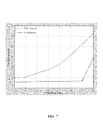
- FIG. 7 is a diagram illustrating the relationship between rank of the matrix comprising the orthogonal polynomial and the orders of the orthogonal polynomial according to an embodiment of the invention.
- the solid line represents the embodiments of the invention, while the dotted line represents the convention method.
- FIG. 7 means that, with the use of orthogonal functions of embodiments of the present invention, a process for solving the predistortion coefficient converges faster, with more stable values.
- the conventional method shown in FIG. 7 with the increase in the order of orthogonal functions, the stability decreased rapidly in solving the comparison predistortion coefficients by using the convention method.
- With an increase in polynomial order it will be harder to maintain orthogonal among the high-order polynomial with the each previous polynomials, thus resulting in higher correlation, and larger condition number.
Landscapes
- Engineering & Computer Science (AREA)
- Physics & Mathematics (AREA)
- Power Engineering (AREA)
- Nonlinear Science (AREA)
- Algebra (AREA)
- General Physics & Mathematics (AREA)
- Mathematical Analysis (AREA)
- Mathematical Optimization (AREA)
- Pure & Applied Mathematics (AREA)
- Amplifiers (AREA)
- Signal Processing (AREA)
- Computer Networks & Wireless Communication (AREA)
Abstract
Description
-
- wherein K represents a non-linear order, Q represents a memory depth, wkq represents the updated predistortion coefficient, ϕk(x) represents a plurality of non-linear transformation of the input baseband signal, wherein any two of different ϕk(x) are orthogonal. X(n) represents the current input sample, x(n−1) presents an input sample of a previous time instance, . . . x(n−q) represents input sample of q previous sampling time instances, and so on. Due to the orthogonal characteristics, self correlation function matrix corresponding to ϕk(x) has good condition numbers, therefore the phenomena of value instability will not occur when solving the coefficient for the orthogonal polynomials. In the field of numerical analysis, the condition number of a function with respect to an argument measures how much the output value of the function can change for a small change in the input argument. This is used to measure how sensitive a function is to changes or errors in the input, and how much error in the output results from an error in the input. Note the self correlation function matrix correspond to ϕk(x). The good condition numbers of self correlation function matrix means that variation ranges of eigenvalues of the matrix are relatively small. In solving matrix problems, good condition numbers means that minor variation in choosing values for the matrix elements will not result in great variation in the values of the coefficient which are solved.
represents me orthogonal polynomial, and k represents the order of the polynomial. For amplitude probability distribution of different power amplifier output signals, orthogonal polynomial basis functions will be different.
ϕ1(z)=z
ϕ2(z)=5.14z 2−3.87z
ϕ3(z)=22.69z 3−30.41z 2+9.17z
ϕ4(z)=95.62z 4−180.16z 3+103.45z 2−17.33z
ϕ5(z)=394.69z 5−951.81z 4+796.98z 3−266.93z 2+28.74z (2)
. . .
ϕ1(z)=z
ϕ2(z)=8.79z 2−2.75z
ϕ3(z)=56.15z 3−37.78z 2+5.6z
ϕ4(z)=299.18z 4−321.85z 3+103.61z 2−9.72z
ϕ5(z)=1404.41z 5−2132.95z 4+1106.14z 3−227.79z 2+15.28z (4)
wherein K represents a non-linear order, Q represents a memory depth, wkq represents the updated predistortion coefficient, ϕk(x) represents a plurality of non-linear transformation of the input baseband signal, wherein any two of different ϕk(x) are orthogonal.
Claims (10)
Applications Claiming Priority (3)
| Application Number | Priority Date | Filing Date | Title |
|---|---|---|---|
| CN201610736548 | 2016-08-26 | ||
| CN201610736548.1 | 2016-08-26 | ||
| CN201610736548.1A CN107786174B (en) | 2016-08-26 | 2016-08-26 | Circuit and method for predistortion |
Publications (2)
| Publication Number | Publication Date |
|---|---|
| US20190097589A1 US20190097589A1 (en) | 2019-03-28 |
| US10298366B2 true US10298366B2 (en) | 2019-05-21 |
Family
ID=61439610
Family Applications (1)
| Application Number | Title | Priority Date | Filing Date |
|---|---|---|---|
| US15/278,047 Active 2036-10-16 US10298366B2 (en) | 2016-08-26 | 2016-09-28 | Circuit and method for predistortion |
Country Status (2)
| Country | Link |
|---|---|
| US (1) | US10298366B2 (en) |
| CN (1) | CN107786174B (en) |
Cited By (1)
| Publication number | Priority date | Publication date | Assignee | Title |
|---|---|---|---|---|
| US10756682B1 (en) * | 2019-02-04 | 2020-08-25 | Mellanox Technologies, Ltd. | Compensating for transmitter nonlinearities |
Families Citing this family (4)
| Publication number | Priority date | Publication date | Assignee | Title |
|---|---|---|---|---|
| CN112838996B (en) * | 2020-12-31 | 2022-03-25 | 京信网络系统股份有限公司 | Digital predistortion coefficient updating method, device, communication equipment and storage medium |
| CN116389203A (en) * | 2021-12-23 | 2023-07-04 | 华为技术有限公司 | A nonlinear correction method, device and system |
| CN117192271B (en) * | 2023-10-08 | 2025-05-13 | 广州羊城电气设备有限公司 | Wire slot cable on-line monitoring system |
| CN119814052B (en) * | 2024-06-25 | 2025-06-10 | 杭州得翼通信技术有限公司 | Communication system |
Citations (3)
| Publication number | Priority date | Publication date | Assignee | Title |
|---|---|---|---|---|
| US20120119831A1 (en) | 2010-11-16 | 2012-05-17 | Chunlong Bai | Orthogonal Basis Function Set for Digital Predistorter |
| CN102522957A (en) | 2011-11-30 | 2012-06-27 | 上海瑞和安琦通信科技有限公司 | Method for improving predistortion performance of radio-frequency power amplifier |
| CN103179074A (en) | 2013-03-20 | 2013-06-26 | 中国科学院上海微系统与信息技术研究所 | Orthogonal polynomial based adaptive predistortion system and method |
Family Cites Families (3)
| Publication number | Priority date | Publication date | Assignee | Title |
|---|---|---|---|---|
| US20080273629A1 (en) * | 2007-05-02 | 2008-11-06 | Beaulieu Norman C | Uwb receiver designs based on a gaussian-laplacian noise-plus-mai model |
| CN101527544B (en) * | 2008-03-05 | 2012-09-12 | 富士通株式会社 | Device and method for identifying inverse characteristic of nonlinear system, power amplifier and predistorter thereof |
| CN102480450B (en) * | 2010-11-30 | 2014-12-10 | 富士通株式会社 | Predistorter control device and method as well as power control state detection method |
-
2016
- 2016-08-26 CN CN201610736548.1A patent/CN107786174B/en active Active
- 2016-09-28 US US15/278,047 patent/US10298366B2/en active Active
Patent Citations (3)
| Publication number | Priority date | Publication date | Assignee | Title |
|---|---|---|---|---|
| US20120119831A1 (en) | 2010-11-16 | 2012-05-17 | Chunlong Bai | Orthogonal Basis Function Set for Digital Predistorter |
| CN102522957A (en) | 2011-11-30 | 2012-06-27 | 上海瑞和安琦通信科技有限公司 | Method for improving predistortion performance of radio-frequency power amplifier |
| CN103179074A (en) | 2013-03-20 | 2013-06-26 | 中国科学院上海微系统与信息技术研究所 | Orthogonal polynomial based adaptive predistortion system and method |
Cited By (1)
| Publication number | Priority date | Publication date | Assignee | Title |
|---|---|---|---|---|
| US10756682B1 (en) * | 2019-02-04 | 2020-08-25 | Mellanox Technologies, Ltd. | Compensating for transmitter nonlinearities |
Also Published As
| Publication number | Publication date |
|---|---|
| US20190097589A1 (en) | 2019-03-28 |
| CN107786174B (en) | 2021-02-05 |
| CN107786174A (en) | 2018-03-09 |
Similar Documents
| Publication | Publication Date | Title |
|---|---|---|
| US20230370937A1 (en) | Method and system for baseband predistortion linearization in multi-channel wideband communication systems | |
| Raich et al. | Orthogonal polynomials for power amplifier modeling and predistorter design | |
| US10298366B2 (en) | Circuit and method for predistortion | |
| US8787494B2 (en) | Modeling digital predistorter | |
| CN101662821B (en) | Signal processing method and communication system | |
| CN111490737A (en) | A kind of nonlinear compensation method and apparatus for power amplifier | |
| US8432220B2 (en) | Linearization device for a power amplifier | |
| TWI536731B (en) | Pre-distortion method, pre-distortion apparatus and machine readable medium | |
| CN102195912A (en) | Digital pre-distortion processing equipment and method | |
| Tahkoubit et al. | Generalized iterative dichotomy PAPR reduction method for multicarrier waveforms | |
| Sezgin | Different Digital Predistortion Techniques for Power Amplifier Linearization | |
| Nair et al. | A comparative study on digital predistortion techniques for Doherty amplifier for LTE applications | |
| Zeng et al. | A crest factor reduction method in digital predistortion for improvement of power efficiency | |
| Zhang et al. | OFDM PAPR reduction with digital amplitude predistortion | |
| Liszewski et al. | Low-complexity FPGA implementation of Volterra predistorters for power amplifiers | |
| KR20140118130A (en) | Apparatus and method of predistortion of multiple nonlinear amplifiers with single feedback loop | |
| Bulusu et al. | Power amplifier effects and peak-to-average power mitigation | |
| Njenga | BANDLIMITED DIGITAL PREDISTORTION OF WIDEBAND RF POWER AMPLIFIERS | |
| HK40047878A (en) | Method and system for baseband predistortion linearization in multi-channel wideband communication systems | |
| Songratthaset et al. | Adaptive polynomials method for FBMC nonlinear power amplifier complex gain | |
| JP4118882B2 (en) | Amplifier predistorter | |
| Yu et al. | Error vector magnitude optimization with cubic metric reduction and out-of-band radiation constraints in OFDM systems | |
| Pasricha et al. | Power amplifier memory-less nonlinear modeling | |
| Berndsen | Signal Optimization for Efficient High-Power Amplifier Operation | |
| Tanovic et al. | Baseband Equivalent Models and Digital Predistortion for Mitigating Dynamic Continuous-Time Perturbations in Phase-Amplitude Modulation-Demodulation Schemes (Expanded version) |
Legal Events
| Date | Code | Title | Description |
|---|---|---|---|
| AS | Assignment |
Owner name: MONTAGE TECHNOLOGY (SHANGHAI) CO., LTD., CHINA Free format text: ASSIGNMENT OF ASSIGNORS INTEREST;ASSIGNORS:HU, GANG;WANG, XUEPENG;NIE, YUANFEI;REEL/FRAME:040166/0481 Effective date: 20160926 |
|
| AS | Assignment |
Owner name: MONTAGE LZ TECHNOLOGIES (CHENGDU) CO., LTD., CHINA Free format text: ASSIGNMENT OF ASSIGNORS INTEREST;ASSIGNOR:MONTAGE TECHNOLOGY (SHANGHAI) CO., LTD.;REEL/FRAME:044033/0131 Effective date: 20171013 Owner name: MONTAGE LZ SEMICONDUCTOR (SHANGHAI) CO., LTD., CHI Free format text: ASSIGNMENT OF ASSIGNORS INTEREST;ASSIGNOR:MONTAGE TECHNOLOGY (SHANGHAI) CO., LTD.;REEL/FRAME:044033/0131 Effective date: 20171013 |
|
| FEPP | Fee payment procedure |
Free format text: PETITION RELATED TO MAINTENANCE FEES GRANTED (ORIGINAL EVENT CODE: PTGR); ENTITY STATUS OF PATENT OWNER: SMALL ENTITY |
|
| STPP | Information on status: patent application and granting procedure in general |
Free format text: NOTICE OF ALLOWANCE MAILED -- APPLICATION RECEIVED IN OFFICE OF PUBLICATIONS |
|
| STPP | Information on status: patent application and granting procedure in general |
Free format text: PUBLICATIONS -- ISSUE FEE PAYMENT VERIFIED |
|
| STCF | Information on status: patent grant |
Free format text: PATENTED CASE |
|
| AS | Assignment |
Owner name: SINO WEALTH ELECTRONIC LTD., CHINA Free format text: ASSIGNMENT OF ASSIGNORS INTEREST;ASSIGNORS:MONTAGE LZ SEMICONDUCTOR (SHANGHAI) CO., LTD.;MONTAGE LZ TECHNOLOGIES (CHENGDU) CO., LTD.;REEL/FRAME:052312/0033 Effective date: 20200401 |
|
| MAFP | Maintenance fee payment |
Free format text: PAYMENT OF MAINTENANCE FEE, 4TH YR, SMALL ENTITY (ORIGINAL EVENT CODE: M2551); ENTITY STATUS OF PATENT OWNER: SMALL ENTITY Year of fee payment: 4 |