US10278322B2 - Hinged folding toolbar for an agricultural implement - Google Patents
Hinged folding toolbar for an agricultural implement Download PDFInfo
- Publication number
- US10278322B2 US10278322B2 US14/977,005 US201514977005A US10278322B2 US 10278322 B2 US10278322 B2 US 10278322B2 US 201514977005 A US201514977005 A US 201514977005A US 10278322 B2 US10278322 B2 US 10278322B2
- Authority
- US
- United States
- Prior art keywords
- toolbar
- articulating
- hinge
- base
- agricultural implement
- Prior art date
- Legal status (The legal status is an assumption and is not a legal conclusion. Google has not performed a legal analysis and makes no representation as to the accuracy of the status listed.)
- Active, expires
Links
Images


Classifications
-
- A—HUMAN NECESSITIES
- A01—AGRICULTURE; FORESTRY; ANIMAL HUSBANDRY; HUNTING; TRAPPING; FISHING
- A01B—SOIL WORKING IN AGRICULTURE OR FORESTRY; PARTS, DETAILS, OR ACCESSORIES OF AGRICULTURAL MACHINES OR IMPLEMENTS, IN GENERAL
- A01B73/00—Means or arrangements to facilitate transportation of agricultural machines or implements, e.g. folding frames to reduce overall width
- A01B73/02—Folding frames
- A01B73/04—Folding frames foldable about a horizontal axis
- A01B73/044—Folding frames foldable about a horizontal axis the axis being oriented in a longitudinal direction
Definitions
- the present disclosure is directed toward a toolbar hinge for an agricultural implement.
- the art continues to be developed with the aim of improving capabilities of the implements while operating in the field optimizing stability of the implements when in a working position and in a transport position.
- agricultural implements are not optimal. Despite the need to occupy minimal space during storage, maneuvering, and transit, agricultural implements have relatively large widths in transport positions as a proportion of their dimensions when in working positions during operation. A smaller implement may be required to meet transport or machine storage limitations than required to match the tractor horsepower for field work. The increase in the number of passes needed to work an area directly results in greater fuel, time, and labor requirements than necessary.
- FIG. 1A is a perspective view of a conventional embodiment of an agricultural implement 1 including a base toolbar 2 , a first articulating toolbar 4 a , a second articulating toolbar 4 b , a first hinge 6 a , a second hinge 6 b , lockdown pins 8 a and 8 b , and three sets of row units 10 a , 10 b , and 10 c , each including a plurality of row units 20 for strip tilling a ground surface.
- This embodiment illustrates strip till row units mounted to the toolbars. Other attachments may be used.
- the agricultural implement 1 is shown in a first position with the first articulating toolbar 4 a and the second articulating toolbar 4 b extended outwardly, substantially parallel to the ground (x-z) plane with the base toolbar 2 having a first end connected to the first hinge 6 a and having a second end connected to the second hinge 6 b .
- the base toolbar 2 , the first articulating toolbar 4 a , and the second articulating toolbar 4 b are each connected to a set of row units 10 a , 10 b , and 10 c , respectively.
- the first articulating toolbar 4 a and the second articulating toolbar 4 b are connected to the first hinge 6 a and the second hinge 6 b , respectively.
- FIG. 1B and FIG. 1C are close-up perspective views of the connection between the base toolbar 2 and the first articulating toolbar 4 a by the first hinge 6 a , the first hinge 6 a including a lockdown pin 8 a .
- FIG. 1B illustrates the direction of insertion of the lockdown pin 8 a into the first hinge 6 a .
- FIG. 1C shows the lockdown pin 8 a inserted into the first hinge 6 a , preventing rotation of the hinge 6 a and preventing the position of the first articulating toolbar 4 a from changing relative to that of the base toolbar 2 .
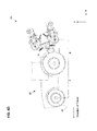
- FIG. 2A is a perspective view of the conventional embodiment of the agricultural implement 1 including the base toolbar 2 , the first articulating toolbar 4 a , the second articulating toolbar 4 b , the first hinge 6 a , the second hinge 6 b , and the three sets of row units 10 a , 10 b , and 10 c .
- the agricultural implement 1 is shown in a second position with the first articulating toolbar 4 a and the second articulating toolbar 4 b folded, the base toolbar 2 having a first end connected to the first hinge 6 a and having a second end connected to the second hinge 6 b .
- the first articulating toolbar 4 a articulates about the first end of the base toolbar 2 as both the first articulating toolbar 4 a and the base toolbar 2 are connected by the first hinge 6 a
- the second articulating toolbar 4 b articulates about the second end of the base toolbar 2 as both the second articulating toolbar 4 b and the base toolbar 2 are connected by the second hinge 6 b
- the rotation of the first hinge 6 a and the second hinge 6 b occur substantially about the x-axis.
- the ranges of motion of the first articulating toolbar 4 a and the second articulating toolbar 4 b about the first hinge 6 a and the second hinge 6 b , respectively, are limited due to the placement of the sets of the row units 10 a , 10 b , and 10 c on the base toolbar 2 , the first articulating toolbar 4 a , and the second articulating toolbar 4 b , respectively.
- the set of row units 10 a specifically a row unit 20 a , connected to the base toolbar 2 and the set of row units 10 b , specifically a row unit 20 b , connected to the first articulating toolbar 4 a come into contact, limiting articulation of the first articulating toolbar 4 a about the base toolbar 2 .
- the set of the row units 10 a connected to the base toolbar 2 and the set of the row units 10 c connected to the second articulating toolbar 4 b come into contact, limiting articulation of the second articulating toolbar 4 b about the base toolbar 2 .
- FIG. 2B is a front view of the conventional embodiment of the agricultural implement 1 including the base toolbar 2 , the first articulating toolbar 4 a , the second articulating toolbar 4 b , the first hinge 6 a , the second hinge 6 b , and the three sets of row units 10 a , 10 b , and 10 c , each having a plurality of the row units 20 .
- the agricultural implement 1 is shown in the y-z plane in a second position with the first articulating toolbar 4 a and the second articulating toolbar 4 b folded, the base toolbar 2 having a first end connected to the first hinge 6 a and a second end connected to the second hinge 6 b .
- the base toolbar 2 , the first articulating toolbar 4 a , and the second articulating toolbar 4 b are connected to the sets of row units 10 a , 10 b , and 10 c , respectively.
- the first articulating toolbar 4 a articulates substantially in the y-z plane about the base toolbar 2 as both the first articulating toolbar 4 a and the base toolbar 2 are connected by the first hinge 6 a .
- the second articulating toolbar 4 b articulates substantially in the y-z plane about the second end of the base toolbar 2 as both the second articulating toolbar 4 b and the base toolbar 2 are connected by the second hinge 6 b.
- FIG. 2C is a side view of the conventional embodiment of the agricultural implement 1 including the base toolbar 2 , the first articulating toolbar 4 a , the first hinge 6 a , and the sets of the row units 10 a and 10 b .
- the agricultural implement 1 is shown in the x-y plane in a second position with the first articulating toolbar 4 a folded and connected to the first hinge 6 a , the base toolbar 2 having a first end connected to the first hinge 6 a .
- the base toolbar 2 and the first articulating toolbar 4 a are connected to the sets of row units 10 a and 10 b , respectively.
- the first articulating toolbar 4 a articulates about the first end of the base toolbar 2 as both the first articulating toolbar 4 a and the base toolbar 2 are connected by the first hinge 6 a , with the first hinge 6 a rotating substantially about the x-axis, in this embodiment forming a tilt angle ⁇ with the horizontal of approximately zero degrees.
- first articulating toolbar 4 a As the first articulating toolbar 4 a articulates about the first hinge 6 a , contact between the set of row units 10 b of the first articulating toolbar 4 a and the set of the row units 10 a of the base toolbar 2 , as provided in the description of FIG. 2A , prevents further articulation and limits the range of rotation of the first hinge 6 a . Because tilt angle ⁇ is zero in this embodiment, the first articulating toolbar 4 a moves substantially in the y-z plane as it articulates, the position of the center of gravity (CG) of the agricultural implement 1 along the x-axis remains stationary and does not vary with articulation of the first articulating toolbar 4 a.
- CG center of gravity
- FIG. 2D is a side view of the conventional embodiment of the agricultural implement 1 , shown in the x-y plane in the second (transport) position described by FIG. 2C , and connected to the rear of a tractor 26 .
- the tractor 26 has a wheelbase A spanning the distance between the centers of a front wheel 22 and a rear wheel 24 , while the distance B represents the distance from the center of the rear wheel 24 to the CG of the agricultural implement 1 in the transport position.
- the combined mass of the tractor 26 and the mass of the agricultural implement 1 are supported by the front wheels 22 and the rear wheels 24 .
- the location of the CG of the tractor 26 is generally within the wheelbase A while the CG of the agricultural implement 1 is behind the centerline of the rear wheel since all of the agricultural implement 1 is connected to and supported at the back of the tractor 26 , behind the center of the rear wheel 24 .
- the combined CG of the tractor 26 and the agricultural implement 1 is generally still located within the wheelbase A of the tractor 26 , but closer to the rear of the tractor 26 than the CG of just the tractor 26 itself.
- FIG. 2E is a front view of the conventional embodiment of the agricultural implement 1 connected to the tractor 26 .
- the agricultural implement 1 is shown in an extended (working) position, with similar components to that described by FIG. 2B , including the base toolbar 2 , the first articulating toolbar 4 a , the second articulating toolbar 4 b , the first hinge 6 a , the second hinge 6 b , and the three sets of row units 10 a , 10 b , and 10 c , each having a plurality of the row units 20 that contact the ground surface.
- the agricultural implement 1 exerts a draft load on the tractor 26 , draft load defined as the force needed to pull the implement parallel to the direction of travel.
- first articulating toolbar 4 a and the second articulating toolbar 4 b , and the set of row units 10 b and 10 c of the agricultural implement 1 have an undesirable tendency to rise up particularly as the row unit 20 furthest from the first and second hinges 6 a and 6 b , respectively, encounter hard or slightly uneven ground surfaces during operation behind the tractor 26 due to insufficient downward force acting upon them (e.g.
- the row unit 20 n is not even with the row unit 20 p ), requiring the use of a lockdown pin 8 a and lockdown pin 8 b to ensure the toolbars 4 a and 4 b remain in the necessary extended position, and the sets of row units 10 b and 10 c connected to the toolbars 4 a and 4 b remain in contact with a ground surface.
- the present disclosure is directed to an agricultural implement equipped with one or more articulating toolbars designed such that as they each rotate about the pivot axes of hinges the toolbars and their attachments do not make contact with one another.
- the disclosure pertains to a system and method for allowing folding toolbars to articulate in such a way to reduce the need for lockdown pins since the tilted hinges provide an additional downward force component due to the draft load acting upon the toolbars, to resist vertical movement of the toolbars as the agricultural implement moves forward. This reduces the tendency for inadvertent movement of the toolbars as the agricultural implement encounters uneven ground surfaces.
- the toolbar hinges described below allow a tractor of a given size the capability to pull a larger toolbar span and to work more acres when extended in the working condition. Consequently, the agricultural implement can cover more acres for a given time period and number of passes, reducing fuel and labor costs and increasing efficiency.
- FIG. 1A is a perspective view of an embodiment of a toolbar assembly, according to the conventional art
- FIG. 1B is a close-up perspective view of an embodiment of a hinge and a lockdown pin, according to the conventional art
- FIG. 1C is a close-up perspective view of a hinge with a lockdown pin inserted, according to the conventional art
- FIG. 2A is a perspective view of an embodiment of a toolbar assembly, according to the conventional art
- FIG. 2B is a front view of an embodiment of a toolbar assembly, according to the conventional art
- FIG. 2C is a side view of an embodiment of a toolbar assembly, according to the conventional art.
- FIG. 2D is a side view of an embodiment of an agricultural implement in the transport position, and connected to the rear of a tractor, according to the conventional art;
- FIG. 2E is a front view of an embodiment of an agricultural implement connected to a tractor, according to the conventional art
- FIG. 3A is a perspective view of an embodiment of a toolbar assembly
- FIG. 3B is a close-up perspective view of an embodiment of a tilted hinge
- FIG. 3C is a close-up perspective view of an embodiment of a tilted hinge
- FIG. 4A is a perspective view of an embodiment of a toolbar assembly
- FIG. 4B is a front view of an embodiment of a toolbar assembly
- FIG. 4C is a side view of an embodiment of a toolbar assembly
- FIG. 4D is a side view of an embodiment of an agricultural implement in a transport position, connected to the rear of a tractor;
- FIG. 4E is a front view of an embodiment of an agricultural implement connected to a tractor
- FIG. 4F is a force diagram representing a hinge mounted at a tilt angle with a horizontal surface of an agricultural implement.
- FIG. 4G is an exploded perspective view of an embodiment of the toolbar hinge, connecting the second articulating toolbar and the base toolbar.
- FIG. 3A is a perspective view of an embodiment of an agricultural implement 101 including a base toolbar 102 , a first articulating toolbar 104 a , a second articulating toolbar 104 b , a first hinge 106 a , a second hinge 106 b , and three sets of row units 110 a , 110 b , and 110 c , each including a plurality of row units 20 .
- This embodiment illustrates strip till row units 110 mounted to the base toolbar 102 , the first articulating toolbar 104 a , and the second articulating toolbar 104 b .
- Other attachments may be used.
- the agricultural implement 101 is shown in a first position with the first articulating toolbar 104 a and the second articulating toolbar 104 b extended outwardly, substantially parallel to the ground (x-z) plane with the base toolbar 102 having a first end connected to the first hinge 106 a and a second end connected to the second hinge 106 b .
- the base toolbar 102 , the first articulating toolbar 104 a , and the second articulating toolbar 104 b are connected to the sets of row units 110 a , 110 b , and 110 c , respectively.
- the first articulating toolbar 104 a and the second articulating toolbar 104 b are connected to the first hinge 106 a and the second hinge 106 b , respectively.
- FIG. 3B and FIG. 3C are close-up perspective views of the connection between the base toolbar 102 and the first articulating toolbar 104 a by the first hinge 106 a .
- FIG. 3B shows the first hinge 106 a may not have the lockdown pin 8 a of the conventional art, as shown in FIG. 1B and FIG. 1C .
- FIG. 3C shows the tilt angle ⁇ formed by the pivot axis of the first hinge 106 a and the ground plane is greater than zero degrees, the pivot axis presenting a tilt angle with the horizontal plane such that the rearward end of the pivot axis is located at a greater distance above a ground plane than a forward end of the pivot axis.
- FIG. 4A is a perspective view of an embodiment of the agricultural implement 101 including the base toolbar 102 , the first articulating toolbar 104 a , the second articulating toolbar 104 b , the first hinge 106 a , the second hinge 106 b , and three sets of row units 110 a , 110 b , and 110 c , as described by FIG. 3A .
- the agricultural implement 101 is shown in a second (transport) position with the first articulating toolbar 104 a and the second articulating toolbar 104 b folded, the base toolbar 102 having a first end connected to the first hinge 106 a and having a second end connected to the second hinge 106 b .
- the base toolbar 102 , the first articulating toolbar 104 a , and the second articulating toolbar 104 b are each connected to one set of row units 110 a , 110 b , and 110 c , respectively, each having a plurality of row units 20 .
- the first articulating toolbar 104 a articulates about the first end of the base toolbar 102 as both the first articulating toolbar 104 a and the base toolbar 102 are connected by the first hinge 106 a
- the second articulating toolbar 104 b articulates about the second end of the base toolbar 102 as both the second articulating toolbar 104 b and the base toolbar 102 are connected by the second hinge 106 b .
- the rotation of the first hinge 106 a and the second hinge 106 b occur about a pivot axis located substantially in the x-y plane.
- the range of rotation of the first articulating toolbar 104 a and the second articulating toolbar 104 b about the first hinge 106 a and about the second hinge 106 b , respectively, as they transition from the first (extended, working) position and approach the second (folded, transport) position is limited by the independent kinematic relationships between the first articulating toolbar 104 a and the base toolbar 102 , and the second articulating toolbar 104 b and the base toolbar 102 , instead of interference between the sets of row units 110 c and 110 a each is connected to.
- Tilt angle ⁇ ( FIG. 3C ) that exists between each of the pivot axes of the first hinge 106 a and the second hinge 106 b and the ground plane (x-z plane).
- Tilt angle ⁇ may be approximately in the range of 5 to 15 degrees from the horizontal (x-axis). In one embodiment the tilt angle ⁇ may be approximately 8 degrees. In another embodiment the tilt angle ⁇ may be approximately 12 degrees.
- the second hinge 106 b is further described by FIG. 4G .
- the combined length of the first articulating toolbar 104 a and the second articulating toolbar 104 b is not more than the length of the base toolbar 102 .
- the set of row units 110 a connected to the base toolbar 102 and the set of row units 110 b connected to the first articulating toolbar 104 a do not come into contact.
- the relationship between the base toolbar 102 and the second articulating toolbar 104 b is similar.
- the eventual contact between the base toolbar 102 and the second articulating toolbar 104 b or contact between the second articulating toolbar 104 b and the second hinge 106 b limits further articulation of the second articulating toolbar 104 b about the base toolbar 102 , rather than any interference involving the sets of row units 110 a and 110 c . Because of this, the range of rotation of the second articulating toolbar 104 b is greater in this embodiment than in the conventional embodiment described by FIG. 2A .
- FIG. 4B is a front view of an embodiment of the agricultural implement 101 similar to that shown by FIG. 4A including the base toolbar 102 , the first articulating toolbar 104 a , the second articulating toolbar 104 b , the first hinge 106 a , the second hinge 106 b , and the three sets of row units 110 a , 110 b , and 110 c .
- the agricultural implement 101 is shown in the y-z plane in a second position with the first articulating toolbar 104 a and the second articulating toolbar 104 b folded, the base toolbar 102 having the first end connected to the first hinge 106 a and the second end connected to the second hinge 106 b .
- the base toolbar 102 , the first articulating toolbar 104 a , and the second articulating toolbar 104 b are connected to the sets of row units 110 a , 110 b , and 110 c , respectively, each having a plurality of row units 20 .
- the first articulating toolbar 104 a articulates primarily in the y-z plane about the first end of the base toolbar 102 as both the first articulating toolbar 104 a and the base toolbar 102 are connected by the first hinge 106 a
- the second articulating toolbar 104 b articulates primarily in the y-z plane about the second end of the base toolbar 102 as both the second articulating toolbar 104 b and the base toolbar 102 are connected by the second hinge 106 b.
- the first articulating toolbar 104 a and the second articulating toolbar 104 b form angles ⁇ 1 and ⁇ 2 , respectively, with the ground plane (x-z plane) which are smaller than those of the embodiment of FIG. 2B .
- ⁇ 1 and ⁇ 2 are zero degrees when the first articulating toolbar 104 a and the second articulating toolbar 104 b are each in the second position.
- tilt angle ⁇ is greater than zero degrees ( FIG. 3C ) the first articulating toolbar 104 a and second articulating toolbar 104 b , and the sets of row units 110 b , 110 c connected to their respective toolbars, move away from the set of row units 110 a connected to the base toolbar 102 as the first articulating toolbar 104 a and the second articulating toolbar 104 b articulate into the second position, which avoids interference between the three sets of row units 110 a , 110 b , 110 c (see FIG. 4C ). The same is true of the relationship between the second articulating toolbar 104 b and the base toolbar 102 .
- FIG. 4C is a side view of an embodiment of the agricultural implement 101 including the base toolbar 102 , the first articulating toolbar 104 a , and the first hinge 106 a .
- the agricultural implement 101 is shown in the x-y plane in the second (folded, transport) position with the first articulating toolbar 104 a folded and connected to the first hinge 106 a beneath, the base toolbar 102 having the first end connected to the first hinge 106 a .
- the base toolbar 102 and the first articulating toolbar 104 a are connected to the sets of row units 110 a , 110 b , respectively, each having a plurality of row units 20 .
- the first articulating toolbar 104 a articulates about the first end of the base toolbar 102 as both are connected by the first hinge 106 a , with the first hinge 106 a oriented substantially in the y-z plane and forming the tilt angle ⁇ that exists between each of the pivot axes of the first hinge 106 a and the second hinge 106 b and the ground plane (x-z plane).
- the tilt angle ⁇ may be approximately in the range of 5 to 15 degrees from the horizontal (x-axis).
- the set of row units 110 a connected to the base toolbar 102 and the set of row units 110 b connected to the first articulating toolbar 104 a do not come into contact.
- the sets of row units 110 a and 110 b to which the base toolbar 102 and the first articulating toolbar 104 a , respectively, are connected move apart enough such that there is no contact between the sets of row units 110 a and 110 b , unlike that described by FIG. 2C .
- the set of row units 110 b connected to the first articulating toolbar 104 a has sufficient clearance in its range of motion so as not to make contact with the set of row units 110 a connected to the base toolbar 102 .
- the pivot axes of the first hinge 106 a and the second hinge 106 b about which the first articulating toolbar 104 a and the second articulating toolbar 104 b , respectively, articulate are substantially parallel with the direction of travel and form an tilt angle ⁇ with the ground (x-z) plane.
- the smaller cross section of the second position of the agricultural implement 101 in this embodiment in both width (z-axis) and height (y-axis), compared with the cross section of the second position of the embodiment described in FIG. 2A through FIG. 2C allows the agricultural implement 101 to maneuver in smaller areas, whether in open space, inside a building or structure, as well as more easily transported on highways.
- FIG. 4D is a side view of an agricultural implement 101 , shown in the x-y plane in the second (transport) position described by FIG. 4C , and connected to the rear of a tractor 26 .
- the tractor 26 has a wheelbase A spanning the distance between the centers of a front wheel 22 and a rear wheel 24 , while the distance B′ represents the distance from the center of the rear wheel 24 to the CG of the agricultural implement 101 in the transport position.
- the combined mass of the tractor 26 and the mass of the agricultural implement 101 are supported by the front wheels 22 and the rear wheels 24 .
- the location of the CG of the tractor 26 is generally within the wheelbase A while the CG of the agricultural implement 101 is behind the centerline of the rear wheel since the whole of the agricultural implement 101 is connected to and supported at the back of the tractor 26 , behind the center of the rear wheel 24 .
- the combined CG of the tractor 26 and the agricultural implement 101 is generally still located within the wheelbase A of the tractor 26 , but closer to the rear of the tractor 26 than the CG of just the tractor 26 itself.
- the payload capability of the tractor 26 in this example is greater than that of the tractor 26 described by the background art of FIG. 2D because B′ is shorter in this example than B is in that described by FIG. 2D .
- the CG of the agricultural implement 101 in this example is closer to that of the tractor 26 , reducing the moment the CG of the agricultural implement 101 exerts about the center of the rear wheel 24 , reducing the effect that must be counterbalanced by the moment the tractor's 26 CG creates about the center of the rear wheel 24 .
- the tractor 26 With the tractor's 26 mass more evenly distributed over the front wheels 22 and the rear wheels 24 , in this example the tractor 26 is more stable, consequently allowing the tractor 26 to carry more payload before exceeding the weight limit of the front wheels 22 or the rear wheels 24 than the example described by FIG. 2D .
- FIG. 4E is a front view of an embodiment of the agricultural implement 101 connected to the tractor 26 .
- the agricultural implement 101 is shown in an extended (working) position, with similar components to that described by FIG. 4A , including the base toolbar 102 , the first articulating toolbar 104 a , the second articulating toolbar 104 b , the first hinge 106 a , the second hinge 106 b , and the three sets of row units 110 a , 110 b , and 110 c , each having a plurality of the row units 20 that contact the ground surface.
- the agricultural implement 101 exerts a draft load on the tractor 26 , draft load defined as the force needed to pull the implement parallel to the direction of travel.
- first articulating toolbar 104 a and the second articulating toolbar 104 b , and the respective sets of row units 110 b and 110 c connected to them are tilted forward, the first articulating toolbar 104 a and the second articulating toolbar 104 b each have an additional normal force component acting downward due to the draft load which is parallel to the forward direction of travel of the agricultural implement 101 . Because the pivot axes of the hinges 106 a and 106 b are angled tilted forward relative to the ground (x-z) plane at an angle ⁇ ( FIG. 4C ), there exists a normal component of the draft load which restricts vertical movement.
- This restriction stabilizes the first articulating toolbar 104 a and the second articulating toolbar 104 b , and reduces the tendency for inadvertent movement of said members relative to the base toolbar 102 when the plurality of the row units 20 of the agricultural implement 101 encounters uneven ground surfaces. Since the first articulating toolbar 104 a and the second articulating toolbar 104 b are tilted forward in this manner, the need for the agricultural implement 101 to be equipped with lockdown pins 8 a and 8 b (i.e. the conventional implement shown in FIG. 1A - FIG. 1C ) is eliminated.
- the set of row units 110 c connected to the first articulating toolbar 104 a and the set of row units 110 b connected to the second articulating toolbar 104 b of the agricultural implement 1 tend to remain in place when encountering hard or uneven ground surfaces more than the example of the conventional art described by FIG. 2E .
- FIG. 4F is a force diagram representing a hinge 106 mounted at a tilt angle ⁇ with a horizontal surface of an agricultural implement 101 , similar to that described in FIG. 4C . If the tilt angle ⁇ is zero, as in the background art, the draft force Fd is equal to the horizontal force Fh, and there is no additional normal force Fn applied to the hinge 106 . If the tilt angle ⁇ is greater than zero, an additional normal force Fn is applied to the hinge 106 .
- the tilt angle ⁇ is equal to 12 degrees and the draft force Fd is 3,000 lbs.
- the tilt angle ⁇ is equal to 8 degrees and the draft force Fd is 3,000 lbs.
- the additional normal force Fn is applied to both articulating toolbars 104 a and 104 b , and reduces the need for lockdown pins 8 a and 8 b , as described by FIG. 1B and FIG. 1C of the background art.
- FIG. 4G is an exploded perspective view of an embodiment of the toolbar hinge 106 b , connecting the second articulating toolbar 104 b and the base toolbar 102 .
- a hinge pin 108 b disposed inside the second hinge 106 b connects the base toolbar 102 to the second articulating toolbar 104 b .
- a lockdown pin 8 b may optionally connect bracket holes 107 c and 107 d , with toolbar holes 109 c and 109 d , respectively, (the toolbar hole 109 d is not visible in this view).
- the lockdown pin 8 b connects the second articulating toolbar 104 b to the base toolbar 102 , and prevents the second articulating toolbar 104 b from articulating about the base toolbar 102 .
- the axis of the 106 b forms an angle ⁇ with a horizontal plane.
- the first hinge 106 a connects the first articulating toolbar 104 a to the base toolbar 102 in the identical manner.
Abstract
A system of folding toolbars on an agricultural implement having a base toolbar, two articulating toolbars, multiple attachments to the toolbar, and a pair of hinges, with each toolbar connected to attachments. The base toolbar is located orthogonally to the direction of travel of the agricultural implement and connected to a hinge at each end, the hinges are each further connected to an articulating toolbar. Each of the toolbars is connected to a set of attachments. Each articulating toolbar rotates about the base on a pivot axis along the direction of travel of the agricultural implement and tilted relative to the ground plane, such that the center of gravity (CG) moves forward in the transport position and a normal force is applied to the articulating toolbars to resist vertical movement when in field position.
Description
Field of the Disclosure
The present disclosure is directed toward a toolbar hinge for an agricultural implement.
Description of the Related Art
The continued need to improve upon the prior art in the field of agricultural implements has resulted in the introduction of a number of folding toolbars, able to be placed in multiple positions to accommodate both operational and transportation requirements.
The art continues to be developed with the aim of improving capabilities of the implements while operating in the field optimizing stability of the implements when in a working position and in a transport position.
Many agricultural implements require lockdown pins to prevent or reduce unintended motion of articulating toolbars as the agricultural implements traverse uneven surfaces or hard to penetrate soils. The positioning of the toolbar on the back of the tractor places a heavy load on the tractor, leading to non-ideal circumstances such as instability, too much rear weight bias, and ultimately reducing the maximum payload the tractor can handle.
Further, conventional embodiments of agricultural implements are not optimal. Despite the need to occupy minimal space during storage, maneuvering, and transit, agricultural implements have relatively large widths in transport positions as a proportion of their dimensions when in working positions during operation. A smaller implement may be required to meet transport or machine storage limitations than required to match the tractor horsepower for field work. The increase in the number of passes needed to work an area directly results in greater fuel, time, and labor requirements than necessary.
As the first articulating toolbar 4 a articulates about the first hinge 6 a from the first (extended, working) position of the agricultural implement 1 to the second (folded, transport) position of the agricultural implement 1 (folded), the set of row units 10 a, specifically a row unit 20 a, connected to the base toolbar 2 and the set of row units 10 b, specifically a row unit 20 b, connected to the first articulating toolbar 4 a come into contact, limiting articulation of the first articulating toolbar 4 a about the base toolbar 2.
As the second articulating toolbar 4 b articulates about the second hinge 6 b from the first position of the agricultural implement 1 (extended) to the second position of the agricultural implement 1 (folded), the set of the row units 10 a connected to the base toolbar 2 and the set of the row units 10 c connected to the second articulating toolbar 4 b come into contact, limiting articulation of the second articulating toolbar 4 b about the base toolbar 2.
As the first articulating toolbar 4 a articulates about the first hinge 6 a, contact between the set of the row units 10 b of the first articulating toolbar 4 a and the set of the row units 10 a of the base toolbar 2, as provided in the description of FIG. 2A , prevents further articulation and limits the range of rotation of the first hinge 6 a, forming angle α1 of about 55 degrees with the horizontal.
As the second articulating toolbar 4 b articulates about the second hinge 6 b, contact between the set of the row units 10 c of the second articulating toolbar 4 b and the set of the row units 10 a of the base toolbar 2, as provided in the description of FIG. 2A , prevents further articulation and limits the range of rotation of the second hinge 6 b, forming angle α2 of about 55 degrees with the horizontal.
As the first articulating toolbar 4 a articulates about the first hinge 6 a, contact between the set of row units 10 b of the first articulating toolbar 4 a and the set of the row units 10 a of the base toolbar 2, as provided in the description of FIG. 2A , prevents further articulation and limits the range of rotation of the first hinge 6 a. Because tilt angle β is zero in this embodiment, the first articulating toolbar 4 a moves substantially in the y-z plane as it articulates, the position of the center of gravity (CG) of the agricultural implement 1 along the x-axis remains stationary and does not vary with articulation of the first articulating toolbar 4 a.
The combined mass of the tractor 26 and the mass of the agricultural implement 1 are supported by the front wheels 22 and the rear wheels 24. The location of the CG of the tractor 26 is generally within the wheelbase A while the CG of the agricultural implement 1 is behind the centerline of the rear wheel since all of the agricultural implement 1 is connected to and supported at the back of the tractor 26, behind the center of the rear wheel 24. The combined CG of the tractor 26 and the agricultural implement 1 is generally still located within the wheelbase A of the tractor 26, but closer to the rear of the tractor 26 than the CG of just the tractor 26 itself.
By themselves the first articulating toolbar 4 a and the second articulating toolbar 4 b, and the set of row units 10 b and 10 c of the agricultural implement 1 have an undesirable tendency to rise up particularly as the row unit 20 furthest from the first and second hinges 6 a and 6 b, respectively, encounter hard or slightly uneven ground surfaces during operation behind the tractor 26 due to insufficient downward force acting upon them (e.g. the row unit 20 n is not even with the row unit 20 p), requiring the use of a lockdown pin 8 a and lockdown pin 8 b to ensure the toolbars 4 a and 4 b remain in the necessary extended position, and the sets of row units 10 b and 10 c connected to the toolbars 4 a and 4 b remain in contact with a ground surface.
The present disclosure is directed to an agricultural implement equipped with one or more articulating toolbars designed such that as they each rotate about the pivot axes of hinges the toolbars and their attachments do not make contact with one another.
The disclosure pertains to a system and method for allowing folding toolbars to articulate in such a way to reduce the need for lockdown pins since the tilted hinges provide an additional downward force component due to the draft load acting upon the toolbars, to resist vertical movement of the toolbars as the agricultural implement moves forward. This reduces the tendency for inadvertent movement of the toolbars as the agricultural implement encounters uneven ground surfaces.
Further, this minimizes the cross-sectional area of the agricultural implement, reducing both overall height and overall width, due to their kinematic layout compared with other agricultural implements equipped with folding toolbars. When in a folded transport position the width and height required to transport and store the agricultural implement is less than that which would be required were it not for the novel aspects of this disclosure.
The toolbar hinges described below allow a tractor of a given size the capability to pull a larger toolbar span and to work more acres when extended in the working condition. Consequently, the agricultural implement can cover more acres for a given time period and number of passes, reducing fuel and labor costs and increasing efficiency.
The foregoing general description of the illustrative implementations and the following detailed description thereof are merely exemplary aspects of the teachings of this disclosure, and are not restrictive.
A more complete appreciation of the disclosure and many of the attendant advantages thereof will be readily obtained as the same becomes better understood by reference to the following detailed description when considered in connection with the accompanying drawings wherein:
In the drawings, like reference numerals designate identical or corresponding parts throughout the several views. Further, as used herein, the words “a”, “an” and the like generally carry a meaning of “one or more”, unless stated otherwise.
Referring now to the drawings, wherein like reference numerals designate identical or corresponding parts throughout the several views.
In contrast to the conventional embodiment of FIG. 2A , the range of rotation of the first articulating toolbar 104 a and the second articulating toolbar 104 b about the first hinge 106 a and about the second hinge 106 b, respectively, as they transition from the first (extended, working) position and approach the second (folded, transport) position, is limited by the independent kinematic relationships between the first articulating toolbar 104 a and the base toolbar 102, and the second articulating toolbar 104 b and the base toolbar 102, instead of interference between the sets of row units 110 c and 110 a each is connected to.
This is due to the tilt angle β (FIG. 3C ) that exists between each of the pivot axes of the first hinge 106 a and the second hinge 106 b and the ground plane (x-z plane). Tilt angle β may be approximately in the range of 5 to 15 degrees from the horizontal (x-axis). In one embodiment the tilt angle β may be approximately 8 degrees. In another embodiment the tilt angle β may be approximately 12 degrees. The second hinge 106 b is further described by FIG. 4G .
The sets of row units 110 b and 110 c connected to the first articulating toolbar 104 a and the second articulating toolbar 104 b, respectively, each travel on different paths than that shown in the conventional embodiment of FIG. 2A , the path of each passing through both the y-z plane and the x-z plane, rather than only in the y-z plane.
To maintain the kinematic relationship described by FIG. 4A through FIG. 4C , the combined length of the first articulating toolbar 104 a and the second articulating toolbar 104 b is not more than the length of the base toolbar 102.
As the first articulating toolbar 104 a articulates about the first hinge 106 a from the first (extended, working) position of the agricultural implement 101 to the second (folded, transport) position of the agricultural implement 101, the set of row units 110 a connected to the base toolbar 102 and the set of row units 110 b connected to the first articulating toolbar 104 a do not come into contact.
Instead, it is the eventual contact between the base toolbar 102 and the first articulating toolbar 104 a or contact between the first articulating toolbar 104 a and the first hinge 106 a that limits further articulation of the first articulating toolbar 104 a about the base toolbar 102, rather than any interference involving the sets of row units 110 a and 110 b. Because of this the range of rotation of the first hinge 106 a is greater in this embodiment than in the conventional embodiment described by FIG. 2A .
The relationship between the base toolbar 102 and the second articulating toolbar 104 b is similar. The eventual contact between the base toolbar 102 and the second articulating toolbar 104 b or contact between the second articulating toolbar 104 b and the second hinge 106 b limits further articulation of the second articulating toolbar 104 b about the base toolbar 102, rather than any interference involving the sets of row units 110 a and 110 c. Because of this, the range of rotation of the second articulating toolbar 104 b is greater in this embodiment than in the conventional embodiment described by FIG. 2A .
Consequently, in the second (folded, transport) position of the agricultural implement 101 the first articulating toolbar 104 a and the second articulating toolbar 104 b form angles α1 and α2, respectively, with the ground plane (x-z plane) which are smaller than those of the embodiment of FIG. 2B . For example α1 and α2 are zero degrees when the first articulating toolbar 104 a and the second articulating toolbar 104 b are each in the second position.
Since tilt angle β is greater than zero degrees (FIG. 3C ) the first articulating toolbar 104 a and second articulating toolbar 104 b, and the sets of row units 110 b, 110 c connected to their respective toolbars, move away from the set of row units 110 a connected to the base toolbar 102 as the first articulating toolbar 104 a and the second articulating toolbar 104 b articulate into the second position, which avoids interference between the three sets of row units 110 a, 110 b, 110 c (see FIG. 4C ). The same is true of the relationship between the second articulating toolbar 104 b and the base toolbar 102.
As the first articulating toolbar 104 a articulates about the first hinge 106 a from the first (extended, working) position of the agricultural implement 101 to the second (folded, transport) position of the agricultural implement 101, the set of row units 110 a connected to the base toolbar 102 and the set of row units 110 b connected to the first articulating toolbar 104 a do not come into contact.
As the first articulating toolbar 104 a articulates from the first position, in which it is located with the same planar orientation as the base toolbar 102, to the second position in which the first articulating toolbar 104 a moves forward of the plane of the base toolbar 102, the sets of row units 110 a and 110 b to which the base toolbar 102 and the first articulating toolbar 104 a, respectively, are connected move apart enough such that there is no contact between the sets of row units 110 a and 110 b, unlike that described by FIG. 2C . This is due to the forward movement of the first articulating toolbar 104 a along the x-axis relative to the base toolbar 102. Thus, the set of row units 110 b connected to the first articulating toolbar 104 a has sufficient clearance in its range of motion so as not to make contact with the set of row units 110 a connected to the base toolbar 102.
Consequently, the CG of the entire agricultural implement 101 moves forward on the x-axis as it transitions from the first, working position to the second, transport position. The pivot axes of the first hinge 106 a and the second hinge 106 b about which the first articulating toolbar 104 a and the second articulating toolbar 104 b, respectively, articulate are substantially parallel with the direction of travel and form an tilt angle β with the ground (x-z) plane.
Further, the smaller cross section of the second position of the agricultural implement 101 in this embodiment, in both width (z-axis) and height (y-axis), compared with the cross section of the second position of the embodiment described in FIG. 2A through FIG. 2C allows the agricultural implement 101 to maneuver in smaller areas, whether in open space, inside a building or structure, as well as more easily transported on highways.
The combined mass of the tractor 26 and the mass of the agricultural implement 101 are supported by the front wheels 22 and the rear wheels 24. The location of the CG of the tractor 26 is generally within the wheelbase A while the CG of the agricultural implement 101 is behind the centerline of the rear wheel since the whole of the agricultural implement 101 is connected to and supported at the back of the tractor 26, behind the center of the rear wheel 24. The combined CG of the tractor 26 and the agricultural implement 101 is generally still located within the wheelbase A of the tractor 26, but closer to the rear of the tractor 26 than the CG of just the tractor 26 itself.
However, the payload capability of the tractor 26 in this example is greater than that of the tractor 26 described by the background art of FIG. 2D because B′ is shorter in this example than B is in that described by FIG. 2D . The CG of the agricultural implement 101 in this example is closer to that of the tractor 26, reducing the moment the CG of the agricultural implement 101 exerts about the center of the rear wheel 24, reducing the effect that must be counterbalanced by the moment the tractor's 26 CG creates about the center of the rear wheel 24. With the tractor's 26 mass more evenly distributed over the front wheels 22 and the rear wheels 24, in this example the tractor 26 is more stable, consequently allowing the tractor 26 to carry more payload before exceeding the weight limit of the front wheels 22 or the rear wheels 24 than the example described by FIG. 2D .
Because the first articulating toolbar 104 a and the second articulating toolbar 104 b, and the respective sets of row units 110 b and 110 c connected to them are tilted forward, the first articulating toolbar 104 a and the second articulating toolbar 104 b each have an additional normal force component acting downward due to the draft load which is parallel to the forward direction of travel of the agricultural implement 101. Because the pivot axes of the hinges 106 a and 106 b are angled tilted forward relative to the ground (x-z) plane at an angle β (FIG. 4C ), there exists a normal component of the draft load which restricts vertical movement. This restriction stabilizes the first articulating toolbar 104 a and the second articulating toolbar 104 b, and reduces the tendency for inadvertent movement of said members relative to the base toolbar 102 when the plurality of the row units 20 of the agricultural implement 101 encounters uneven ground surfaces. Since the first articulating toolbar 104 a and the second articulating toolbar 104 b are tilted forward in this manner, the need for the agricultural implement 101 to be equipped with lockdown pins 8 a and 8 b (i.e. the conventional implement shown in FIG. 1A -FIG. 1C ) is eliminated.
The set of row units 110 c connected to the first articulating toolbar 104 a and the set of row units 110 b connected to the second articulating toolbar 104 b of the agricultural implement 1 tend to remain in place when encountering hard or uneven ground surfaces more than the example of the conventional art described by FIG. 2E . This is because the normal force component exerted by the draft load upon the angled toolbar hinges 106 a and 106 b results in an additional downward force acting upon the first articulating toolbar 104 a and the second articulating toolbar 104 b, helping to keep the outer most row units 20 in contact with the ground surface (e.g. the row unit 20 n is about even with the row unit 20 p).
In one example, the tilt angle β is equal to 12 degrees and the draft force Fd is 3,000 lbs. The additional normal force Fn=(sin 12 degrees)×3,000 lbs.=624 lbs.
In another example, the tilt angle β is equal to 8 degrees and the draft force Fd is 3,000 lbs. The additional normal force Fn=(sin 8 degrees)×3,000 lbs.=418 lbs.
The additional normal force Fn is applied to both articulating toolbars 104 a and 104 b, and reduces the need for lockdown pins 8 a and 8 b, as described by FIG. 1B and FIG. 1C of the background art.
Thus, the foregoing discussion discloses and describes merely exemplary embodiments of the present invention. As will be understood by those skilled in the art, the present invention may be embodied in other specific forms without departing from the spirit or essential characteristics thereof. Accordingly, the disclosure of the present invention is intended to be illustrative, but not limiting of the scope of the invention, as well as other claims. The disclosure, including any readily discernable variants of the teachings herein, define, in part, the scope of the foregoing claim terminology such that no inventive subject matter is dedicated to the public.
Claims (11)
1. A system of folding toolbars on an agricultural implement comprising:
a base toolbar including a first set of row units;
a first articulating toolbar including a second set of row units;
a first hinge provided on one of a first end of the base toolbar and a first end the first articulating toolbar;
a first front bracket and a first rear bracket provided on the other of the first end of the base toolbar and the first end of the first articulating toolbar;
a first hinge pin,
a second articulating toolbar including a third set of row units;
a second hinge provided on one of a second end of the base toolbar and a first end of the second articulating toolbar;
a second front bracket and a second rear bracket provided on the other of the second end of the base toolbar and the first end of the second articulating toolbar; and
a second hinge pin,
wherein the first hinge is disposed between the first front bracket and the first rear bracket in a direction of travel of the agricultural implement,
wherein the first hinge pin passes through a first hole provided on the first front bracket, and a second hole provided on the first rear bracket so as to connect the base toolbar and the first articulating toolbar,
wherein the base toolbar is located orthogonally to the direction of travel of the agricultural implement, the first articulating toolbar articulates about a pivot axis of the first hinge from a first working position to a second transport position, the pivot axis presenting a tilt angle with a horizontal plane of the base toolbar such that a rearward end of the pivot axis is located at a greater distance above the horizontal plane of the base toolbar than a forward end of the pivot axis,
wherein a first fastener is provided at one end of the first hinge pin to keep the first hinge pin in a fixed position in both the first working position and the second transport position of the first articulating toolbar,
wherein the second hinge is disposed between the second front bracket and the second rear bracket in the direction of travel of the agricultural implement,
wherein the second hinge pin passes through a third hole provided on the second front bracket, the second hinge, and a fourth hole provided on the second rear bracket so as to connect the base toolbar and the second articulating toolbar, and a second fastener is provided at one end of second hinge pin to keep the second hinge pin in a fixed position, and
wherein the pivot axis of the first hinge and a pivot axis of the second hinge are substantially parallel and located along the direction of travel of the agricultural implement, such that the first set of row units does not contact the second set of row units throughout a range of motion of the first articulating toolbar, and the first set of row units does not contact the third set of row units throughout a range of motion of the second articulating toolbar, and
wherein the base toolbar and the first articulating toolbar are substantially parallel in the second transport position.
2. The system according to claim 1 , wherein
the tilt angle is approximately in a range of 8 to 12 degrees.
3. The system according to claim 1 , wherein
the base toolbar and the second articulating toolbar are substantially parallel in the second transport position.
4. The system according to claim 1 , wherein
the first articulating toolbar and the second articulating toolbar are symmetrical.
5. The system according to claim 1 , wherein
the first hinge is provided on the first end of the first articulating toolbar, and the first front bracket and the first rear bracket are provided on the first end of the base toolbar.
6. A method for folding toolbars, the method comprising:
connecting a base toolbar and a first articulating toolbar with a first hinge having a pivot axis along a direction of travel of an agricultural implement, with a rearward end of the pivot axis tilted upward, with respect to a horizontal plane of the base toolbar, such that the pivot axis forms a tilt angle with the horizontal plane of the base toolbar; and
rotating the first articulating toolbar about the first hinge pivot axis from a first working position to a second transporting position,
wherein the first hinge provided on one of a first end of the base toolbar and a first end the first articulating toolbar;
wherein a first front bracket and a first rear bracket are provided on the other of the first end of the base toolbar and the first end of the first articulating toolbar,
wherein the first hinge is disposed between the first front bracket and the first rear bracket in the direction of travel of the agricultural implement,
wherein a first hinge pin passes through a first hole provided on the first front bracket, and a second hole provided on the first rear bracket so as to connect the base toolbar and the first articulating toolbar,
wherein a first fastener is provided at one end of first hinge pin to keep the first hinge pin in a fixed position in both the first working position and the second transport transporting position, and
wherein in the second transporting position, the first articulating toolbar is substantially parallel with the base toolbar.
7. The method of claim 6 , further comprising setting the tilt angle in a range of approximately 5 to 15 degrees.
8. The method of claim 6 , further comprising setting the tilt angle to about 8 degrees.
9. The method of claim 6 , further comprising setting the tilt angle to about 12 degrees.
10. The method of claim 6 , further comprising moving a center of gravity of the agricultural implement forward in the direction of travel as the first articulating toolbar rotates from the first working position to the second transporting position with respect to the base toolbar.
11. The method according to claim 6 , further comprising providing the first hinge on the first end of the first articulating toolbar, and providing the first front bracket and the first rear bracket on the first end of the base toolbar.
Priority Applications (1)
| Application Number | Priority Date | Filing Date | Title |
|---|---|---|---|
| US14/977,005 US10278322B2 (en) | 2015-12-21 | 2015-12-21 | Hinged folding toolbar for an agricultural implement |
Applications Claiming Priority (1)
| Application Number | Priority Date | Filing Date | Title |
|---|---|---|---|
| US14/977,005 US10278322B2 (en) | 2015-12-21 | 2015-12-21 | Hinged folding toolbar for an agricultural implement |
Publications (2)
| Publication Number | Publication Date |
|---|---|
| US20170172052A1 US20170172052A1 (en) | 2017-06-22 |
| US10278322B2 true US10278322B2 (en) | 2019-05-07 |
Family
ID=59063993
Family Applications (1)
| Application Number | Title | Priority Date | Filing Date |
|---|---|---|---|
| US14/977,005 Active 2036-05-07 US10278322B2 (en) | 2015-12-21 | 2015-12-21 | Hinged folding toolbar for an agricultural implement |
Country Status (1)
| Country | Link |
|---|---|
| US (1) | US10278322B2 (en) |
Cited By (1)
| Publication number | Priority date | Publication date | Assignee | Title |
|---|---|---|---|---|
| US20210176917A1 (en) * | 2019-12-16 | 2021-06-17 | Cnh Industrial America Llc | System For Unloading Particulate Material From An Agricultural Machine |
Families Citing this family (1)
| Publication number | Priority date | Publication date | Assignee | Title |
|---|---|---|---|---|
| DK180096B1 (en) * | 2018-10-11 | 2020-04-29 | GAMMELSKOV SERVICE TEKNIK ApS | Rotary hoe arrangement and the use of a rotary hoe arrangement for hoeing |
Citations (16)
| Publication number | Priority date | Publication date | Assignee | Title |
|---|---|---|---|---|
| US2735251A (en) | 1956-02-21 | dlugosch | ||
| US2878043A (en) * | 1955-12-01 | 1959-03-17 | Deere & Co | Adjustable link |
| US3118507A (en) | 1961-12-20 | 1964-01-21 | Deere & Co | Gang holding means for disk harrows |
| US3529674A (en) * | 1968-04-01 | 1970-09-22 | Massey Ferguson Inc | Foldable multiple section earthworking implement |
| US3831685A (en) | 1973-03-02 | 1974-08-27 | Int Harvester Co | Disk gang coupling for harrows and the like |
| US4232747A (en) * | 1978-08-03 | 1980-11-11 | Krause Plow Corporation | Farm implement and control structure for wing sections thereof |
| US4320805A (en) | 1980-07-23 | 1982-03-23 | Deere & Company | Wing fold implement and folding sequence control therefor |
| US4336846A (en) | 1981-03-05 | 1982-06-29 | International Harvester Co. | Agricultural folding tool bar |
| US4355690A (en) | 1980-12-18 | 1982-10-26 | Deere & Company | Stack folding outrigger system |
| US4415043A (en) * | 1981-10-01 | 1983-11-15 | Chromalloy American Corporation | Toolbar with wings foldable substantially 180 degrees |
| US4441562A (en) | 1981-09-04 | 1984-04-10 | Cooper Hugh E | Foldable tillage implement |
| US4529040A (en) * | 1981-08-27 | 1985-07-16 | Grollimund David J | Folding agricultural implement with structure for locking tool bar sections |
| US6675907B2 (en) * | 2000-08-10 | 2004-01-13 | Case, Llc | Flexible toolbar and operating hydraulic circuit |
| US20070169950A1 (en) * | 2006-01-26 | 2007-07-26 | J. & M. Manufacturing Co., Inc. | Folding soil conditioning farm implement |
| US8118110B2 (en) * | 2009-05-08 | 2012-02-21 | Landoll Corporation | Agricultural implements with hinged and floating wings |
| US8770309B2 (en) * | 2010-11-29 | 2014-07-08 | Environmental Tillage Systems, Inc. | Wide swath folding tool bar assembly |
-
2015
- 2015-12-21 US US14/977,005 patent/US10278322B2/en active Active
Patent Citations (16)
| Publication number | Priority date | Publication date | Assignee | Title |
|---|---|---|---|---|
| US2735251A (en) | 1956-02-21 | dlugosch | ||
| US2878043A (en) * | 1955-12-01 | 1959-03-17 | Deere & Co | Adjustable link |
| US3118507A (en) | 1961-12-20 | 1964-01-21 | Deere & Co | Gang holding means for disk harrows |
| US3529674A (en) * | 1968-04-01 | 1970-09-22 | Massey Ferguson Inc | Foldable multiple section earthworking implement |
| US3831685A (en) | 1973-03-02 | 1974-08-27 | Int Harvester Co | Disk gang coupling for harrows and the like |
| US4232747A (en) * | 1978-08-03 | 1980-11-11 | Krause Plow Corporation | Farm implement and control structure for wing sections thereof |
| US4320805A (en) | 1980-07-23 | 1982-03-23 | Deere & Company | Wing fold implement and folding sequence control therefor |
| US4355690A (en) | 1980-12-18 | 1982-10-26 | Deere & Company | Stack folding outrigger system |
| US4336846A (en) | 1981-03-05 | 1982-06-29 | International Harvester Co. | Agricultural folding tool bar |
| US4529040A (en) * | 1981-08-27 | 1985-07-16 | Grollimund David J | Folding agricultural implement with structure for locking tool bar sections |
| US4441562A (en) | 1981-09-04 | 1984-04-10 | Cooper Hugh E | Foldable tillage implement |
| US4415043A (en) * | 1981-10-01 | 1983-11-15 | Chromalloy American Corporation | Toolbar with wings foldable substantially 180 degrees |
| US6675907B2 (en) * | 2000-08-10 | 2004-01-13 | Case, Llc | Flexible toolbar and operating hydraulic circuit |
| US20070169950A1 (en) * | 2006-01-26 | 2007-07-26 | J. & M. Manufacturing Co., Inc. | Folding soil conditioning farm implement |
| US8118110B2 (en) * | 2009-05-08 | 2012-02-21 | Landoll Corporation | Agricultural implements with hinged and floating wings |
| US8770309B2 (en) * | 2010-11-29 | 2014-07-08 | Environmental Tillage Systems, Inc. | Wide swath folding tool bar assembly |
Cited By (2)
| Publication number | Priority date | Publication date | Assignee | Title |
|---|---|---|---|---|
| US20210176917A1 (en) * | 2019-12-16 | 2021-06-17 | Cnh Industrial America Llc | System For Unloading Particulate Material From An Agricultural Machine |
| US11490567B2 (en) * | 2019-12-16 | 2022-11-08 | Cnh Industrial America Llc | System for unloading particulate material from an agricultural machine |
Also Published As
| Publication number | Publication date |
|---|---|
| US20170172052A1 (en) | 2017-06-22 |
Similar Documents
| Publication | Publication Date | Title |
|---|---|---|
| US20090101373A1 (en) | Transport lock joint for stack fold toolbar | |
| US10278322B2 (en) | Hinged folding toolbar for an agricultural implement | |
| US8820429B2 (en) | Fertilizer applicator with in-frame folding actuator for folding an outer frame member relative to an inner frame member | |
| CN108000478B (en) | Flexible base and transfer robot | |
| ES2345721T3 (en) | VERTICAL STORAGE STORAGE STORAGE DEVICE FOR TOOLS. | |
| US8590108B2 (en) | Computer chassis handle | |
| CA2665454C (en) | Agricultural implement having folding draft links | |
| US9080598B2 (en) | Double sided double telescoping drive coupling | |
| US20210222738A1 (en) | Connection device for agricultural machine | |
| US20080296548A1 (en) | Panel connection system | |
| US9375078B2 (en) | Roll cab stability device | |
| US20110233954A1 (en) | Deployment assembly and a selectively movable assembly | |
| JP4754971B2 (en) | Folding farm work machine | |
| US6896070B2 (en) | Quick coupler assembly with dual hook members | |
| JP4931322B2 (en) | Tractor harrow | |
| US9433139B2 (en) | Wing locking assembly for an agricultural implement | |
| Yang | Omnidirectional walking of legged robots with a failed leg | |
| US20210001756A1 (en) | Seat support frame of a motor vehicle seat comprising a seat frame and an inclination-adjustable seat shell | |
| JP6376193B2 (en) | Arm support structure | |
| KR102004362B1 (en) | Worktable for farm produce | |
| US20150152613A1 (en) | Three point blade that offsets as it angles | |
| CN212738356U (en) | Robot single-leg assembly and robot | |
| JP5148345B2 (en) | Agricultural machine | |
| US20130202397A1 (en) | Tractor installed rotatable arm | |
| JP2014050358A (en) | Collapsible farming machine |
Legal Events
| Date | Code | Title | Description |
|---|---|---|---|
| AS | Assignment |
Owner name: KUHN KRAUSE, INC., KANSAS Free format text: ASSIGNMENT OF ASSIGNORS INTEREST;ASSIGNORS:ANKENMAN, THOMAS W.;NININGER, JESSE;SIGNING DATES FROM 20151216 TO 20151217;REEL/FRAME:037347/0804 |
|
| STPP | Information on status: patent application and granting procedure in general |
Free format text: PUBLICATIONS -- ISSUE FEE PAYMENT VERIFIED |
|
| STCF | Information on status: patent grant |
Free format text: PATENTED CASE |
|
| MAFP | Maintenance fee payment |
Free format text: PAYMENT OF MAINTENANCE FEE, 4TH YEAR, LARGE ENTITY (ORIGINAL EVENT CODE: M1551); ENTITY STATUS OF PATENT OWNER: LARGE ENTITY Year of fee payment: 4 |