US10276885B2 - Proton exchange membrane and manufacturing method thereof - Google Patents
Proton exchange membrane and manufacturing method thereof Download PDFInfo
- Publication number
- US10276885B2 US10276885B2 US15/097,015 US201615097015A US10276885B2 US 10276885 B2 US10276885 B2 US 10276885B2 US 201615097015 A US201615097015 A US 201615097015A US 10276885 B2 US10276885 B2 US 10276885B2
- Authority
- US
- United States
- Prior art keywords
- substrate
- exchange membrane
- proton exchange
- phosphoric acid
- glass fiber
- Prior art date
- Legal status (The legal status is an assumption and is not a legal conclusion. Google has not performed a legal analysis and makes no representation as to the accuracy of the status listed.)
- Active, expires
Links
- 239000012528 membrane Substances 0.000 title claims abstract description 64
- 238000004519 manufacturing process Methods 0.000 title claims abstract description 11
- NBIIXXVUZAFLBC-UHFFFAOYSA-N Phosphoric acid Chemical compound OP(O)(O)=O NBIIXXVUZAFLBC-UHFFFAOYSA-N 0.000 claims abstract description 64
- 239000000758 substrate Substances 0.000 claims abstract description 61
- 229910000147 aluminium phosphate Inorganic materials 0.000 claims abstract description 32
- 150000001413 amino acids Chemical class 0.000 claims abstract description 18
- 239000007822 coupling agent Substances 0.000 claims abstract description 12
- 125000002887 hydroxy group Chemical group [H]O* 0.000 claims abstract description 8
- 238000003980 solgel method Methods 0.000 claims abstract description 5
- 239000003365 glass fiber Substances 0.000 claims description 48
- BPSIOYPQMFLKFR-UHFFFAOYSA-N trimethoxy-[3-(oxiran-2-ylmethoxy)propyl]silane Chemical compound CO[Si](OC)(OC)CCCOCC1CO1 BPSIOYPQMFLKFR-UHFFFAOYSA-N 0.000 claims description 44
- 229940024606 amino acid Drugs 0.000 claims description 16
- BZQFBWGGLXLEPQ-UHFFFAOYSA-N O-phosphoserine Chemical compound OC(=O)C(N)COP(O)(O)=O BZQFBWGGLXLEPQ-UHFFFAOYSA-N 0.000 claims description 15
- 229920001343 polytetrafluoroethylene Polymers 0.000 claims description 12
- 239000004810 polytetrafluoroethylene Substances 0.000 claims description 12
- OKTJSMMVPCPJKN-UHFFFAOYSA-N Carbon Chemical compound [C] OKTJSMMVPCPJKN-UHFFFAOYSA-N 0.000 claims description 5
- 239000004372 Polyvinyl alcohol Substances 0.000 claims description 5
- 229920002401 polyacrylamide Polymers 0.000 claims description 5
- 229920002480 polybenzimidazole Polymers 0.000 claims description 5
- -1 polytetrafluoroethylene Polymers 0.000 claims description 5
- 229920002451 polyvinyl alcohol Polymers 0.000 claims description 5
- USRGIUJOYOXOQJ-GBXIJSLDSA-L O-phosphonato-L-threonine(2-) Chemical compound [O-]P(=O)([O-])O[C@H](C)[C@H]([NH3+])C([O-])=O USRGIUJOYOXOQJ-GBXIJSLDSA-L 0.000 claims description 4
- XDDAORKBJWWYJS-UHFFFAOYSA-N glyphosate Chemical compound OC(=O)CNCP(O)(O)=O XDDAORKBJWWYJS-UHFFFAOYSA-N 0.000 claims description 4
- DCWXELXMIBXGTH-QMMMGPOBSA-N phosphonotyrosine Chemical compound OC(=O)[C@@H](N)CC1=CC=C(OP(O)(O)=O)C=C1 DCWXELXMIBXGTH-QMMMGPOBSA-N 0.000 claims description 4
- 229920000098 polyolefin Polymers 0.000 claims description 4
- USRGIUJOYOXOQJ-UHFFFAOYSA-N threoninium dihydrogen phosphate Natural products OP(=O)(O)OC(C)C(N)C(O)=O USRGIUJOYOXOQJ-UHFFFAOYSA-N 0.000 claims description 4
- 229910021389 graphene Inorganic materials 0.000 claims description 3
- 229920000515 polycarbonate Polymers 0.000 claims description 3
- 239000004417 polycarbonate Substances 0.000 claims description 3
- 239000011148 porous material Substances 0.000 abstract description 9
- 238000000034 method Methods 0.000 abstract description 7
- 229910021432 inorganic complex Inorganic materials 0.000 abstract description 6
- XUIMIQQOPSSXEZ-UHFFFAOYSA-N Silicon Chemical compound [Si] XUIMIQQOPSSXEZ-UHFFFAOYSA-N 0.000 description 25
- 235000011007 phosphoric acid Nutrition 0.000 description 25
- 229910052710 silicon Inorganic materials 0.000 description 25
- 239000010703 silicon Substances 0.000 description 25
- 235000012431 wafers Nutrition 0.000 description 25
- 238000010586 diagram Methods 0.000 description 24
- KWYUFKZDYYNOTN-UHFFFAOYSA-M Potassium hydroxide Chemical compound [OH-].[K+] KWYUFKZDYYNOTN-UHFFFAOYSA-M 0.000 description 22
- 238000006243 chemical reaction Methods 0.000 description 17
- 238000007142 ring opening reaction Methods 0.000 description 14
- 239000000126 substance Substances 0.000 description 13
- 239000000446 fuel Substances 0.000 description 9
- OKKJLVBELUTLKV-UHFFFAOYSA-N Methanol Chemical compound OC OKKJLVBELUTLKV-UHFFFAOYSA-N 0.000 description 6
- 230000008569 process Effects 0.000 description 6
- XLYOFNOQVPJJNP-UHFFFAOYSA-N water Substances O XLYOFNOQVPJJNP-UHFFFAOYSA-N 0.000 description 6
- 230000000694 effects Effects 0.000 description 5
- 239000003208 petroleum Substances 0.000 description 5
- IJGRMHOSHXDMSA-UHFFFAOYSA-N Atomic nitrogen Chemical compound N#N IJGRMHOSHXDMSA-UHFFFAOYSA-N 0.000 description 4
- LFQSCWFLJHTTHZ-UHFFFAOYSA-N Ethanol Chemical compound CCO LFQSCWFLJHTTHZ-UHFFFAOYSA-N 0.000 description 4
- 230000007423 decrease Effects 0.000 description 4
- 238000007654 immersion Methods 0.000 description 4
- BASFCYQUMIYNBI-UHFFFAOYSA-N platinum Chemical compound [Pt] BASFCYQUMIYNBI-UHFFFAOYSA-N 0.000 description 4
- QTBSBXVTEAMEQO-UHFFFAOYSA-N Acetic acid Chemical compound CC(O)=O QTBSBXVTEAMEQO-UHFFFAOYSA-N 0.000 description 3
- UFHFLCQGNIYNRP-UHFFFAOYSA-N Hydrogen Chemical compound [H][H] UFHFLCQGNIYNRP-UHFFFAOYSA-N 0.000 description 3
- MTCFGRXMJLQNBG-UHFFFAOYSA-N Serine Natural products OCC(N)C(O)=O MTCFGRXMJLQNBG-UHFFFAOYSA-N 0.000 description 3
- 125000004429 atom Chemical group 0.000 description 3
- 239000001257 hydrogen Substances 0.000 description 3
- 229910052739 hydrogen Inorganic materials 0.000 description 3
- 230000014759 maintenance of location Effects 0.000 description 3
- 239000000203 mixture Substances 0.000 description 3
- 230000004048 modification Effects 0.000 description 3
- 238000012986 modification Methods 0.000 description 3
- 239000001301 oxygen Substances 0.000 description 3
- 229910052760 oxygen Inorganic materials 0.000 description 3
- CSCPPACGZOOCGX-UHFFFAOYSA-N Acetone Chemical compound CC(C)=O CSCPPACGZOOCGX-UHFFFAOYSA-N 0.000 description 2
- KFZMGEQAYNKOFK-UHFFFAOYSA-N Isopropanol Chemical compound CC(C)O KFZMGEQAYNKOFK-UHFFFAOYSA-N 0.000 description 2
- OAICVXFJPJFONN-UHFFFAOYSA-N Phosphorus Chemical compound [P] OAICVXFJPJFONN-UHFFFAOYSA-N 0.000 description 2
- 238000003556 assay Methods 0.000 description 2
- 230000008901 benefit Effects 0.000 description 2
- 229910052799 carbon Inorganic materials 0.000 description 2
- 125000004432 carbon atom Chemical group C* 0.000 description 2
- 239000003054 catalyst Substances 0.000 description 2
- 239000004020 conductor Substances 0.000 description 2
- 239000008367 deionised water Substances 0.000 description 2
- 229910021641 deionized water Inorganic materials 0.000 description 2
- 239000003792 electrolyte Substances 0.000 description 2
- ZZUFCTLCJUWOSV-UHFFFAOYSA-N furosemide Chemical compound C1=C(Cl)C(S(=O)(=O)N)=CC(C(O)=O)=C1NCC1=CC=CO1 ZZUFCTLCJUWOSV-UHFFFAOYSA-N 0.000 description 2
- 229910052757 nitrogen Inorganic materials 0.000 description 2
- 238000009832 plasma treatment Methods 0.000 description 2
- 229910052697 platinum Inorganic materials 0.000 description 2
- MYMOFIZGZYHOMD-UHFFFAOYSA-N Dioxygen Chemical compound O=O MYMOFIZGZYHOMD-UHFFFAOYSA-N 0.000 description 1
- 238000005411 Van der Waals force Methods 0.000 description 1
- 238000007171 acid catalysis Methods 0.000 description 1
- 230000009471 action Effects 0.000 description 1
- 125000003277 amino group Chemical group 0.000 description 1
- 238000004458 analytical method Methods 0.000 description 1
- 230000008859 change Effects 0.000 description 1
- 230000007547 defect Effects 0.000 description 1
- 230000000593 degrading effect Effects 0.000 description 1
- 238000006297 dehydration reaction Methods 0.000 description 1
- 238000013461 design Methods 0.000 description 1
- 238000011161 development Methods 0.000 description 1
- 229910001882 dioxygen Inorganic materials 0.000 description 1
- 238000003487 electrochemical reaction Methods 0.000 description 1
- 238000005265 energy consumption Methods 0.000 description 1
- 125000003700 epoxy group Chemical group 0.000 description 1
- 230000007062 hydrolysis Effects 0.000 description 1
- 238000006460 hydrolysis reaction Methods 0.000 description 1
- QSHDDOUJBYECFT-UHFFFAOYSA-N mercury Chemical compound [Hg] QSHDDOUJBYECFT-UHFFFAOYSA-N 0.000 description 1
- 229910052753 mercury Inorganic materials 0.000 description 1
- 150000003016 phosphoric acids Chemical class 0.000 description 1
- 238000002407 reforming Methods 0.000 description 1
- 238000003756 stirring Methods 0.000 description 1
- 238000012360 testing method Methods 0.000 description 1
Images


Classifications
-
- H—ELECTRICITY
- H01—ELECTRIC ELEMENTS
- H01M—PROCESSES OR MEANS, e.g. BATTERIES, FOR THE DIRECT CONVERSION OF CHEMICAL ENERGY INTO ELECTRICAL ENERGY
- H01M8/00—Fuel cells; Manufacture thereof
- H01M8/10—Fuel cells with solid electrolytes
- H01M8/1004—Fuel cells with solid electrolytes characterised by membrane-electrode assemblies [MEA]
-
- H—ELECTRICITY
- H01—ELECTRIC ELEMENTS
- H01M—PROCESSES OR MEANS, e.g. BATTERIES, FOR THE DIRECT CONVERSION OF CHEMICAL ENERGY INTO ELECTRICAL ENERGY
- H01M8/00—Fuel cells; Manufacture thereof
- H01M8/10—Fuel cells with solid electrolytes
- H01M8/1016—Fuel cells with solid electrolytes characterised by the electrolyte material
- H01M8/1018—Polymeric electrolyte materials
- H01M8/1058—Polymeric electrolyte materials characterised by a porous support having no ion-conducting properties
- H01M8/106—Polymeric electrolyte materials characterised by a porous support having no ion-conducting properties characterised by the chemical composition of the porous support
-
- H—ELECTRICITY
- H01—ELECTRIC ELEMENTS
- H01M—PROCESSES OR MEANS, e.g. BATTERIES, FOR THE DIRECT CONVERSION OF CHEMICAL ENERGY INTO ELECTRICAL ENERGY
- H01M8/00—Fuel cells; Manufacture thereof
- H01M8/10—Fuel cells with solid electrolytes
- H01M8/1016—Fuel cells with solid electrolytes characterised by the electrolyte material
- H01M8/1018—Polymeric electrolyte materials
- H01M8/1069—Polymeric electrolyte materials characterised by the manufacturing processes
- H01M8/1072—Polymeric electrolyte materials characterised by the manufacturing processes by chemical reactions, e.g. in situ polymerisation or in situ crosslinking
- H01M8/1074—Sol-gel processes
-
- H—ELECTRICITY
- H01—ELECTRIC ELEMENTS
- H01M—PROCESSES OR MEANS, e.g. BATTERIES, FOR THE DIRECT CONVERSION OF CHEMICAL ENERGY INTO ELECTRICAL ENERGY
- H01M8/00—Fuel cells; Manufacture thereof
- H01M8/10—Fuel cells with solid electrolytes
- H01M8/1016—Fuel cells with solid electrolytes characterised by the electrolyte material
- H01M8/1018—Polymeric electrolyte materials
- H01M8/1069—Polymeric electrolyte materials characterised by the manufacturing processes
- H01M8/1086—After-treatment of the membrane other than by polymerisation
- H01M8/1088—Chemical modification, e.g. sulfonation
-
- H—ELECTRICITY
- H01—ELECTRIC ELEMENTS
- H01M—PROCESSES OR MEANS, e.g. BATTERIES, FOR THE DIRECT CONVERSION OF CHEMICAL ENERGY INTO ELECTRICAL ENERGY
- H01M8/00—Fuel cells; Manufacture thereof
- H01M8/10—Fuel cells with solid electrolytes
- H01M2008/1095—Fuel cells with polymeric electrolytes
-
- Y—GENERAL TAGGING OF NEW TECHNOLOGICAL DEVELOPMENTS; GENERAL TAGGING OF CROSS-SECTIONAL TECHNOLOGIES SPANNING OVER SEVERAL SECTIONS OF THE IPC; TECHNICAL SUBJECTS COVERED BY FORMER USPC CROSS-REFERENCE ART COLLECTIONS [XRACs] AND DIGESTS
- Y02—TECHNOLOGIES OR APPLICATIONS FOR MITIGATION OR ADAPTATION AGAINST CLIMATE CHANGE
- Y02E—REDUCTION OF GREENHOUSE GAS [GHG] EMISSIONS, RELATED TO ENERGY GENERATION, TRANSMISSION OR DISTRIBUTION
- Y02E60/00—Enabling technologies; Technologies with a potential or indirect contribution to GHG emissions mitigation
- Y02E60/30—Hydrogen technology
- Y02E60/50—Fuel cells
-
- Y—GENERAL TAGGING OF NEW TECHNOLOGICAL DEVELOPMENTS; GENERAL TAGGING OF CROSS-SECTIONAL TECHNOLOGIES SPANNING OVER SEVERAL SECTIONS OF THE IPC; TECHNICAL SUBJECTS COVERED BY FORMER USPC CROSS-REFERENCE ART COLLECTIONS [XRACs] AND DIGESTS
- Y02—TECHNOLOGIES OR APPLICATIONS FOR MITIGATION OR ADAPTATION AGAINST CLIMATE CHANGE
- Y02P—CLIMATE CHANGE MITIGATION TECHNOLOGIES IN THE PRODUCTION OR PROCESSING OF GOODS
- Y02P70/00—Climate change mitigation technologies in the production process for final industrial or consumer products
- Y02P70/50—Manufacturing or production processes characterised by the final manufactured product
-
- Y02P70/56—
Definitions
- the present disclosure generally relates to a proton exchange membrane and manufacturing method thereof, and in particular, to a proton exchange membrane and manufacturing method thereof which is feasible to be applied to the phosphoric acid fuel cell (PAFC).
- PAFC phosphoric acid fuel cell
- the platinum catalyst is unease to be poisoned by CO, so that the platinum catalyst's carrying capacity is reduced to save the cost of battery assembly. 2.
- the technical problem of water management can be solved to simplify the design problem, so that the expenditure on humidifier becomes unnecessary.
- the usage of energy is promoted.
- the capacity of reforming gaseous fuel is provided to have a better tolerance for CO 2 .
- the technical problem of PAFC is that the used proton exchange membrane is incapable of retaining the phosphoric acid after a period of time, so that the proton conductivity of the proton exchange membrane decreases and the overall efficiency of PAFC reduces accordingly. As a result, the retention capacity of the phosphoric acid for the proton exchange membrane has to be improved.
- the objective of the present disclosure provides a proton exchange membrane which is able to retain the phosphoric acid in organic/inorganic complex form and micron/nano complex pore size to improve the retention capacity for the phosphoric acid.
- the present disclosure provides a method of manufacturing a proton exchange membrane, which may include the steps as follows: disposing hydroxyl groups on a surface of a substrate by a hydrophilic treatment; chemically modifying the hydroxyl groups disposed on the substrate with a coupling agent by a sol-gel process; chemically bonding an amino acid containing a phosphonate radical with the coupling agent modifying the substrate; the substrate which is chemically bonded absorbing phosphoric acid; and placing the substrate blended with the phosphoric acid between at least two leak-proof films for preventing the leakage of the absorbed phosphoric acid.
- the substrate may include glass fiber, polybenzimidazoles (PBI), polyolefin, or polyacrylamide/polyvinyl alcohol (PAM/PVA).
- PBI polybenzimidazoles
- PAM/PVA polyacrylamide/polyvinyl alcohol
- the coupling agent may include (3-glycidyloxypropyl)trimethoxysilane (GPTMS).
- GTMS (3-glycidyloxypropyl)trimethoxysilane
- the amino acid with a phosphonate radical may include O-phospho-DL-serine, O-phospho-L-threonine, O-phospho-L-tyrosine, or N-phosphonomethylgly cine.
- the least two leak-proof films may include a polytetrafluoroethylene (PTFE) film, a graphene oxide, or a polycarbonate membrane.
- PTFE polytetrafluoroethylene
- the present disclosure further provides a proton exchange membrane, which includes a substrate, a coupling agent, serine with a phosphonate radical, phosphoric acid and at least two leak-proof films.
- the coupling agent can be chemically modified on the substrate by a sol-gel process.
- the serine containing a phosphonate radical can be chemically bonded with the coupling agent.
- the phosphoric acid can be absorbed on the substrate.
- the substrate blended with the phosphoric acid is placed between the least two leak-proof films for preventing the leakage of the absorbed phosphoric acid.
- the substrate may include glass fiber, polybenzimidazoles, polyolefin, or polyacrylamide/polyvinyl alcohol.
- the coupling agent may include (3-glycidyloxypropyl)trimethoxysilane.
- the serine containing a phosphonate radical may include O-phospho-DL-serine, O-phospho-L-threonine, O-phospho-L-tyrosine, or N-phosphonomethylgly cine.
- the least two leak-proof films may include a polytetrafluoroethylene film, a graphene oxide, or a polycarbonate membrane.
- a proton exchange membrane provided by the present disclosure is able to retain the phosphoric acid in organic/inorganic complex form to improve the retention capacity of the proton exchange membrane for retaining the phosphoric acid, such that the technical problem concerning the phosphoric acid leaking with time can be improved.
- FIG. 1 is a flow chart of an embodiment of a method of manufacturing a proton exchange membrane in accordance with the present disclosure.
- FIG. 2A is a schematic diagram illustrating an embodiment of a proton exchange membrane processed with hydrophilic treatment in accordance with the present disclosure.
- FIG. 2B is a schematic diagram illustrating an embodiment of a proton exchange membrane modified by GPETMS in accordance with the present disclosure.
- FIG. 2C is a schematic diagram illustrating an embodiment of the ring-opening and grafting reaction of a proton exchange membrane in accordance with the present disclosure.
- FIG. 3A is a photo showing an embodiment of an unprocessed silicon wafer in accordance with the present disclosure.
- FIG. 3B is a photo showing an embodiment of a silicon wafer processed with KOH hydrophilic treatment in accordance with the present disclosure.
- FIG. 3C is a photo showing an embodiment of silicon wafer reacted with GPTMS by 2 hours in accordance with the present disclosure.
- FIG. 3D is a photo showing an embodiment of silicon wafer reacted with GPTMS by 3 hour in accordance with the present disclosure.
- FIG. 3E is a photo showing an embodiment of silicon wafer reacted with GPTMS by 4 hours in accordance with the present disclosure.
- FIG. 4A is a top view of a structural model of AFM surface of an embodiment of silicon wafer in accordance with the present disclosure.
- FIG. 4B is a side view of a structural model of AFM surface of an embodiment of silicon wafer in accordance with the present disclosure.
- FIG. 5 is a SEM photo showing an embodiment of a substrate of a proton exchange membrane processed with hydrophilic treatment in accordance with the present disclosure.
- FIG. 6 is a SEM photo showing an embodiment of a substrate of a proton exchange membrane modified by GPTMS in accordance with the present disclosure.
- FIG. 7A is a SEM photo showing another embodiment of a substrate of a proton exchange membrane modified by GPTMS in accordance with the present disclosure.
- FIG. 7B is an EDX chemical analytical diagram of FIG. 7A .
- FIG. 8A is a XPS result diagram illustrating an embodiment of a substrate of a proton exchange membrane processed with hydrophilic treatment in accordance with the present disclosure.
- FIG. 8B is a XPS result diagram illustrating an embodiment of a substrate of a proton exchange membrane modified by GPTMS in accordance with the present disclosure.
- FIG. 9A is a XPS result diagram illustrating an embodiment of a substrate of a proton exchange membrane modified by GPTMS in accordance with the present disclosure.
- FIG. 9B is a XPS result diagram illustrating an embodiment of a substrate of a proton exchange membrane exposed to an amino acid with a phosphonate radical after ring-opening and grafting reaction in accordance with the present disclosure.
- FIG. 10 is a SEM photo showing an embodiment of a substrate of a proton exchange membrane exposed to an amino acid with a phosphonate radical after ring-opening and grafting reaction in accordance with the present disclosure.
- FIG. 11A is a SEM photo showing an embodiment of a substrate of a proton exchange membrane exposed to an amino acid with a phosphonate radical after ring-opening and grafting reaction in accordance with the present disclosure.
- FIG. 11B is an EDX chemical constitution analytical diagram of large block shown in FIG. 11A .
- FIG. 12A is a SEM photo showing an embodiment of a substrate of a proton exchange membrane exposed to an amino acid with a phosphonate radical after ring-opening and grafting reaction in accordance with the present disclosure.
- FIG. 12B is an EDX chemical constitution analytical diagram of the plates shown in FIG. 12A .
- FIG. 13 is a schematic diagram illustrating an embodiment of the proton conductivity of a proton exchange membrane varying with temperatures in accordance with the present disclosure.
- FIG. 14 is a schematic diagram illustrating a comparison and an embodiment of a proton exchange membrane in accordance with the present disclosure.
- FIG. 15A is a schematic diagram illustrating an embodiment of the pore distribution of the glass fiber.
- FIG. 15B is schematic diagram illustrating an embodiment of the pore distribution of the PTFE film.
- FIGS. 1, 2A, 2B and 2C are flow charts of a method of manufacturing a proton exchange membrane in accordance with the present disclosure.
- the method of manufacturing a proton exchange membrane is feasible to be applied to all the embodiments of the present disclosure.
- the hydrophilic treatment may include KOH immersion treatment, hydro plasma treatment or methanol immersion treatment, but it shall be not limited thereto.
- the substrate may be made of glass fiber, polybenzimidazoles, polyolefin, or polyacrylamide/polyvinyl alcohol, but it shall be not limited thereto.
- the amino acid with a phosphonate radical may include O-phospho-DL-serine, O-phospho-L-threonine, O-phospho-L-tyrosine, or N-phosphonomethylglycine, but it shall be not limited thereto.
- the process may include the following steps.
- Step 1 acetone, isopropanol and deionized water are used to clean a glass fiber 10 through supersonic vibration by 5 minutes, and then the glass fiber 10 is immersed in the potassium hydroxide (KOH) solution of 10% concentration at room temperature through supersonic vibration by 40 minutes, such that the glass fiber 10 is cleaned and has hydrophilic effect.
- KOH potassium hydroxide
- the glass fiber 10 made according to the process mentioned above has hydroxyl groups. The following reaction is shown as follows.
- Step 2 3-glycidoxypropyl-trimethoxysilane (GPTMS) is disposed on the glass fiber 10 by a sol-gel process.
- the GPTMS is added dropwise to ethanol to prepare the GPTMS in ethanol solution of 1 vol. %, and then a magnetic stirrer is sued to stir the solution.
- the addition of acetic acid is used to adjust the PH value of the solution to be 3 to 5, and acid catalysis is used to facilitate the hydrolysis of the GPTMS.
- the glass fiber 10 processed with hydrophilic treatment is added to the prepared GPTMS solution to perform dehydration reaction by 4 hours. The step facilitates the GPTMS to be disposed on the glass fiber 10 , as shown in FIG. 2B .
- Step 3 O-phospho-DL-serine of 2 grams is solved in the deionized water with 200 ml at a temperature of 80° C.
- the glass fiber 10 disposed with the GPTMS is placed in the O-phospho-DL-serine solution at a temperature of 80° C. to react by one hour.
- the step is to perform the ring-opening and grafting reaction by using epoxy group of the GPTMS and amino group of the O-phospho-DL-serine, so as to achieve the purpose of chemically bonding phosphonate radicals on the glass fiber 10 , as shown in FIG. 2C .
- Step 4 the prepared glass fiber 10 is immersed in the phosphoric acid of 86% concentration at a temperature of 150° C. by 20 minutes, and baked at a temperature of 60° C. to remove the unwanted water. Afterwards, the glass fiber 10 is placed between two polytetrafluoroethylene films to form the desired proton exchange membrane of the present disclosure.
- the polytetrafluoroethylene film used herein is to prevent the leakage of the phosphoric acid absorbed by the glass fiber 10 .
- the proton exchange membrane transfers proton in organic/inorganic complex form.
- the organic form means that the proton is transferred by the phosphonate radicals chemically bonded (containing C—P bond) on the substrate.
- the inorganic form is that the proton is transferred through electrolyte such as the phosphoric acid adhered to the substrate by capillary action, Van der Waals force, or hydrogen bond.
- the organic/inorganic complex form is characterized of better proton conductivity due to the inorganic form and stronger C—P bonding that performs by the organic form. Besides, it can avoid losing electrolyte resulted from the inorganic form. As a result, the defect of the proton conductivity degrading with time can be improved.
- the sequence shown in FIG. 1 explains the process of substrate.
- the substrate is modified by the GPTMS, that means the substrate has also been processed with the hydrophilic treatment, or when the substrate is processed with ring-opening and grafting reaction, that means the substrate has also been processed by the hydrophilic treatment and modified by the GPTMS, the unnecessary details are no longer provided hereinafter for the concise manner.
- FIGS. 3A through 3E are the photos of an embodiment of the silicon wafer in accordance with the present disclosure.
- the reason the silicon wafer is used to instead of the glass fiber in this assay is that the glass fiber is too soft to be analyzed for detecting the contact angle, so that the silicon wafer which has identical composition to glass fiber is selected as a replacement.
- the silicon wafer shown in FIG. 3A is unprocessed and has a contact angle of 28°.
- the silicon wafer in FIG. 3B is processed with hydrophilic treatment through the KOH solution and has a contact angle of 3°.
- the silicon wafer shown in FIG. 3C reacts with the GPTMS by 2 hours and has a contact angle of 22°.
- the silicon wafer shown in FIG. 3D reacts with the GPTMS by 3 hours and has a contact angle of 38°.
- the silicon wafer shown in FIG. 3E reacts with the GPTMS by 4 hours and has a contact angle of 42°.
- the silicon wafer processed with hydrophilic treatment through the KOH solution has a contact angle from 28° to 3°, proving that the hydrophilic treatment processed with the KOH solution does have hydrophilic effect.
- the contact angle varies with time from 3° to 42°. Therefore, it can be found that the GPTMS is successfully disposed on the silicon wafer, achieving the effect of modifying the surface of the silicon wafer.
- FIG. 4A and FIG. 4B are the top view and side view of structural model of AFM surface of the silicon wafer, respectively.
- the reason the silicon wafer is used to instead of the glass fiber in this assay is that the glass fiber is too soft to be analyzed by AFM, so that the silicon wafer which has identical composition to glass fiber is selected as a replacement.
- the silicon wafers respectively shown in FIGS. 4A and 4B are both processed with hydrophilic treatment and then react with the GPTMS by 3 hours.
- FIG. 5 is the SEM photo showing an embodiment the substrate of the proton exchange membrane processed with hydrophilic treatment in accordance with the present disclosure.
- the substrate may include glass fiber, and hydrophilic treatment may be performed by KOH solution, but it shall be not limited thereto.
- hydrophilic treatment by means of hydrophilic treatment, the glass fiber has hydroxyl groups and is further combined with the GPTMS, enabling the GPTMS to be disposed on the glass fiber.
- FIG. 6 is the SEM photo showing an embodiment of the substrate of the proton exchange membrane processed with the GPTMS in accordance with the present disclosure.
- the substrate may include glass fiber, but it shall be not limited thereto. Comparing FIG. 6 with FIG. 5 can find a minor difference. However, as the two figures are both of a nano size, it proves that the GPTMS is disposed on the glass fiber with a nano size.
- FIGS. 7A and 7B are respectively a SEM photo and an EDX chemical constitution analytical diagram showing another embodiment of the substrate of the proton exchange membrane modified by the GPTMS in accordance with the present disclosure.
- the substrate may include glass fiber, but it shall be not limited thereto.
- the EDX chemical constitution of FIG. 7B is shown in table 1.
- the glass fiber without C atom has a weight percent of about 11% and an atom percentage of about 16%.
- the performance of the GPTMS containing C atom disposed on the glass fiber is therefore found.
- the data indicates that the GPTMS is successfully disposed on the glass fiber.
- FIG. 8A and FIG. 8B are respectively a XPS diagram of the substrate processed with hydrophilic treatment and a XPS diagram of the substrate modified by the GPTMS.
- the substrate may include glass fiber, but it shall be not limited thereto.
- the relative strength of C—C bond and C—H bond increases from 2000 C/S as shown in FIG. 8A to 4300 C/S as shown in FIG. 8B
- the relative strength of C—H—C bond increases from 1600 C/S as shown in FIG. 8A to 4000 C/S as shown in FIG. 8B .
- FIG. 9A and FIG. 9B are respectively a XPS diagram of the substrate of the proton exchange membrane modified by the GPTMS and a XPS diagram showing the ring-opening and grafting reaction of the substrate containing phosphonate radicals.
- the substrate may include glass fiber and the amino acid with a phosphonate radical may include O-phospho-DL-serine, but it shall be not limited thereto.
- the relative strength of nitrogen element increases from 0 C/S as shown in FIG. 9A to 1.23 C/S as shown in FIG. 9B
- the relative strength of phosphor element increases from 0 C/S as shown in FIG. 9A to 1.34 C/S as shown in FIG. 9B .
- FIG. 10 is a SEM photo showing the proton exchange membrane and the substrate exposed to the amino acid with a phosphonate radical after the ring-opening and grafting reaction.
- the substrate may include glass fiber and the amino acid with a phosphonate radical may include O-phospho-DL-serine, but it shall be not limited thereto.
- FIG. 5 , FIG. 6 and FIG. 10 lies that there are numerous plate-shaped substances of nano size disposed among the glass fibers shown in FIG. 10 , compared the substrate processed with hydrophilic treatment shown in FIG. 5 and the substrate modified by the GPTMS shown in FIG. 6 .
- the chemical constitution of the plate-shaped substances will be described in the following paragraphs.
- FIG. 11A and FIG. 11B are respectively a SEM photo showing the substrate of the proton exchange membrane exposed to the amino acid with a phosphonate radical after ring-opening and grafting reaction and an analytical diagram of EXD chemical constitution thereof.
- the substrate may include glass fiber and the amino acid with a phosphonate radical may include O-phospho-DL-serine, but it shall be not limited thereto.
- the EDX chemical constitution of FIG. 11B is shown in table 2.
- FIG. 12A and FIG. 12B are respectively a SEM photo showing the substrate of the proton exchange membrane exposed to the amino acid with a phosphonate radical after ring-opening and grafting reaction and an analytical diagram of EXD chemical constitution thereof.
- the substrate may include glass fiber and the amino acid with a phosphonate radical include O-phospho-DL-serine, but it shall be not limited thereto.
- the EDX chemical constitution of FIG. 12B is shown in table 3.
- the P element which is derived from the plate in SEM photo, shown in table 3 has a higher weight percentage of about 1% and a higher atomic percentage of about 0.6% than that in table 2. Hence, it can be found that the plates are the main place where O-phospho-DL-serine reacts with glass fiber.
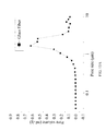
- FIG. 13 is a schematic diagram illustrating an embodiment of the proton conductivity of a proton exchange membrane varying with temperatures in accordance with FIG. 1 of the present disclosure.
- the proton exchange membrane of the present embodiment has better proton conductivity, and the proton conductivity reaches to 0.84 S/cm at a temperature of 150° C.
- the AC impedance analysis is applied to measure the proton conductivity.
- FIG. 14 is a schematic diagram illustrating a comparison and an embodiment of a proton exchange membrane in accordance with the present disclosure.
- the proton conductivity of the proton exchange membrane of an embodiment and that of the comparison are measured in one minute.
- the composition of the proton exchange membrane of the comparison is PTFE, phosphoric acid, and glass fiber processed with hydrophilic treatment.
- the hydrophilic treatment may include KOH immersion treatment, hydro plasma treatment or methanol immersion treatment, but it shall be not limited thereto.
- the proton exchange membrane of the embodiment is formed according to the process shown in FIG. 1 .
- the detailed data of FIG. 14 is shown in table 4.
- the proton conductivity of the proton exchange membrane of the embodiment after 1 minute is 32%, and the decrease of proton conductivity of the proton exchange membrane of the comparison after 1 minute is 35%.
- the degree of attenuation is 3%, meaning that the proton conductivity of the proton exchange membrane of the embodiment has a smaller decrease.
- the proton conductivity of the proton exchange membrane of the embodiment has a better capacity for retaining the phosphoric acid after a period of time.
- the initial proton conductivity of the proton exchange membrane of the embodiment is better than that of the comparison, indicating that the proton exchange membrane of the embodiment is able to retain more phosphoric acids which are served as proton conductor, so as to further promote the electrical efficiency of the fuel cell.
- FIGS. 15A and 15B are schematic diagrams illustrating an embodiment of the pore distribution of the glass fiber and the PTFE film, respectively.
- the pore distribution of the glass fiber is about 1 ⁇ m to about 1.5 ⁇ m
- the pore distribution of the PTFE film is about 50 nm to about 400 nm.
- the porosity of the glass fiber is about 93%
- the porosity of the PTFE film is about 70%.
- the above data were all measured by the mercury porosimeter.
- the difference of the pore size and the porosity between the substrate (e.g. the glass fiber) and the leak-proof film (e.g. the PTFE film) may facilitate to retain the phosphoric acid in the proton exchange membrane.
- the proton exchange membrane of the present disclosure is able to retain the phosphoric acid in organic/inorganic complex form and micron/nano complex pore size.
- the proton exchange membrane of the present disclosure has better proton conductivity and the proton conductivity can be maintained after a period of time, so that the electrical efficiency of fuel cell can be promoted completely.
- the contact angle, AFM, SEM, EDX and XPS are applied to validate the modification of the present disclosure, indicating that parameters such as contact angles, photos, chemical constitutions, bonding, and the relative strength of atoms, and so on all successfully achieve the desired effect after being modified.
Landscapes
- Chemical & Material Sciences (AREA)
- General Chemical & Material Sciences (AREA)
- Engineering & Computer Science (AREA)
- Manufacturing & Machinery (AREA)
- Life Sciences & Earth Sciences (AREA)
- Sustainable Development (AREA)
- Sustainable Energy (AREA)
- Chemical Kinetics & Catalysis (AREA)
- Electrochemistry (AREA)
- Dispersion Chemistry (AREA)
- Fuel Cell (AREA)
- Conductive Materials (AREA)
Abstract
A manufacturing method of a proton exchange membrane is provided, which includes the steps as follows. The hydroxyl groups are disposed on the surface of a substrate by a hydrophilic treatment. The hydroxyl groups on the substrate are chemically modified with a coupling agent by a sol-gel process. The substrate is exposed to an amino acid with a phosphonate radical so that the amino acid containing a phosphonate radical can be chemically bonded with the coupling agent. The chemically bonded substrate is immersed in phosphoric acid for absorbing the phosphoric acid. The substrate blended with the phosphoric acid is placed between at least two leak-proof films for the purpose of preventing the leakage of the absorbed phosphoric acid. The proton exchange membrane manufactured by this method enable to retain the phosphoric acid in organic/inorganic complex form and micron/nano complex pore size.
Description
This application claims the benefit of Taiwan Patent Application No. 104143558, filed on Dec. 24, 2015, in the Taiwan Intellectual Property Office, the disclosure of which is incorporated herein in its entirety by reference.
1. Field of the Invention
The present disclosure generally relates to a proton exchange membrane and manufacturing method thereof, and in particular, to a proton exchange membrane and manufacturing method thereof which is feasible to be applied to the phosphoric acid fuel cell (PAFC).
2. Description of the Related Art
Currently, the energies such as petroleum, electric power, and natural resources, and so on are globally available. The petroleum is conveniently to be used, and the petroleum consumption plays a striking figure in the world energy consumption by 78%. However, the great amount of petroleum consumption causes the considerable carbon emission, resulting that the greenhouse effect and climate change become uncontrollable, and ecocide and eco-catastrophe seem to be inevitable. As a consequence, developing green energy to replace petroleum is in dire need.
Countries have been actively developing the green energies such as hydrogen power, solar power, water power, wind power, and geothermal heat, and so on. The development of hydrogen power is most noticeable. The usage of hydrogen-oxygen fuel cell is highly efficient and eco-friendly because hydrogen gas and oxygen gas are served as fuels for the hydrogen-oxygen fuel cell to generate power and water through the electrochemical reaction. Hence, the hydrogen-oxygen fuel cell attracts attentions. Most PAFCs can be functioned at the temperature between 150 and 210° C. as the phosphoric acid which is anhydrous self-ionization in the temperature range is served as the proton conductor. Compared with the traditional proton exchange membrane fuel cell (PEMFC), the PAFC has following advantages. 1. The platinum catalyst is unease to be poisoned by CO, so that the platinum catalyst's carrying capacity is reduced to save the cost of battery assembly. 2. The technical problem of water management can be solved to simplify the design problem, so that the expenditure on humidifier becomes unnecessary. 3. The usage of energy is promoted. 4. The capacity of reforming gaseous fuel is provided to have a better tolerance for CO2. Nonetheless, the technical problem of PAFC is that the used proton exchange membrane is incapable of retaining the phosphoric acid after a period of time, so that the proton conductivity of the proton exchange membrane decreases and the overall efficiency of PAFC reduces accordingly. As a result, the retention capacity of the phosphoric acid for the proton exchange membrane has to be improved.
In view of the aforementioned technical problems, the objective of the present disclosure provides a proton exchange membrane which is able to retain the phosphoric acid in organic/inorganic complex form and micron/nano complex pore size to improve the retention capacity for the phosphoric acid.
In view of the aforementioned technical problems, the present disclosure provides a method of manufacturing a proton exchange membrane, which may include the steps as follows: disposing hydroxyl groups on a surface of a substrate by a hydrophilic treatment; chemically modifying the hydroxyl groups disposed on the substrate with a coupling agent by a sol-gel process; chemically bonding an amino acid containing a phosphonate radical with the coupling agent modifying the substrate; the substrate which is chemically bonded absorbing phosphoric acid; and placing the substrate blended with the phosphoric acid between at least two leak-proof films for preventing the leakage of the absorbed phosphoric acid.
Preferably, the substrate may include glass fiber, polybenzimidazoles (PBI), polyolefin, or polyacrylamide/polyvinyl alcohol (PAM/PVA).
Preferably, the coupling agent may include (3-glycidyloxypropyl)trimethoxysilane (GPTMS).
Preferably, the amino acid with a phosphonate radical may include O-phospho-DL-serine, O-phospho-L-threonine, O-phospho-L-tyrosine, or N-phosphonomethylgly cine.
Preferably, the least two leak-proof films may include a polytetrafluoroethylene (PTFE) film, a graphene oxide, or a polycarbonate membrane.
The present disclosure further provides a proton exchange membrane, which includes a substrate, a coupling agent, serine with a phosphonate radical, phosphoric acid and at least two leak-proof films. The coupling agent can be chemically modified on the substrate by a sol-gel process. The serine containing a phosphonate radical can be chemically bonded with the coupling agent. The phosphoric acid can be absorbed on the substrate. The substrate blended with the phosphoric acid is placed between the least two leak-proof films for preventing the leakage of the absorbed phosphoric acid.
Preferably, the substrate may include glass fiber, polybenzimidazoles, polyolefin, or polyacrylamide/polyvinyl alcohol.
Preferably, the coupling agent may include (3-glycidyloxypropyl)trimethoxysilane.
Preferably, the serine containing a phosphonate radical may include O-phospho-DL-serine, O-phospho-L-threonine, O-phospho-L-tyrosine, or N-phosphonomethylgly cine.
Preferably, the least two leak-proof films may include a polytetrafluoroethylene film, a graphene oxide, or a polycarbonate membrane.
As mentioned previously, a proton exchange membrane provided by the present disclosure is able to retain the phosphoric acid in organic/inorganic complex form to improve the retention capacity of the proton exchange membrane for retaining the phosphoric acid, such that the technical problem concerning the phosphoric acid leaking with time can be improved.
Please refer to FIGS. 1, 2A, 2B and 2C , which are flow charts of a method of manufacturing a proton exchange membrane in accordance with the present disclosure. The method of manufacturing a proton exchange membrane is feasible to be applied to all the embodiments of the present disclosure. In the present embodiment, the hydrophilic treatment may include KOH immersion treatment, hydro plasma treatment or methanol immersion treatment, but it shall be not limited thereto. The substrate may be made of glass fiber, polybenzimidazoles, polyolefin, or polyacrylamide/polyvinyl alcohol, but it shall be not limited thereto. The amino acid with a phosphonate radical may include O-phospho-DL-serine, O-phospho-L-threonine, O-phospho-L-tyrosine, or N-phosphonomethylglycine, but it shall be not limited thereto. As shown in FIG. 1 , the process may include the following steps.
Step 1: acetone, isopropanol and deionized water are used to clean a glass fiber 10 through supersonic vibration by 5 minutes, and then the glass fiber 10 is immersed in the potassium hydroxide (KOH) solution of 10% concentration at room temperature through supersonic vibration by 40 minutes, such that the glass fiber 10 is cleaned and has hydrophilic effect. As shown in FIG. 2A , the glass fiber 10 made according to the process mentioned above has hydroxyl groups. The following reaction is shown as follows.
Step 2: 3-glycidoxypropyl-trimethoxysilane (GPTMS) is disposed on the glass fiber 10 by a sol-gel process. The GPTMS is added dropwise to ethanol to prepare the GPTMS in ethanol solution of 1 vol. %, and then a magnetic stirrer is sued to stir the solution. The addition of acetic acid is used to adjust the PH value of the solution to be 3 to 5, and acid catalysis is used to facilitate the hydrolysis of the GPTMS. The glass fiber 10 processed with hydrophilic treatment is added to the prepared GPTMS solution to perform dehydration reaction by 4 hours. The step facilitates the GPTMS to be disposed on the glass fiber 10, as shown in FIG. 2B .
Step 3: O-phospho-DL-serine of 2 grams is solved in the deionized water with 200 ml at a temperature of 80° C. The glass fiber 10 disposed with the GPTMS is placed in the O-phospho-DL-serine solution at a temperature of 80° C. to react by one hour. The step is to perform the ring-opening and grafting reaction by using epoxy group of the GPTMS and amino group of the O-phospho-DL-serine, so as to achieve the purpose of chemically bonding phosphonate radicals on the glass fiber 10, as shown in FIG. 2C .
Step 4: the prepared glass fiber 10 is immersed in the phosphoric acid of 86% concentration at a temperature of 150° C. by 20 minutes, and baked at a temperature of 60° C. to remove the unwanted water. Afterwards, the glass fiber 10 is placed between two polytetrafluoroethylene films to form the desired proton exchange membrane of the present disclosure. The polytetrafluoroethylene film used herein is to prevent the leakage of the phosphoric acid absorbed by the glass fiber 10.
In accordance with the present embodiment, the proton exchange membrane transfers proton in organic/inorganic complex form. The organic form means that the proton is transferred by the phosphonate radicals chemically bonded (containing C—P bond) on the substrate. The inorganic form is that the proton is transferred through electrolyte such as the phosphoric acid adhered to the substrate by capillary action, Van der Waals force, or hydrogen bond. The organic/inorganic complex form is characterized of better proton conductivity due to the inorganic form and stronger C—P bonding that performs by the organic form. Besides, it can avoid losing electrolyte resulted from the inorganic form. As a result, the defect of the proton conductivity degrading with time can be improved.
The sequence shown in FIG. 1 explains the process of substrate. For example, when the substrate is modified by the GPTMS, that means the substrate has also been processed with the hydrophilic treatment, or when the substrate is processed with ring-opening and grafting reaction, that means the substrate has also been processed by the hydrophilic treatment and modified by the GPTMS, the unnecessary details are no longer provided hereinafter for the concise manner.
Please refer to FIGS. 3A through 3E , which are the photos of an embodiment of the silicon wafer in accordance with the present disclosure. The reason the silicon wafer is used to instead of the glass fiber in this assay is that the glass fiber is too soft to be analyzed for detecting the contact angle, so that the silicon wafer which has identical composition to glass fiber is selected as a replacement. Here, the silicon wafer shown in FIG. 3A is unprocessed and has a contact angle of 28°. The silicon wafer in FIG. 3B is processed with hydrophilic treatment through the KOH solution and has a contact angle of 3°. The silicon wafer shown in FIG. 3C reacts with the GPTMS by 2 hours and has a contact angle of 22°. The silicon wafer shown in FIG. 3D reacts with the GPTMS by 3 hours and has a contact angle of 38°. The silicon wafer shown in FIG. 3E reacts with the GPTMS by 4 hours and has a contact angle of 42°.
According to the results derived from the processes mentioned above, it can be found that the silicon wafer processed with hydrophilic treatment through the KOH solution has a contact angle from 28° to 3°, proving that the hydrophilic treatment processed with the KOH solution does have hydrophilic effect. When the silicon wafer processed with hydrophilic treatment reacts with the GPTMS, the contact angle varies with time from 3° to 42°. Therefore, it can be found that the GPTMS is successfully disposed on the silicon wafer, achieving the effect of modifying the surface of the silicon wafer.
Please refer to FIG. 4A and FIG. 4B , which are the top view and side view of structural model of AFM surface of the silicon wafer, respectively. The reason the silicon wafer is used to instead of the glass fiber in this assay is that the glass fiber is too soft to be analyzed by AFM, so that the silicon wafer which has identical composition to glass fiber is selected as a replacement. Here, the silicon wafers respectively shown in FIGS. 4A and 4B are both processed with hydrophilic treatment and then react with the GPTMS by 3 hours.
According to the aforementioned figures it can be found that surfaces of silicon wafers have a maximum loss by 1 nm, indicating that the GPTMS is evenly disposed on the silicon wafers to form the film of a nano size after the reaction.
Please refer to FIG. 5 , which is the SEM photo showing an embodiment the substrate of the proton exchange membrane processed with hydrophilic treatment in accordance with the present disclosure. In the present embodiment, the substrate may include glass fiber, and hydrophilic treatment may be performed by KOH solution, but it shall be not limited thereto. Here, by means of hydrophilic treatment, the glass fiber has hydroxyl groups and is further combined with the GPTMS, enabling the GPTMS to be disposed on the glass fiber.
Please refer to FIG. 6 , which is the SEM photo showing an embodiment of the substrate of the proton exchange membrane processed with the GPTMS in accordance with the present disclosure. In the present embodiment, the substrate may include glass fiber, but it shall be not limited thereto. Comparing FIG. 6 with FIG. 5 can find a minor difference. However, as the two figures are both of a nano size, it proves that the GPTMS is disposed on the glass fiber with a nano size.
Please refer to FIGS. 7A and 7B , which are respectively a SEM photo and an EDX chemical constitution analytical diagram showing another embodiment of the substrate of the proton exchange membrane modified by the GPTMS in accordance with the present disclosure. In the embodiment, the substrate may include glass fiber, but it shall be not limited thereto. The EDX chemical constitution of FIG. 7B is shown in table 1.
| TABLE 1 | ||
| Element | Weight (%) | Atomic (%) |
| C | 11.14 | 15.94 |
| O | 62.42 | 67.07 |
| Na | 5.64 | 4.22 |
| Al | 1.60 | 1.02 |
| Si | 19.20 | 11.75 |
| Totals | 100.00 | 100.00 |
As the table shows, the glass fiber without C atom has a weight percent of about 11% and an atom percentage of about 16%. The performance of the GPTMS containing C atom disposed on the glass fiber is therefore found. As a result, the data indicates that the GPTMS is successfully disposed on the glass fiber.
Please refer to FIG. 8A and FIG. 8B , which are respectively a XPS diagram of the substrate processed with hydrophilic treatment and a XPS diagram of the substrate modified by the GPTMS. In the present embodiment, the substrate may include glass fiber, but it shall be not limited thereto. As shown in the figures, after being modified by the GPTMS, the relative strength of C—C bond and C—H bond increases from 2000 C/S as shown in FIG. 8A to 4300 C/S as shown in FIG. 8B , and the relative strength of C—H—C bond increases from 1600 C/S as shown in FIG. 8A to 4000 C/S as shown in FIG. 8B .
As the data shows, after the glass fiber is modified by the GPTMS, the relative strength of C—C bond, C—H bond and C—H—C bond of the GPTMS increases, meaning that the bonding number increases. Hence, it proves that the GPTMS is indeed disposed on the glass fiber.
Please refer to FIG. 9A and FIG. 9B , which are respectively a XPS diagram of the substrate of the proton exchange membrane modified by the GPTMS and a XPS diagram showing the ring-opening and grafting reaction of the substrate containing phosphonate radicals. In the present embodiment, the substrate may include glass fiber and the amino acid with a phosphonate radical may include O-phospho-DL-serine, but it shall be not limited thereto. As shown in the figures, after the ring-opening and grafting reaction, the relative strength of nitrogen element increases from 0 C/S as shown in FIG. 9A to 1.23 C/S as shown in FIG. 9B , and the relative strength of phosphor element increases from 0 C/S as shown in FIG. 9A to 1.34 C/S as shown in FIG. 9B .
As the data shows, after the ring-opening and grafting reaction, the relative strength of nitrogen element and phosphor element of O-phospho-DL-serine increase from 0 as shown in FIG. 9A to a certain strength as shown in FIG. 9B . Hence, it shows that the GPTMS is indeed disposed on the glass fiber.
Please refer to FIG. 10 , which is a SEM photo showing the proton exchange membrane and the substrate exposed to the amino acid with a phosphonate radical after the ring-opening and grafting reaction. In the present embodiment, the substrate may include glass fiber and the amino acid with a phosphonate radical may include O-phospho-DL-serine, but it shall be not limited thereto. The difference between FIG. 5 , FIG. 6 and FIG. 10 lies that there are numerous plate-shaped substances of nano size disposed among the glass fibers shown in FIG. 10 , compared the substrate processed with hydrophilic treatment shown in FIG. 5 and the substrate modified by the GPTMS shown in FIG. 6 . The chemical constitution of the plate-shaped substances will be described in the following paragraphs.
Please refer to FIG. 11A and FIG. 11B , which are respectively a SEM photo showing the substrate of the proton exchange membrane exposed to the amino acid with a phosphonate radical after ring-opening and grafting reaction and an analytical diagram of EXD chemical constitution thereof. In the present embodiment, the substrate may include glass fiber and the amino acid with a phosphonate radical may include O-phospho-DL-serine, but it shall be not limited thereto. The EDX chemical constitution of FIG. 11B is shown in table 2.
| TABLE 2 | ||
| Element | Weight (%) | Atomic (%) |
| C | 22.96 | 30.33 |
| N | 3.95 | 4.48 |
| O | 57.62 | 57.14 |
| Al | 0.28 | 0.17 |
| Si | 2.02 | 1.14 |
| P | 13.16 | 6.74 |
| Totals | 99.99 | 100 |
Compared with table 1 it can be found that the carbon element is not present in O-phospho-DL-serine before the ring-opening and grafting reaction, while it has a weight percentage of about 13% and an atom percentage of about 7% after the reaction. As a result, the data indicates that the O-phospho-DL-serine is successfully bonded on the glass fiber.
Please refer to FIG. 12A and FIG. 12B , which are respectively a SEM photo showing the substrate of the proton exchange membrane exposed to the amino acid with a phosphonate radical after ring-opening and grafting reaction and an analytical diagram of EXD chemical constitution thereof. In the present embodiment, the substrate may include glass fiber and the amino acid with a phosphonate radical include O-phospho-DL-serine, but it shall be not limited thereto. The EDX chemical constitution of FIG. 12B is shown in table 3.
| TABLE 3 | ||
| Element | Weight (%) | Atomic (%) |
| C | 24.27 | 32.32 |
| O | 58.86 | 58.84 |
| Si | 2.63 | 1.50 |
| P | 14.23 | 7.35 |
| Totals | 99.99 | 100.01 |
As the data shows, the P element, which is derived from the plate in SEM photo, shown in table 3 has a higher weight percentage of about 1% and a higher atomic percentage of about 0.6% than that in table 2. Hence, it can be found that the plates are the main place where O-phospho-DL-serine reacts with glass fiber.
Please refer to FIG. 13 , which is a schematic diagram illustrating an embodiment of the proton conductivity of a proton exchange membrane varying with temperatures in accordance with FIG. 1 of the present disclosure. As shown in the figure, the proton exchange membrane of the present embodiment has better proton conductivity, and the proton conductivity reaches to 0.84 S/cm at a temperature of 150° C. Here, the AC impedance analysis is applied to measure the proton conductivity.
| TABLE 4 | |
| Types of the proton | |
| exchange membranes | |
| Test types | Embodiment | Comparison |
| Proton conductivity (S/cm) | 0.83 | 0.71 |
| Proton conductivity after 1 min (S/cm) | 0.56 | 0.46 |
| Decrease of Proton conductivity after 1 min | 32% | 35% |
According to the result shown in table 4 it can be found that the proton conductivity of the proton exchange membrane of the embodiment after 1 minute is 32%, and the decrease of proton conductivity of the proton exchange membrane of the comparison after 1 minute is 35%. The degree of attenuation is 3%, meaning that the proton conductivity of the proton exchange membrane of the embodiment has a smaller decrease. In other words, the proton conductivity of the proton exchange membrane of the embodiment has a better capacity for retaining the phosphoric acid after a period of time. In addition, the initial proton conductivity of the proton exchange membrane of the embodiment is better than that of the comparison, indicating that the proton exchange membrane of the embodiment is able to retain more phosphoric acids which are served as proton conductor, so as to further promote the electrical efficiency of the fuel cell.
Please refer to FIGS. 15A and 15B , which are schematic diagrams illustrating an embodiment of the pore distribution of the glass fiber and the PTFE film, respectively. As shown in the figure, the pore distribution of the glass fiber is about 1 μm to about 1.5 μm, and the pore distribution of the PTFE film is about 50 nm to about 400 nm. In addition, the porosity of the glass fiber is about 93%, and the porosity of the PTFE film is about 70%. The above data were all measured by the mercury porosimeter. The difference of the pore size and the porosity between the substrate (e.g. the glass fiber) and the leak-proof film (e.g. the PTFE film) may facilitate to retain the phosphoric acid in the proton exchange membrane.
In conclusion, after the modified processes, the proton exchange membrane of the present disclosure is able to retain the phosphoric acid in organic/inorganic complex form and micron/nano complex pore size. Compared with the traditional proton exchange membrane which retains the phosphoric acid in inorganic form, the proton exchange membrane of the present disclosure has better proton conductivity and the proton conductivity can be maintained after a period of time, so that the electrical efficiency of fuel cell can be promoted completely. In addition, the contact angle, AFM, SEM, EDX and XPS are applied to validate the modification of the present disclosure, indicating that parameters such as contact angles, photos, chemical constitutions, bonding, and the relative strength of atoms, and so on all successfully achieve the desired effect after being modified.
While the means of specific embodiments in present disclosure has been described by reference drawings, numerous modifications and variations could be made thereto by those skilled in the art without departing from the scope and spirit of the invention set forth in the claims. The modifications and variations should in a range limited by the specification of the present disclosure.
Claims (3)
1. A method of manufacturing a proton exchange membrane, comprising the following steps of:
disposing hydroxyl groups on a surface of a substrate by a hydrophilic treatment;
chemically modifying the hydroxyl groups disposed on the substrate with a coupling agent by a sol-gel process;
chemically bonding an amino acid containing a phosphonate radical with the coupling agent chemically modifying the substrate;
making the substrate which is chemically bonded to absorb phosphoric acid; and
placing the substrate blended with the phosphoric acid between at least two leak-proof films for preventing the leakage of the absorbed phosphoric acid,
wherein the coupling agent comprises (3-glycidyloxypropyl)trimethoxysilane, and the amino acid containing a phosphonate radical comprises O-phospho-DL-serine, O-phospho-L-threonine, O-phospho-L-tyrosine, or N-phosphonomethylglycine.
2. The method of manufacturing the proton exchange membrane of claim 1 , wherein the substrate comprises glass fiber, polybenzimidazoles, polyolefin, or polyacrylamide/polyvinyl alcohol.
3. The method of manufacturing the proton exchange membrane of claim 1 , wherein the least two leak-proof films comprise a polytetrafluoroethylene film, a graphene oxide, or a polycarbonate membrane.
Applications Claiming Priority (3)
| Application Number | Priority Date | Filing Date | Title |
|---|---|---|---|
| TW104143558 | 2015-12-24 | ||
| TW104143558A | 2015-12-24 | ||
| TW104143558A TWI564325B (en) | 2015-12-24 | 2015-12-24 | Proton exchange membrane and manufacturing method thereof |
Publications (2)
| Publication Number | Publication Date |
|---|---|
| US20170187058A1 US20170187058A1 (en) | 2017-06-29 |
| US10276885B2 true US10276885B2 (en) | 2019-04-30 |
Family
ID=58407754
Family Applications (1)
| Application Number | Title | Priority Date | Filing Date |
|---|---|---|---|
| US15/097,015 Active 2037-02-13 US10276885B2 (en) | 2015-12-24 | 2016-04-12 | Proton exchange membrane and manufacturing method thereof |
Country Status (2)
| Country | Link |
|---|---|
| US (1) | US10276885B2 (en) |
| TW (1) | TWI564325B (en) |
Families Citing this family (3)
| Publication number | Priority date | Publication date | Assignee | Title |
|---|---|---|---|---|
| CN110649302A (en) * | 2019-09-27 | 2020-01-03 | 大连大学 | Method for enhancing phosphoric acid doping degree of polybenzimidazole membrane |
| CN114824393B (en) * | 2021-01-29 | 2024-01-30 | 武汉氢阳能源有限公司 | Quaternary amine salt composite proton exchange membrane and preparation method thereof |
| CN116544428B (en) * | 2023-04-18 | 2024-12-24 | 东风汽车集团股份有限公司 | A composite material and its preparation method and application |
Citations (6)
| Publication number | Priority date | Publication date | Assignee | Title |
|---|---|---|---|---|
| US20060068204A1 (en) * | 2004-09-30 | 2006-03-30 | 3M Innovative Properties Company | Substrate with attached dendrimers |
| US20060154127A1 (en) * | 2003-09-30 | 2006-07-13 | Canon Kabushiki Kaisha | Membrane electrode assembly, production method for the same, and proton-exchange membrane fuel cell |
| US20070048592A1 (en) * | 2005-08-29 | 2007-03-01 | Industrial Technology Research Institute | Composition, complex and method for enhancing catalysts utilization |
| US20070154760A1 (en) * | 2005-12-30 | 2007-07-05 | Yimin Zhu | Composite polymer electrolyte membranes and electrode assemblies for reducing fuel crossover in direct liquid feed fuel cells |
| US20080286628A1 (en) * | 2005-10-27 | 2008-11-20 | Wacker Chemie Ag | Particles Comprising Zwitterionic Structural Elements |
| US20100040927A1 (en) * | 2006-10-06 | 2010-02-18 | Masaru Yoshida | Silane crosslinked structure-introduced fuel-cell polymer electrolyte membrane and fuel-cell electrode assembly having the same |
Family Cites Families (3)
| Publication number | Priority date | Publication date | Assignee | Title |
|---|---|---|---|---|
| CN103531831B (en) * | 2013-08-16 | 2015-09-30 | 武汉理工大学 | Temperature proton exchange film material and preparation method thereof in a kind of soda acid type aminopolyphosphonic acid polysiloxanes |
| CN105037733B (en) * | 2015-05-29 | 2017-11-17 | 武汉理工大学 | A kind of phosphoric acid radical siloxane high temperature proton exchange film of hydrolysis-stable and preparation method thereof |
| CN105098215B (en) * | 2015-08-19 | 2017-05-31 | 武汉理工大学 | A kind of phosphonic acids radical siloxane PEM of hydrolysis-stable and preparation method thereof |
-
2015
- 2015-12-24 TW TW104143558A patent/TWI564325B/en active
-
2016
- 2016-04-12 US US15/097,015 patent/US10276885B2/en active Active
Patent Citations (6)
| Publication number | Priority date | Publication date | Assignee | Title |
|---|---|---|---|---|
| US20060154127A1 (en) * | 2003-09-30 | 2006-07-13 | Canon Kabushiki Kaisha | Membrane electrode assembly, production method for the same, and proton-exchange membrane fuel cell |
| US20060068204A1 (en) * | 2004-09-30 | 2006-03-30 | 3M Innovative Properties Company | Substrate with attached dendrimers |
| US20070048592A1 (en) * | 2005-08-29 | 2007-03-01 | Industrial Technology Research Institute | Composition, complex and method for enhancing catalysts utilization |
| US20080286628A1 (en) * | 2005-10-27 | 2008-11-20 | Wacker Chemie Ag | Particles Comprising Zwitterionic Structural Elements |
| US20070154760A1 (en) * | 2005-12-30 | 2007-07-05 | Yimin Zhu | Composite polymer electrolyte membranes and electrode assemblies for reducing fuel crossover in direct liquid feed fuel cells |
| US20100040927A1 (en) * | 2006-10-06 | 2010-02-18 | Masaru Yoshida | Silane crosslinked structure-introduced fuel-cell polymer electrolyte membrane and fuel-cell electrode assembly having the same |
Also Published As
| Publication number | Publication date |
|---|---|
| TWI564325B (en) | 2017-01-01 |
| US20170187058A1 (en) | 2017-06-29 |
| TW201723040A (en) | 2017-07-01 |
Similar Documents
| Publication | Publication Date | Title |
|---|---|---|
| US8911919B2 (en) | Local hydrophilic gas diffusion layer and fuel cell stack comprising the same | |
| CN101087029B (en) | Solid polymer electrolyte membrane, membrane electrode assembly, and fuel cell using the same | |
| CN103762375B (en) | Politef interlayer protection ion exchange membrane, its preparation method and flow battery | |
| CN111063925A (en) | Catalyst coated membrane, fuel cell and method of making | |
| CN111413255B (en) | Microelectrode system and method for testing oxygen mass transfer coefficient of proton exchange membrane | |
| WO2021136148A1 (en) | Gas diffusion layer, preparation method therefor, membrane electrode assembly, and fuel cell | |
| US10276885B2 (en) | Proton exchange membrane and manufacturing method thereof | |
| CN102321265B (en) | Method for preparing proton exchange membranes from modified bacterial cellulose membranes and application thereof | |
| US8278012B2 (en) | Membrane electrode assembly for fuel cell, and fuel cell system including the same | |
| CN111584879B (en) | Gas diffusion layer, method for producing same, and corresponding membrane electrode assembly and fuel cell | |
| CN103035934B (en) | Water vapor transport membrane | |
| CN100505395C (en) | A kind of preparation method of self-humidifying proton exchange membrane fuel cell membrane electrode | |
| JP2008510064A (en) | Fuel composition | |
| KR20140129721A (en) | Proton exchange membrane for fuel cell, preparation method thereof and fuel cell comprising the same | |
| CN101320812A (en) | Method for preparing proton exchange fuel cell membrane electrode adopting bacteria cellulose | |
| CN102881754A (en) | Back point contact cell with bubbling-free aluminum oxide and preparation method thereof | |
| JP5870643B2 (en) | Manufacturing method of membrane electrode assembly for polymer electrolyte fuel cell | |
| CN118352583A (en) | Method for preparing porous proton exchange membrane for flow battery by using acid etching technology | |
| CN113130929B (en) | Method for reducing resistance of silicon-based bipolar plate, silicon-based bipolar plate and fuel cell | |
| CN1263179C (en) | Process for preparing proton composite exchange membrane for high temperature proton exchange membrane fuel battery | |
| RU2373990C2 (en) | Composite proton-conducting membrane and method of its manufacturing | |
| CN105158119A (en) | Porous membrane gas diffusion coefficient testing apparatus | |
| CN102969519B (en) | A kind of fuel cell humidifier | |
| CN102002167A (en) | Proton exchange membrane applied to direct methanol fuel cell and preparation method thereof | |
| CN221900040U (en) | Gas diffusion layer structure and fuel cell |
Legal Events
| Date | Code | Title | Description |
|---|---|---|---|
| AS | Assignment |
Owner name: NATIONAL TSING HUA UNIVERSITY, TAIWAN Free format text: ASSIGNMENT OF ASSIGNORS INTEREST;ASSIGNORS:TSENG, FAN-GANG;WANG, PEN-CHENG;CHIU, YU-TING;REEL/FRAME:038320/0018 Effective date: 20160321 |
|
| STPP | Information on status: patent application and granting procedure in general |
Free format text: PUBLICATIONS -- ISSUE FEE PAYMENT VERIFIED |
|
| STCF | Information on status: patent grant |
Free format text: PATENTED CASE |
|
| MAFP | Maintenance fee payment |
Free format text: PAYMENT OF MAINTENANCE FEE, 4TH YR, SMALL ENTITY (ORIGINAL EVENT CODE: M2551); ENTITY STATUS OF PATENT OWNER: SMALL ENTITY Year of fee payment: 4 |