US1027361A - Heel compressing and loading apparatus. - Google Patents
Heel compressing and loading apparatus. Download PDFInfo
- Publication number
- US1027361A US1027361A US11793502A US1902117935A US1027361A US 1027361 A US1027361 A US 1027361A US 11793502 A US11793502 A US 11793502A US 1902117935 A US1902117935 A US 1902117935A US 1027361 A US1027361 A US 1027361A
- Authority
- US
- United States
- Prior art keywords
- heel
- nail
- nails
- carrier
- block
- Prior art date
- Legal status (The legal status is an assumption and is not a legal conclusion. Google has not performed a legal analysis and makes no representation as to the accuracy of the status listed.)
- Expired - Lifetime
Links
- 230000002459 sustained effect Effects 0.000 description 13
- 239000004020 conductor Substances 0.000 description 10
- 230000000994 depressogenic effect Effects 0.000 description 7
- 230000007246 mechanism Effects 0.000 description 7
- 238000010276 construction Methods 0.000 description 4
- 241001640117 Callaeum Species 0.000 description 3
- 239000010985 leather Substances 0.000 description 3
- 230000006835 compression Effects 0.000 description 2
- 238000007906 compression Methods 0.000 description 2
- 230000000694 effects Effects 0.000 description 2
- 230000005484 gravity Effects 0.000 description 2
- 238000007373 indentation Methods 0.000 description 2
- 101000794560 Arbacia punctulata Calmodulin-beta Proteins 0.000 description 1
- 229910001018 Cast iron Inorganic materials 0.000 description 1
- 241001656823 Ornithostaphylos Species 0.000 description 1
- 229910000831 Steel Inorganic materials 0.000 description 1
- 230000015572 biosynthetic process Effects 0.000 description 1
- 210000000481 breast Anatomy 0.000 description 1
- 239000000463 material Substances 0.000 description 1
- 238000000465 moulding Methods 0.000 description 1
- 239000010959 steel Substances 0.000 description 1
Images



Classifications
-
- A—HUMAN NECESSITIES
- A43—FOOTWEAR
- A43D—MACHINES, TOOLS, EQUIPMENT OR METHODS FOR MANUFACTURING OR REPAIRING FOOTWEAR
- A43D33/00—Machines for assembling lifts for heels
- A43D33/04—Nailing machines for building the heels from lifts
Definitions
- the machine which is hereinshown and described as embodying this invention is a machine for inserting or loading nails in heel blanks, which blanks are also com pressed by the same machine and are subsequently attached to the shoe on a heel at taching machine. It should be understood, however, that many features of the invention are equally well applicable to heel attaohing machines which are employed to secure to shoes heels which have not previously been loaded.
- the nails hitherto used on these machines have been tapered nails, larger at their heads than at their points and, with their heads substantially square. These nails have been chiefly used in what is called blind nailing, in which use the nails are left pro-. truding somewhat when the heel is attached to the shoe and on which protruding heads the top lift is afterward spanked.
- blind nailing in which use the nails are left pro-. truding somewhat when the heel is attached to the shoe and on which protruding heads the top lift is afterward spanked.
- surface nailing that is, the class of work in which the nails are visible on the tread surface of the heel, it has been cheap work in which the appearance of the nails on the tread surface of the heel was not important.
- the present machine is particularly intended for use in driving English slug nails, or nails whose heads are oblong instead of being square.
- the nails must also be directed in their movement between the pockets referred to and the nail block in such way that they will be restrained from free axial rotation, and to accomplish this I have connected with said pockets nail tubes or conductors having nail passages of a thickness less than the width of the nail.
- the heel In machines for loading or inserting nails into heels, the heel is usually prioked by awls before the nails are driven therein.
- the awls commonly employed for this purpose are tapered at their ends to present a central point. I find that the hole made by an awl having a central point is not well when forced into a compressed heel is to make a hole which curves toward the edge of the heel instead of passing straight into it, because that is the path of least resistance.
- a nail driven into leather tends to force the leather in contact with the sides of the nail down in the direction in which the nail is being driven, and when the nail is fully driven so that its head is flush with the general surface of the work, the surface of the work immediately around the nail has become depressed so that a concavity is formed.
- the awls tend to de press the material of the walls of the awlholes in the same manner that the nail does when it is driven. It has been customary in view of this fact to drive the nails into the holes until their heads were somewhat below the general surface of the heel, in order to position the head of the nail flush with the depressed portion of the work immediately surrounding the nail.
- the said registering or positioning plate has at its under side a groove to receive the rib, or it may be a row of projections, which has been formed on the face of the heel by the templet.
- the registering plate is also provided with stops or gages to determine the position of the blank.
- the gate and the registering plate being carried by the nail block, said nail block and these parts may be removed together from the usual movable carrier when it is desired to provide for inserting nails into heels of a different size, or into heels in which the nails are to be difi'erently arranged.
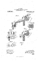
- Figure 1 in side elevation represents my improvements applied in one of the best forms now known to me, to a well known form of machine for automatically assorting nails and loading them into compressed heels.
- Fig. 2 is a partial vertical section of Fig. 1 to show the awl carrier, some of the awls, the templet, the heel-seat die to contact with the inner end of the heel, the driver, the driver guide, and the carrier sustaining some of the nail blocks;
- Fig. 3 in section on a larger scale shows a nail controller forming part of a nail assorting mechanism of well known construction, together with a means for turning the nails axially to a predetermined relative position so that said nails may enter properly'the pockets and tubes for guiding them to the nail block;
- Fig. 1 in side elevation represents my improvements applied in one of the best forms now known to me, to a well known form of machine for automatically assorting nails and loading them into compressed heels.
- Fig. 2 is a partial vertical section of Fig. 1 to show the
- FIG. 3 a cross sectional detail in the dotted line 3, Fig. 3, showing the shape of the chambers m;
- Fig. 4 is a view looking at Fig. 3 from the left, some of the parts shown in said figure being removed;
- Fig. 5 shows .the nail controller of Fig. 3 in a different position;
- Fig. 6 is a view of the part below the dotted line 00, Fig. 4, the screw being in section;
- Fig. 7 is a cross section of a nail conductor or tube;
- Fig. 8 is a detail on an enlarged scale showing in top view the carrier for the nail blocks, one block being wholly omitted and other nail blocks being illustrated differently to aid in disclosing their construction;
- Fig. 9 is a section of the parts shown in Fig.
- FIG. 16 is an underside view of the templet; Fig. 16 shows a modified form of templet, and Fig. 16 a section thereof in the lines; Fig. 17 a section of the templet in the line 02 Fig. 18 shows the nails fully driven into the heel as they will be when attaching the heel to a sole; Fig. 19 shows the heelaft-er the rib has been ground away; Fig. 20 shows the awl in two views and section; Fig. 21 shows a heel wherein'the heads of the nails are driven below the level of the face of'the heel as now commonly practiced; Fig. 22 shows an English slug nail in side view and cross section.
- the framework A of suitable shape contains a power shaft A havin a pinion A engaging a toothed gear A asto-n and rotating the main shaft A, said shaft actuating the awl carrier 39 provided with a plate t to sustain the awls to be described.
- the templet carrier Gr having secured to it by a suitable screw the novel templet to be described, the heel-seat dies E to sustain the ends of the heels 29 which are to contact with the sole of the boot; the heel holder 212 carried by the spring sustained spindle 213, the blocks C the eccentric 225, see Fig.
- the upper end of the framework A supports a frame A that sustains a horizontally reciprocating nail assorting apparatus comprising a hopper I) having leading from it suitable raceways 0, 0*, at the lower end of which is a lifter f having grooves that receive the endmost nails in the series of raceway grooves.
- the lifter is elevated at desired times by a cam f to enable the nails thereon to slide into grooves of a delivery portion h, the nails sliding therefrom by gravity.
- the nails having their heads'leading enter the chambers 117/, see Figs. 3 and 3 of a nail controller m, but the nails with their points leading meet the walls n of said chambers, as shown by dotted lines Fig. 3, and are arrested thereby but do not leave the delivery portion it.
- the shaft of the controller m is provided with a pinion m that is actuated by a lever m deriving its movement from a suitable cam on a shaft sustained in the frame A and actuated at intervals when it is desired to discharge a series of nails.
- the nails entering the nail controller in the Patent No. 577,213, were substantially square in cross section, and were discharged immediately from the controller into pockets, and thence directly into suitable tubes or conductors. It will not answer to discharge the English slug nail immediately into pockets or conductors without first axially asserting them, 2'. e. arranging them as to their sides to place their like sides all in the same relative position, so that they may enter the pockets and tubes under the same conditions in order that the nails may be loaded or driven into the heel blanks with their sides facing.
- the nails leave the chambers m with their fiat sides in substantially a horizontal plane, and as they enter the V-shaped grooves 6* they in settling in said grooves will be turned more or less transversely of their axes, and will travel along said grooves in the direction of the arrow, Fig. 3, and one of the sides of each nail will be sustained by one wall of the groove, and the edge of the nail will be sustained by the other wall of the groove, leaving the opposite edge of the nail not sustained by a wall partially upturned.
- each nail enters each pocket in the same way, the sides of each nail lying next the Walls 61*, see Fig. 4, of each of said pockets.
- the sides of the pockets at the lower end of the secondary raceway a are closed by a plate e held in place by screws 12.
- the underside of the downward extension of the secondary raceway a has a supporting plate h connected therewith by screws 9*.
- the plate has a series of lots i and a portion of the edges of each slot is cut away as at 76* to receive suitable shoulders Z at the top ends of the upper members 13 of the tubes or conductors employed to lead the nails to the foot 9
- the upper members 13 of the conducting tubes are flattened or shaped to present a throat narrower in width than the width of the nail, whereby the nails entering the tubes or conductors, as shown in Fig. 7, are prevented from turning therein, are all guided accurately, and arrive at the foot g with their sides facing in the line of driving.
- each tube or conductor is flexible to permit the lower ends of the tubes to be positioned in the nail foot in accordance with the desired arrangement of the nail holes in said foot, and the conductors are also capable of being twisted so as to deliver the nails with the wide sides of the adjacent nails contiguous or extending transversely of the line in which the series of nails is being driven.
- the templet G is provided with a groove 1 1,see Figs. 1 1, 16 and 17 ,cxtending in the line in which the series of nails are to be driven.
- the templet is provided with awl holes, the lower ends of which enter the groove 14.
- This templet with the exception of the groove referred to, is the same as the templet employed in Patent No. 502,667, above mentioned.
- awl t see Fig. 20, where the awl is shown enlarged in side and edge elevation and also in section.
- the awl corresponds in cross section substantially to the cross sectional shape of the nail to be driven.
- the awls are beveled at their outer ends as represented in Fig. 20 leaving a cutting edge in line with the inner edge of the awl rather than with the outer edge thereof.
- An awl such as herein illustrated'when thrust into the stock can not run outwardly toward the edge of the heel or in a direction outside or away from the line in which the awls penetrate the heel, the direction in which there is less stock and in which the stock might possibly yield. Any tendency of the awl t0 slant toward the center of the heel'is resisted by the entire body of the heel within the line of the awl holes, and consequently an awl such as herein shown will make a straight hole in the stock.
- Awls having a central point are sometimes deflected sufiiciently to cause the nail when driven into the awl hole to pass out of the heel seat end of the heel so close to the edge of the margin as to be exposed inthe finished shoe. This difiiculty is entirely overcome by forming the awl as hereinabove described.
- the nails are loaded or partially driven into the awl holes by drivers 0 fully described in said Patent No. 543,804, and later, when the said nails are fully driven through the heels to attach them to the soles 18 of boots and shoes, the heads of said nails enter the awl holes and lie a very little below the general level of the surface of the heel which is being attached and when the heel is subsequently buifed or finished it is necessary to grind off only the rib 17 and enough of the stock of the top-lift to remove the grain therefrom, if it is desired that the grain shall be removed from the top-lift.
- the carrier f mounted on the spindle A has a series of recesses 19 at its top side, see
- Each face plate and nail block has a central hole 23 which receives a hollow hub 24 of a circular gate 25.
- the face plate has a series of elongated nail holes 26 the side walls of which are beveled to aid in positioning the nails.
- the nail block 20 has nail holes of like shape.
- the gate is shown as a plate having a series of holes 27 for the passage therethrough of the nails to be driven into the heel blank.
- hub 24 has coacting with it a suitable spring 28 which acts normally to maintain the gate in such relation to the holes 26 in the face side by suitable screws 30 a registering plate 31 the edge of which next the hub of the carrier f is shaped to fit said carrier and prevent the rotation of the nail blockin the carrier.
- the plate 31 has a groove 31 to receive the rib 17 of the heel.
- the nail block and face plate 21 are connected rigidly together by the screws 22 and may be handled as one piece.
- the registering plate 31 has a series of nail holes in line with the holes in the nail block, and the gate is located in the space between the'underside of the nail block and the upper side of the registering plate 31. To enable the nails to be discharged from the nail block and be driven into the heel the gate must be rotated- To do this the driver plate has a stem 33, see Figs. 2, 9
- gages 35 shown by dotted lines in Fig. 8 and by full lines in Figs. 2,9 and 12, to contact with the edges of the heel along its sides and with the breast of the heel.
- the gages referred to are held fixedly in operative position by means of screws 36 which are extended through wings of the gages and enter threaded holes in the underside of the carrler f.
- a circular nail block having an independent face plate secured thereto by screws may be made much more cheaply than when a block is turned or worked out externally to provide a flange, and in my invention the nail block may be of cast iron and the face plate of steel which not only adds very materially to the durability of the apparatus, but also enables the combined weight of the box and its plate to be much reduced. I also find itadvantageous to hold the nail block firmly in the carrier rather than to slide the nail block as heretofore, andby the interposition of the gate between the under side of the nail block and the registering plate, and by moving the gate at the proper times, it is possible to release the nails just before their heads are struck by the drivers.
- the rib on the surface of the heel through which the nails are to be driven may be on the heel in a heel compressing machine, and I consider within my invention any means adapted to engage the top face of the heel in compressing the same and leave the stock that is to receive the fastening proj ecting from said face, whether or not such machine is also employed for loading the heel with nails or for attaching the heel to shoes.
- My novel form of awls may be employed in machines which drive the nails into the heel for attaching said heel to the shoe, as well as in machines which merely load the heel with nails preparatory to said heel being subsequently attached by another operation.
- heel holder or heel seat die is then caused to descend to relieve the pressure on the heel, and the awls at the same time are withdrawn from the stock through holes in the templet, and When the heel holder has descended to its normal level the latter is revolved to place the uncompressed heel on the other heel seat die in position to be compressed and pricked while the com pressed and pricked heel is brought into proper coi perative relation to one of the nail blocks of the carrier f, and another heel blank is placed in the heel holder. In this position of the parts the heel seat die is again raised until the pricked end of the heel meets the under side of a nail block, previously supplied with nails the ends of which are sustained by the gate 25.
- the drivers are then caused to descend, and the gate is turned, enabling the nails to drop by gravity and enter more or less the pricked holes in the heel, the driver thereafter meeting the heads of the nails and driving them partially into the awl holes of the heel, leavingthe heads of the nails projecting for a definite amount in usual manner.
- the toggle joint is broken and the heel holder carrying the heel seat dies begins to descend, the down stroke of the drivers being continued substantially in unison with the descent of the heel holder until the heads of the nails have been fully removed from the nail blocks, and thereafter the drivers ascend into their normal position, and the heel holder and heel seat dies continue to descend until they arrive in their normal position.
- the combination with tread surface engaging means comprising a portion constructed and arranged to mold upon a blank a central depressed area and a surrounding portion constructed and arranged to mold upon said blank an elevated surrounding area to receive fastenings, of means coiperating with said tread surface engaging means for applying molding pressure to said blank.
- the combination with means for engaging the tread face of a heel blank in compressing the same comprising a portion formed to leave the stock that is to receive the fastenings projecting from the face of the blank, of means for engaging the opposite face of said blank, and mechanism for effecting relative approaching movement of said blank engaging means.
- the said die for engaging the tread surface of a blank, the said die comprising a depressed U-shaped portion to mold upon said tread surface a nail or slug receiving portionelevated above the remainder of the surface.
- a tread surface compressing die having the central portion of its face elevated for forming a central depressed area upon the tread surface of the blank, and having a surrounding U-shaped depressed portion for leaving a surrounding U-shaped elevation upon the tread surface of the blank to receive the slug nails.
- a templet to engage the top face of a heel in compressing the same, said templet having in its face a groove adapted to form a ridge on the compressed heel in the line in which the nails are to be driven.
- I die to engage the face of a heel blank in compressing the same, said die having its face recessed to leave the stock projecting above the face of the heel at points where nails are to be driven.
- a nail block In a machine of the class described, a nail block, a gate to sustam nails to be driven, and a registering plate having driver holes and grooved in line with said holes.
- a heel support a series of awls of oblong shape in transverse sections each provided with a cutting edge in line with one side of the awl, the awls being arranged with the cutting edges on the side toward the center of the heel to be pricked, and means to actuate the awls to prick the heel.
- a templet having a series of awl holes and grooved in the line of said holes, and means to compress a heel against said templet to form a rib thereon in line with the awl holes.
- a carrier In a machine of the class described, a carrier, a series of nail-blocks sustained thereby, and a registering plate connected with the under side of each of said nailblocks and provided with guides to act on the sides of the blank.
- a carrier arranged for intermittent movement in a horizontal plane, a series of nail blocks secured in fixed position in said carrier, a nail sustaining gate arranged for rotative movement below each nail block, means for holding said gate in position to sustain nails in a nail block and means for automatically moving said gate while the carrier is restrained from said movement to permit pas- 13.
- a nail sustaining gate arranged for rotative movement below each nail block, means for holding said gate in position to sustain nails in a nail block and means for automatically moving said gate while the carrier is restrained from said movement to permit pas- 13.
- carrier having a series of recesses, a series of circular nail blocks having each a face plate attached to its upper end and a registering plate attached to its lower end, said plates being of greater diameter than said nail block, said nail blocks entering the recesses of the carrier, the projecting edges of said face and registering plates overlapping the carrier and aiding in securing the nail blocks therein.
- a carrier In a machine of the class described, a carrier, a nail block sustained thereby, a rotatable gate having a hub, and means to engage said hub and rotate said gate to enable nails in the nail block to pass therefrom through said gate.
- a carrier having a connected face plate and a registering plate, the edges of both said plates being extended beyond the sides of the nail block and overlapping the top and bottom of the carrier, and gages beveled at their inner sides next the side edges of the heel and depending from said registering plate.
- a carrier having at its upper side'a series of circular cavities open at the edge of the carrier, a series of face plates sustained by the carrier above the edge of said cavities, a series of nail blocks located in said cavities, a portion of each nail block being exposed at the edge of the carrier, and screws connecting said face plate with said nail block.
- a carrier having a central hub, and recessed for the reception of a series of nail blocks, a series of circular nail blocks therein, each block having at its upper end a separate face plate and at its lower end a separate registering plate, and means to connect'said plates to said nail block, said registering 7 plate engaging the hub of the carrier and providing against rotation of the nail block in the carrier.
- a carrier having a central hub, and recessed for the reception of a series of nail blocks, a series of circular nail blocks therein, each block having at its upper end a separate face plate and at its lower end a separate registering plate, means to connect said plates to said nail block, said registering plate engaging the hub of the carrier'and providing against rotation of the nail block in the carrier, a circularly movable gate inp the nail block and provided with nail holes in alinement With the holes in the nail block, a circular gate having a hollow hub, the hub entering the central opening of the nail block and the gate being interposed between the nail block and said registering plate, a
Landscapes
- Portable Nailing Machines And Staplers (AREA)
Description
c; c. SMALL. HEEL GOMPRESSING AND LOADING APPARATUS.
APPLICATION FILED AUG. II 1902.
Patented May 21,1912.
, 4 SHEETS-SHEET 1.
messes: I I ,ficcxevcyt w? COLUMBIA PLANOGRAFH co.) WASHINGTON, D. c.
(3. G. SMALL.
. HEEL GOMPRESSING AND LOADING APPARATUS.
L APPLIOATION FILED we. 1 1902.
. 1 027,361. Patented Ma y 21, 1912.
riWL/f mes 4.37 645% COLUMBIA PLANbuRAPl-l 10.. WASHINGTON D c c. c. SMALL. HEEL GOM PRESSING AND LOADING APPARATUS.
PPPPP OATION FILED AUG.1, 1902.
1,027,361. f PatntedMay2L1912.
4 ssssssssssss a.
MMMMMMMMMMMMMMMMMMMMMMMMMMMMMMMM c.
0. G. SMALL. HEEL GOMPRESSING AND LOADING APPARATUS.
' APPLICATION FILED AUG. 1, 1902.:
Patented May 21, 1912.
4 SHEETS-SHEET 4.
. milk-3m A 171 v M r I 001255 5686: Fw r COLUMBIA PLANOGPAPH 60., WASHINGTON, D. c.
- UNITED STATES PATENT OFFICE.
CHESTER o. SMALL, oENEwToN, MASSACHUSETTS, AssIeNoR ro UNITED sHoE MACHINERY COMPANY, OF PA'I'ERSON, NEW JERsEY, AND BOSTON, MASSACHU- sE'rrs, A CoRroRA'rIoN on NEW JERSEY.
I Specification of Letters Patent.
Patented May 21, 1912.
Application filed August 1, 1902. SeriaINo. 117,935.
To all whom it may concern:
Be it known that I, CHESTER C. SMALL, a citizen of the United States, residing at Newton, in the county of Middlesex and State of Massachusetts, have invented an Improvement in Heel Compressing and Loading Apparatus, of which the following description, in connection with the accompanying drawings, is a specification, like letters on the drawings representing like parts.
The machine which is hereinshown and described as embodying this invention is a machine for inserting or loading nails in heel blanks, which blanks are also com pressed by the same machine and are subsequently attached to the shoe on a heel at taching machine. It should be understood, however, that many features of the invention are equally well applicable to heel attaohing machines which are employed to secure to shoes heels which have not previously been loaded.
In the machine herein shown the nails are assorted to place their heads and points in the same direction as has been the practice heretofore in machines of this type. Some improvements have been made on this mechanism as is hereafter explained to adapt the mechanism for handling the nails which I proposeto use in this machine.
The nails hitherto used on these machines have been tapered nails, larger at their heads than at their points and, with their heads substantially square. These nails have been chiefly used in what is called blind nailing, in which use the nails are left pro-. truding somewhat when the heel is attached to the shoe and on which protruding heads the top lift is afterward spanked. When the nails have been used for surface nailing, that is, the class of work in which the nails are visible on the tread surface of the heel, it has been cheap work in which the appearance of the nails on the tread surface of the heel was not important. The present machine, however, is particularly intended for use in driving English slug nails, or nails whose heads are oblong instead of being square. These nails are used only in surface nailing and they are intended not only to perform the function of attaching the heel to the shoe but also to serve the purpose of slug nails for the ornamentation of the heel nails it becomes necessary not only to assort the nails as to heads and points, but they must also be turned axially that their wide parallel sides may be relatively arranged to enter under like conditions pockets leading to the nail tubes or conductors, such axial turning of the nails enabling all the nails to be driven into the heel or other stock with their parallel sides contiguous. To do this I have herein provided means operative after the nails leave the usual assorting mechanism for turning the nails axially or, about their longitudinal axes, so that the nails in entering the pockets will be similarly arranged as to their parallel sides. The nails must also be directed in their movement between the pockets referred to and the nail block in such way that they will be restrained from free axial rotation, and to accomplish this I have connected with said pockets nail tubes or conductors having nail passages of a thickness less than the width of the nail.
. The mechanisms for assort-ing the nails and turning the same axially are herein de scribed that the invention included in the claims may be fully understood, but the assortingand turning means have been made the subject matter of claim in a divisional application Se. No. 193,131, filed on the 11th day of Feb, 1904.
In machines for loading or inserting nails into heels, the heel is usually prioked by awls before the nails are driven therein. The awls commonly employed for this purpose are tapered at their ends to present a central point. I find that the hole made by an awl having a central point is not well when forced into a compressed heel is to make a hole which curves toward the edge of the heel instead of passing straight into it, because that is the path of least resistance. To overcome this difiiculty I have provided my new awls with a bevel from the side which is nearest the edge of the heel toward the side which is nearest to the center of the heel, to form a cutting edge, like that of a carpenters chisel, on that side of the awl which is nearest the center of the heel. I find that this construction of the awl overcomes the tendency of the awl to be diverted toward the edge of the heel.
As is well known, a nail driven into leather tends to force the leather in contact with the sides of the nail down in the direction in which the nail is being driven, and when the nail is fully driven so that its head is flush with the general surface of the work, the surface of the work immediately around the nail has become depressed so that a concavity is formed. If the heel is pricked before the nails are inserted the awls tend to de press the material of the walls of the awlholes in the same manner that the nail does when it is driven. It has been customary in view of this fact to drive the nails into the holes until their heads were somewhat below the general surface of the heel, in order to position the head of the nail flush with the depressed portion of the work immediately surrounding the nail. In finishing a shoe having the nails driven in this manner, it was necessary to grind down or remove the leather to a level flush with the heads of the nails. This involved a considerable grinding away of the tread of the heel. To overcome this difficulty I have provided the templet which rests on the upper surface of the heel when the heel is being compressed, with a groove extending in the line in which the nails are to be inserted. Compressing the heel with a templet or die thus shaped, forms a rib or ridge on the surface of the heel. hen the nails are driven into the heel through the rib, the depression formed by the driven nail around its head is made in the rib and does not extend below the general surface of the heel. It is therefore only necessary to drive the nail in until its head is flush with the general surface of the work. hen the heel is finished in the buffing operation it is only necessary to grind away the rib or ridge in order to make the face of the heel smooth and even.
I believe I am the first to provide means, when compressing a heel blank, to leave projecting from the face of the blank the part of the stock into which the nails are to be driven; and also the first to remove the pro-- jecting stock from the face of the heel after the nails have been driven into the projecting stock. As will be readily seen, this effects a saving of heel stock and also of time and labor in finishing the heel. It is obvio-us that the advantages of this feature of the invention are realized entirely independently of the thickness or height of the heel. In other words, as far as this feature is concerned, it is immaterial whether the top lift upon which the projecting portion of the stock is left be, at the time of compression, attached to the remaining lifts of the heel or not. The term heel blank used in the claims in this connection is employed in its broad sense, meaning either the top lift of the heel alone or attached to the remaining lifts that go to form the completed heel.
I have provided the nail block with a novel gate or device to sustain the nails which are to be driven from the nail block into the heel, and have provided novel means for actuating this gate. I have also connected to the underside of the nail block the heel registering or positioning plate against which the end of the heel blank is pressed when the nails are to be driven. The said registering or positioning plate has at its under side a groove to receive the rib, or it may be a row of projections, which has been formed on the face of the heel by the templet. The registering plate is also provided with stops or gages to determine the position of the blank. The gate and the registering plate being carried by the nail block, said nail block and these parts may be removed together from the usual movable carrier when it is desired to provide for inserting nails into heels of a different size, or into heels in which the nails are to be difi'erently arranged.
Figure 1 in side elevation represents my improvements applied in one of the best forms now known to me, to a well known form of machine for automatically assorting nails and loading them into compressed heels. Fig. 2 is a partial vertical section of Fig. 1 to show the awl carrier, some of the awls, the templet, the heel-seat die to contact with the inner end of the heel, the driver, the driver guide, and the carrier sustaining some of the nail blocks; Fig. 3 in section on a larger scale shows a nail controller forming part of a nail assorting mechanism of well known construction, together with a means for turning the nails axially to a predetermined relative position so that said nails may enter properly'the pockets and tubes for guiding them to the nail block; Fig. 3 a cross sectional detail in the dotted line 3, Fig. 3, showing the shape of the chambers m; Fig. 4 is a view looking at Fig. 3 from the left, some of the parts shown in said figure being removed; Fig. 5 shows .the nail controller of Fig. 3 in a different position; Fig. 6 is a view of the part below the dotted line 00, Fig. 4, the screw being in section; Fig. 7 is a cross section of a nail conductor or tube; Fig. 8 is a detail on an enlarged scale showing in top view the carrier for the nail blocks, one block being wholly omitted and other nail blocks being illustrated differently to aid in disclosing their construction; Fig. 9 is a section of the parts shown in Fig. 8 on the line 09 to better illustrate the nail block, the gate and heel blank registering plate; Fig. 10 is a cross section of the gate actuator; Fig. 11 shows in side elevation one of the nail blocks and the face plate connected therewith; Fig. 12 is a section through the nail block and attached parts, in the line 00 F ig.-8; Fig. 13 shows a top view of the templet and awls therein in section; Fig. 14 is a section in the line Fig. 13, showing the awls as driven into the heel; Fig. 15 shows the nails loaded into the pricked heel; Fig.
16 is an underside view of the templet; Fig. 16 shows a modified form of templet, and Fig. 16 a section thereof in the lines; Fig. 17 a section of the templet in the line 02 Fig. 18 shows the nails fully driven into the heel as they will be when attaching the heel to a sole; Fig. 19 shows the heelaft-er the rib has been ground away; Fig. 20 shows the awl in two views and section; Fig. 21 shows a heel wherein'the heads of the nails are driven below the level of the face of'the heel as now commonly practiced; Fig. 22 shows an English slug nail in side view and cross section.
The framework A of suitable shape contains a power shaft A havin a pinion A engaging a toothed gear A asto-n and rotating the main shaft A, said shaft actuating the awl carrier 39 provided with a plate t to sustain the awls to be described.
The templet carrier Gr having secured to it by a suitable screw the novel templet to be described, the heel-seat dies E to sustain the ends of the heels 29 which are to contact with the sole of the boot; the heel holder 212 carried by the spring sustained spindle 213, the blocks C the eccentric 225, see Fig. 2, the link 229 and toggles c 0 d, d, to raise and lower said block to compress the heel; the levers b pivoted at b and carrying edge compressing dies; the cam B and lever 1' pivoted at r and connected with the ends of the levers b to operate them; the yieldingly supported lever G which lies above and normally acts to hold down in a yielding manner the templet carrier G*; the spindle A having its bearing in a part A of the frame, the carrier f mounted thereon; the means for rotating said spindle intermittingly at the proper times, comprising the belt 204, shaft 202, gears 201, 200, the latter, driven constantly, being clutched at proper timeswith and to rotate I the shaft A the gear D splined loosely on and rotated by the shaft A so that the gear may rise and fall on said shaft, the smaller gear D actuated thereby and sustained by through a driver guide 10 the locking plate A fast on the spindle A and having a series of notches 21 one for each nail block, the lever E having the attached dog 20 to engage at proper times the clutching devices intermediate said gear 200 and spindle A and the bracket 9 provided at its upper end with a foot having suitable holes to receive the lower ends of the nail conductors or tubes, are and may be, with the exceptions of the templet and the driver guide, all substantially as represented in United States Patent No. 543,804, granted to myself and C. W. Glidden, said patent being an improvement upon an earlier Patent No. 502,667, dated August 1, 1893, and these parts being old and fully described as to their operation, need not be herein more specifically referred to.
The upper end of the framework A supports a frame A that sustains a horizontally reciprocating nail assorting apparatus comprising a hopper I) having leading from it suitable raceways 0, 0*, at the lower end of which is a lifter f having grooves that receive the endmost nails in the series of raceway grooves. The lifter is elevated at desired times by a cam f to enable the nails thereon to slide into grooves of a delivery portion h, the nails sliding therefrom by gravity. The nails having their heads'leading, enter the chambers 117/, see Figs. 3 and 3 of a nail controller m, but the nails with their points leading meet the walls n of said chambers, as shown by dotted lines Fig. 3, and are arrested thereby but do not leave the delivery portion it.
When the controller is turned in the direction of the arrows Figs. 3 and 5, the arrested point first nails move with it and are carried over into the lower raceway grooves 6*, and the headfirst nails which entered chambers of the controller are discharged therefrom into the grooves b point first, as shown in Fig. 5.
The shaft of the controller m is provided with a pinion m that is actuated by a lever m deriving its movement from a suitable cam on a shaft sustained in the frame A and actuated at intervals when it is desired to discharge a series of nails.
The raceway is reciprocated by suitable eccentrics on the rotating shaft 6 The parts so far referred to by letter as associated with the nail assorting apparatus, are substantially the same as represented in United States Patent No. 577,213,
granted to me Feb. 16, 1897. Instead, however, of the particular nail assorting mechanism referred to, which is adapted to turn a series of nails leaving the grooves of the raceway or the delivery portion h, heads and points indiscriminately, so that all the nails may be delivered point first, I may employ any other known or suitable nail as sorting means.
The nails entering the nail controller in the Patent No. 577,213, were substantially square in cross section, and were discharged immediately from the controller into pockets, and thence directly into suitable tubes or conductors. It will not answer to discharge the English slug nail immediately into pockets or conductors without first axially asserting them, 2'. e. arranging them as to their sides to place their like sides all in the same relative position, so that they may enter the pockets and tubes under the same conditions in order that the nails may be loaded or driven into the heel blanks with their sides facing. To effect this second assorting which I designate as axial assorting, I have in the present construction provided a secondary raceway a having a series of V-shaped grooves 6*, and in the bottoms of the grooves at the delivery end the raceway is cut vertically in line with each groove to form a series of pockets 0* of a length nearly equal to the length of the nail used.
The nails leave the chambers m with their fiat sides in substantially a horizontal plane, and as they enter the V-shaped grooves 6* they in settling in said grooves will be turned more or less transversely of their axes, and will travel along said grooves in the direction of the arrow, Fig. 3, and one of the sides of each nail will be sustained by one wall of the groove, and the edge of the nail will be sustained by the other wall of the groove, leaving the opposite edge of the nail not sustained by a wall partially upturned. In this upturned condition the point of each nail as it slides in the raceway will travel above the pocket 0*, the side of the nail at such time being yet sustained by one wall of the groove, but when the nail has traveled far enough over the pocket cso that the point of the nail overbalances the head thereof yet sustained by its side and edge in the groove 5*, then the nail tips on the side wall of the groove supporting it and slides therefrom point first and edgewise into said pocket. The entrance of the nail point first and edgewise into the mouth of the pocket further turns the nail so that its parallel sides are placed in a vertical plane,thus completing the turningof the nails so that they will enter the tubes 13. Other means could of course be provided for properly presenting the nails to the pockets 0*.
Each nail enters each pocket in the same way, the sides of each nail lying next the Walls 61*, see Fig. 4, of each of said pockets. The sides of the pockets at the lower end of the secondary raceway a are closed by a plate e held in place by screws 12. The underside of the downward extension of the secondary raceway ahas a supporting plate h connected therewith by screws 9*. The plate has a series of lots i and a portion of the edges of each slot is cut away as at 76* to receive suitable shoulders Z at the top ends of the upper members 13 of the tubes or conductors employed to lead the nails to the foot 9 The upper members 13 of the conducting tubes are flattened or shaped to present a throat narrower in width than the width of the nail, whereby the nails entering the tubes or conductors, as shown in Fig. 7, are prevented from turning therein, are all guided accurately, and arrive at the foot g with their sides facing in the line of driving.
The central portion of each tube or conductor is flexible to permit the lower ends of the tubes to be positioned in the nail foot in accordance with the desired arrangement of the nail holes in said foot, and the conductors are also capable of being twisted so as to deliver the nails with the wide sides of the adjacent nails contiguous or extending transversely of the line in which the series of nails is being driven.
The templet G is provided with a groove 1 1,see Figs. 1 1, 16 and 17 ,cxtending in the line in which the series of nails are to be driven. The templet is provided with awl holes, the lower ends of which enter the groove 14. This templet, with the exception of the groove referred to, is the same as the templet employed in Patent No. 502,667, above mentioned.
To insure the formation in the heel of properly shaped holes to receive, guide, and direct nails of the character herein shown, namely those having wide sides and narrow edges, so that said nails when loaded into a heel shall have their sides arranged contiguous to each other throughout the series of nails, I have provided-an awl t, see Fig. 20, where the awl is shown enlarged in side and edge elevation and also in section. As will be seen, the awl corresponds in cross section substantially to the cross sectional shape of the nail to be driven.
The awls are beveled at their outer ends as represented in Fig. 20 leaving a cutting edge in line with the inner edge of the awl rather than with the outer edge thereof. An awl such as herein illustrated'when thrust into the stock can not run outwardly toward the edge of the heel or in a direction outside or away from the line in which the awls penetrate the heel, the direction in which there is less stock and in which the stock might possibly yield. Any tendency of the awl t0 slant toward the center of the heel'is resisted by the entire body of the heel within the line of the awl holes, and consequently an awl such as herein shown will make a straight hole in the stock. Awls having a central point are sometimes deflected sufiiciently to cause the nail when driven into the awl hole to pass out of the heel seat end of the heel so close to the edge of the margin as to be exposed inthe finished shoe. This difiiculty is entirely overcome by forming the awl as hereinabove described.
Later on in the operation of the machine herein partially shown, and fully shown and described in said Patent No. 543,804, the nails are loaded or partially driven into the awl holes by drivers 0 fully described in said Patent No. 543,804, and later, when the said nails are fully driven through the heels to attach them to the soles 18 of boots and shoes, the heads of said nails enter the awl holes and lie a very little below the general level of the surface of the heel which is being attached and when the heel is subsequently buifed or finished it is necessary to grind off only the rib 17 and enough of the stock of the top-lift to remove the grain therefrom, if it is desired that the grain shall be removed from the top-lift. This in volves grinding away much less of the toplift than would be necessary if the nails were driven without the rib having previously been formed, because the top-lift immediately surrounding each of the nails would then have been depressed by the driving of the nail to form an indentation below the general level of the. surface of the toplift, and it would have been necessary to grind away the top-lift sufiiciently to obliterate the indentations.
The carrier f mounted on the spindle A .has a series of recesses 19 at its top side, see
left of Fig. 8, to receive a series of circular nail blocks 20 provided with face plates 21 connected therewith by screws 22. The face plates rest upon said carrier and are sustained thereby. Each face plate and nail block has a central hole 23 which receives a hollow hub 24 of a circular gate 25. The face plate has a series of elongated nail holes 26 the side walls of which are beveled to aid in positioning the nails. The nail block 20 has nail holes of like shape. The gate is shown as a plate having a series of holes 27 for the passage therethrough of the nails to be driven into the heel blank. The
The registering plate 31 has a series of nail holes in line with the holes in the nail block, and the gate is located in the space between the'underside of the nail block and the upper side of the registering plate 31. To enable the nails to be discharged from the nail block and be driven into the heel the gate must be rotated- To do this the driver plate has a stem 33, see Figs. 2, 9
and 10, provided at opposite points with,
To the underside of the registering plates 31 I have applied suitable gages 35, shown by dotted lines in Fig. 8 and by full lines in Figs. 2,9 and 12, to contact with the edges of the heel along its sides and with the breast of the heel. The gages referred to are held fixedly in operative position by means of screws 36 which are extended through wings of the gages and enter threaded holes in the underside of the carrler f.
A circular nail block having an independent face plate secured thereto by screws may be made much more cheaply than when a block is turned or worked out externally to provide a flange, and in my invention the nail block may be of cast iron and the face plate of steel which not only adds very materially to the durability of the apparatus, but also enables the combined weight of the box and its plate to be much reduced. I also find itadvantageous to hold the nail block firmly in the carrier rather than to slide the nail block as heretofore, andby the interposition of the gate between the under side of the nail block and the registering plate, and by moving the gate at the proper times, it is possible to release the nails just before their heads are struck by the drivers.
The rib on the surface of the heel through which the nails are to be driven may be on the heel in a heel compressing machine, and I consider within my invention any means adapted to engage the top face of the heel in compressing the same and leave the stock that is to receive the fastening proj ecting from said face, whether or not such machine is also employed for loading the heel with nails or for attaching the heel to shoes.
My novel form of awls may be employed in machines which drive the nails into the heel for attaching said heel to the shoe, as well as in machines which merely load the heel with nails preparatory to said heel being subsequently attached by another operation.
Operation: Assuming that the toggle d, d, is broken and the block C and heel holder 212 carrying the heel seat dies E are in their lowered position, a heel blank is laid onsthe heel seat die at the left Fig. 2. In this condition the holder will be moved for a half rotation to bring the heel just supplied to the holder under the templet and compressing die, such movement bringing the second heel seat die in position to the left, Fig. 2, to receive a second heel. It will be remembered that the carrier f containing as shown four nail blocks is moved a quarter turn for each half turn of the heel holder. Let it also be assumed that a heel blank has been placed by hand on one of the heel seat dies of the heel holder, and that the heel holder has been turned for 180 to place it in position to be raised into the heel compressing means and to force it against the templet, and that a second heel blank has then been applied to the second heel seat die of the heel holder. In this condition of the parts the block C and heel holder will be raised, forcing the outer end of the heel against the templet G, and into heel compressing means such as shown in said Patent No. 548,804, thus compressing the heel, and at the same time the stock at the end of the heel in contact with the templet will enter the groove 14 or spaces of the templet, Fig. 16, in line with the awl h0les,.
leaving projecting from the heel-end, portions of the stock of the heel which have been subjected to less pressure than the remaining portions thereof. During the compression of the heel the awls are made to descend, pass through the awl holes in the .templet, and enter the projecting portions of the stock of the heel, said awls being driven into said projecting portions, leaving holes such as described for the reception of nails. The heel holder or heel seat die is then caused to descend to relieve the pressure on the heel, and the awls at the same time are withdrawn from the stock through holes in the templet, and When the heel holder has descended to its normal level the latter is revolved to place the uncompressed heel on the other heel seat die in position to be compressed and pricked while the com pressed and pricked heel is brought into proper coi perative relation to one of the nail blocks of the carrier f, and another heel blank is placed in the heel holder. In this position of the parts the heel seat die is again raised until the pricked end of the heel meets the under side of a nail block, previously supplied with nails the ends of which are sustained by the gate 25. The drivers are then caused to descend, and the gate is turned, enabling the nails to drop by gravity and enter more or less the pricked holes in the heel, the driver thereafter meeting the heads of the nails and driving them partially into the awl holes of the heel, leavingthe heads of the nails projecting for a definite amount in usual manner. when the nails have been driven to the proper eX- tent, the toggle joint is broken and the heel holder carrying the heel seat dies begins to descend, the down stroke of the drivers being continued substantially in unison with the descent of the heel holder until the heads of the nails have been fully removed from the nail blocks, and thereafter the drivers ascend into their normal position, and the heel holder and heel seat dies continue to descend until they arrive in their normal position. This operation is repeated, and one nail block after the other in the carrier f is brought into position to present nails to be acted upon by the drivers and driven into the compressed and pricked heels. The nail blocks are filled with nails one after the other through the foot 9 to which the nails are supplied by the nail assorting means, the delivery of the nails from the foot to the nail blocks being ac complished in usual manner.
Having described my invention, what I claim and desire to secure by Letters Patent is 1. In a machine of the class described, the combination with tread surface engaging means comprising a portion constructed and arranged to mold upon a blank a central depressed area and a surrounding portion constructed and arranged to mold upon said blank an elevated surrounding area to receive fastenings, of means coiperating with said tread surface engaging means for applying molding pressure to said blank.
2. In a machine of the class described, the combination with means for engaging the tread face of a heel blank in compressing the same, said means comprising a portion formed to leave the stock that is to receive the fastenings projecting from the face of the blank, of means for engaging the opposite face of said blank, and mechanism for effecting relative approaching movement of said blank engaging means.
3. In a machine of the class described, a
die for engaging the tread surface of a blank, the said die comprising a depressed U-shaped portion to mold upon said tread surface a nail or slug receiving portionelevated above the remainder of the surface.
4. In a machine of the class described, a tread surface compressing die having the central portion of its face elevated for forming a central depressed area upon the tread surface of the blank, and having a surrounding U-shaped depressed portion for leaving a surrounding U-shaped elevation upon the tread surface of the blank to receive the slug nails.
5. In a machine of the class described,
' a templet to engage the top face of a heel in compressing the same, said templet having in its face a groove adapted to form a ridge on the compressed heel in the line in which the nails are to be driven.
6. In a machine of the class described, a
I die to engage the face of a heel blank in compressing the same, said die having its face recessed to leave the stock projecting above the face of the heel at points where nails are to be driven.
7. In a machine of the class described, a nail block, a gate to sustam nails to be driven, and a registering plate having driver holes and grooved in line with said holes.
8. In a machine of the class described, a heel support, a series of awls of oblong shape in transverse sections each provided with a cutting edge in line with one side of the awl, the awls being arranged with the cutting edges on the side toward the center of the heel to be pricked, and means to actuate the awls to prick the heel.
9. In a machine of the class described, a templet having a series of awl holes and grooved in the line of said holes, and means to compress a heel against said templet to form a rib thereon in line with the awl holes.
10. In a machine of the class described, a carrier, a series of nail-blocks sustained thereby, and a registering plate connected with the under side of each of said nailblocks and provided with guides to act on the sides of the blank.
11. In a machine of the class described, a carrier arranged for intermittent movement in a horizontal plane, a series of nail blocks secured in fixed position in said carrier, a nail sustaining gate arranged for rotative movement below each nail block, means for holding said gate in position to sustain nails in a nail block and means for automatically moving said gate while the carrier is restrained from said movement to permit pas- 13. In a machine of the class described, a
carrier having a series of recesses, a series of circular nail blocks having each a face plate attached to its upper end and a registering plate attached to its lower end, said plates being of greater diameter than said nail block, said nail blocks entering the recesses of the carrier, the projecting edges of said face and registering plates overlapping the carrier and aiding in securing the nail blocks therein. I
14. In a machine of the class described, a carrier, a nail block sustained thereby, a rotatable gate having a hub, and means to engage said hub and rotate said gate to enable nails in the nail block to pass therefrom through said gate.
15. In a machine of the class described, a carrier, a nail block having a connected face plate and a registering plate, the edges of both said plates being extended beyond the sides of the nail block and overlapping the top and bottom of the carrier, and gages beveled at their inner sides next the side edges of the heel and depending from said registering plate.
16. A carrier having at its upper side'a series of circular cavities open at the edge of the carrier, a series of face plates sustained by the carrier above the edge of said cavities, a series of nail blocks located in said cavities, a portion of each nail block being exposed at the edge of the carrier, and screws connecting said face plate with said nail block.
17. In a machine of the class described, a carrier having a central hub, and recessed for the reception of a series of nail blocks, a series of circular nail blocks therein, each block having at its upper end a separate face plate and at its lower end a separate registering plate, and means to connect'said plates to said nail block, said registering 7 plate engaging the hub of the carrier and providing against rotation of the nail block in the carrier.
18. In a machine of the class described, a carrier having a central hub, and recessed for the reception of a series of nail blocks, a series of circular nail blocks therein, each block having at its upper end a separate face plate and at its lower end a separate registering plate, means to connect said plates to said nail block, said registering plate engaging the hub of the carrier'and providing against rotation of the nail block in the carrier, a circularly movable gate inp the nail block and provided with nail holes in alinement With the holes in the nail block, a circular gate having a hollow hub, the hub entering the central opening of the nail block and the gate being interposed between the nail block and said registering plate, a
spring acting normally to close said gate and retain the nails in the nail holes of the nail block, said gate being revoluble in opposition to its spring to permit the nails to leave the block.
In testimony whereof, I have signed my name to this specification, in the presence of two subscribing Witnesses.
' CHESTER C. SMALL.
Vitnesses JOHN C. EDWARns, EDITH M. STODDARD.
Copies of this patent may be obtained for five cents each, by addressing the Commissioner of Patents. Washington, D. C."
Priority Applications (2)
| Application Number | Priority Date | Filing Date | Title |
|---|---|---|---|
| US11793502A US1027361A (en) | 1902-08-01 | 1902-08-01 | Heel compressing and loading apparatus. |
| US193131A US1028972A (en) | 1902-08-01 | 1904-02-11 | Nail-assorting mechanism. |
Applications Claiming Priority (1)
| Application Number | Priority Date | Filing Date | Title |
|---|---|---|---|
| US11793502A US1027361A (en) | 1902-08-01 | 1902-08-01 | Heel compressing and loading apparatus. |
Publications (1)
| Publication Number | Publication Date |
|---|---|
| US1027361A true US1027361A (en) | 1912-05-21 |
Family
ID=3095655
Family Applications (1)
| Application Number | Title | Priority Date | Filing Date |
|---|---|---|---|
| US11793502A Expired - Lifetime US1027361A (en) | 1902-08-01 | 1902-08-01 | Heel compressing and loading apparatus. |
Country Status (1)
| Country | Link |
|---|---|
| US (1) | US1027361A (en) |
-
1902
- 1902-08-01 US US11793502A patent/US1027361A/en not_active Expired - Lifetime
Similar Documents
| Publication | Publication Date | Title |
|---|---|---|
| US659463A (en) | Heel-attaching machine. | |
| US1000534A (en) | Heel-nailing machine. | |
| US379810A (en) | Heel-nailing machine | |
| US1001110A (en) | Machine for setting heel and sole protectors for boots and shoes. | |
| US355556A (en) | Process of attaching heels to the soles of boots or shoes | |
| US251453A (en) | Nailing-machine for boots and shoes | |
| US169661A (en) | Improvement in machines for nailing boots and shoes | |
| US271117A (en) | Heel-nailing machine | |
| US154129A (en) | Improvement in nail-driving machines | |
| US1051797A (en) | Heel-attaching machine. | |
| US1028972A (en) | Nail-assorting mechanism. | |
| US477098A (en) | Heel-nailing machine | |
| US155962A (en) | Improvement in sole-nailing machines | |
| US341689A (en) | Heel-nailing machine | |
| US542616A (en) | keith | |
| US692340A (en) | Separator and stop for lacing-hook-setting machines. | |
| US394298A (en) | Heel-attaching machine | |
| US267439A (en) | mansell | |
| US103792A (en) | Improvement in boot and shoe-heeling machines | |
| US189837A (en) | Improvement in boot and shoe nailing-machines | |
| US377172A (en) | Heel-nailing machine | |
| US379029A (en) | Method of forming and attaching heels | |
| US129834A (en) | Improvement in nail-presenting mechanisms for boots and shoes | |
| US428044A (en) | fahnley | |
| US994354A (en) | Machine for setting heel and sole protectors. |