US10270980B2 - Image capture control apparatus, image capture apparatus, and method of controlling image capture apparatus - Google Patents
Image capture control apparatus, image capture apparatus, and method of controlling image capture apparatus Download PDFInfo
- Publication number
- US10270980B2 US10270980B2 US15/505,312 US201515505312A US10270980B2 US 10270980 B2 US10270980 B2 US 10270980B2 US 201515505312 A US201515505312 A US 201515505312A US 10270980 B2 US10270980 B2 US 10270980B2
- Authority
- US
- United States
- Prior art keywords
- area
- image capture
- input frame
- moving body
- unit
- Prior art date
- Legal status (The legal status is an assumption and is not a legal conclusion. Google has not performed a legal analysis and makes no representation as to the accuracy of the status listed.)
- Active, expires
Links
Images


Classifications
-
- H04N5/2352—
-
- G—PHYSICS
- G02—OPTICS
- G02B—OPTICAL ELEMENTS, SYSTEMS OR APPARATUS
- G02B7/00—Mountings, adjusting means, or light-tight connections, for optical elements
- G02B7/02—Mountings, adjusting means, or light-tight connections, for optical elements for lenses
- G02B7/04—Mountings, adjusting means, or light-tight connections, for optical elements for lenses with mechanism for focusing or varying magnification
- G02B7/10—Mountings, adjusting means, or light-tight connections, for optical elements for lenses with mechanism for focusing or varying magnification by relative axial movement of several lenses, e.g. of varifocal objective lens
- G02B7/102—Mountings, adjusting means, or light-tight connections, for optical elements for lenses with mechanism for focusing or varying magnification by relative axial movement of several lenses, e.g. of varifocal objective lens controlled by a microcomputer
-
- G—PHYSICS
- G02—OPTICS
- G02B—OPTICAL ELEMENTS, SYSTEMS OR APPARATUS
- G02B7/00—Mountings, adjusting means, or light-tight connections, for optical elements
- G02B7/02—Mountings, adjusting means, or light-tight connections, for optical elements for lenses
- G02B7/04—Mountings, adjusting means, or light-tight connections, for optical elements for lenses with mechanism for focusing or varying magnification
- G02B7/09—Mountings, adjusting means, or light-tight connections, for optical elements for lenses with mechanism for focusing or varying magnification adapted for automatic focusing or varying magnification
-
- G06K9/00771—
-
- G06K9/3216—
-
- G06K9/4604—
-
- G06T5/003—
-
- G—PHYSICS
- G06—COMPUTING OR CALCULATING; COUNTING
- G06T—IMAGE DATA PROCESSING OR GENERATION, IN GENERAL
- G06T5/00—Image enhancement or restoration
- G06T5/73—Deblurring; Sharpening
-
- G—PHYSICS
- G06—COMPUTING OR CALCULATING; COUNTING
- G06V—IMAGE OR VIDEO RECOGNITION OR UNDERSTANDING
- G06V10/00—Arrangements for image or video recognition or understanding
- G06V10/20—Image preprocessing
- G06V10/24—Aligning, centring, orientation detection or correction of the image
- G06V10/245—Aligning, centring, orientation detection or correction of the image by locating a pattern; Special marks for positioning
-
- G—PHYSICS
- G06—COMPUTING OR CALCULATING; COUNTING
- G06V—IMAGE OR VIDEO RECOGNITION OR UNDERSTANDING
- G06V20/00—Scenes; Scene-specific elements
- G06V20/50—Context or environment of the image
- G06V20/52—Surveillance or monitoring of activities, e.g. for recognising suspicious objects
-
- H—ELECTRICITY
- H04—ELECTRIC COMMUNICATION TECHNIQUE
- H04N—PICTORIAL COMMUNICATION, e.g. TELEVISION
- H04N23/00—Cameras or camera modules comprising electronic image sensors; Control thereof
- H04N23/60—Control of cameras or camera modules
-
- H—ELECTRICITY
- H04—ELECTRIC COMMUNICATION TECHNIQUE
- H04N—PICTORIAL COMMUNICATION, e.g. TELEVISION
- H04N23/00—Cameras or camera modules comprising electronic image sensors; Control thereof
- H04N23/60—Control of cameras or camera modules
- H04N23/69—Control of means for changing angle of the field of view, e.g. optical zoom objectives or electronic zooming
-
- H—ELECTRICITY
- H04—ELECTRIC COMMUNICATION TECHNIQUE
- H04N—PICTORIAL COMMUNICATION, e.g. TELEVISION
- H04N23/00—Cameras or camera modules comprising electronic image sensors; Control thereof
- H04N23/70—Circuitry for compensating brightness variation in the scene
- H04N23/71—Circuitry for evaluating the brightness variation
-
- H—ELECTRICITY
- H04—ELECTRIC COMMUNICATION TECHNIQUE
- H04N—PICTORIAL COMMUNICATION, e.g. TELEVISION
- H04N23/00—Cameras or camera modules comprising electronic image sensors; Control thereof
- H04N23/70—Circuitry for compensating brightness variation in the scene
- H04N23/72—Combination of two or more compensation controls
-
- H—ELECTRICITY
- H04—ELECTRIC COMMUNICATION TECHNIQUE
- H04N—PICTORIAL COMMUNICATION, e.g. TELEVISION
- H04N5/00—Details of television systems
- H04N5/14—Picture signal circuitry for video frequency region
- H04N5/144—Movement detection
-
- H04N5/232—
-
- H04N5/23296—
-
- H04N5/2351—
Definitions
- the present invention relates to an image capture control apparatus, an image capture apparatus, and a method of controlling an image capture apparatus. Specifically, the present invention relates to an image capture control apparatus that performs trimming, an image capture apparatus, and a method of controlling an image capture apparatus.
- an image capture apparatus controls panning, tilting, or zooming as necessary when an image is captured.
- panning is control for horizontally moving a display range of a monitor
- tilting is control for vertically moving the display range
- zooming is control for enlarging a part of the display range.
- Such panning and zooming are realized by a method of physically changing an orientation of the image capture apparatus and a lens position by driving a camera platform for placing the image capture apparatus thereon, a lens control motor, and the like (see Patent Literature 1, for example) or a method of electronically performing the panning and the zooming by trimming.
- an image capture apparatus that captures image data with an appropriate amount of exposure by exposure control and extracts (that is, trims) a part of the image data has been proposed (see Patent Literature 2, for example).
- the image capture apparatus measures the amount of exposure before capturing the image data and captures an image by controlling image capture parameters such as an aperture value and an exposure time (a so-called shutter speed) such that the measured values become suitable values.
- Patent Literature 1 JP H10-164420A
- Patent Literature 2 JP 2008-141239A
- the aforementioned image capture apparatuses have a problem that image quality of image data is degraded when the amount of exposure rapidly changes. For example, if a moving body with high luminance moves into an extraction area from which an image is extracted, the amount of exposure in the extraction area rapidly changes. In such a case, there is a concern that since the aperture value and the shutter speed are controlled in accordance with a moving body with higher luminance, parts other than the moving body in the extraction area may lack exposure, and image quality in the extraction area may be degraded. Also when the distance to an object or a white balance rapidly changes, there is a concern that image quality may be degraded in the same manner.
- the present technology was made in view of such circumstances, and an object thereof is to improve image quality of image data.
- a first aspect of the present technology is an image capture control apparatus and a method of controlling thereof.
- the image capture control apparatus includes: a moving body detection unit that detects, as a moving body area, an area of a moving body from an input frame every time the input frame captured by an image capture unit is input; a prediction unit that predicts, as a prediction area, an area corresponding to the moving body area in a next input frame following the input frame from the moving body area every time the input frame is input; a statistical information generation unit that generates statistical information by performing predetermined statistical processing on each of pixel values of pixels in either an area excluding the predicted prediction area from a specific processing area in the input frame or an area that overlaps the prediction area in the processing area every time the input frame is input; a control information generation unit that generates predetermined control information for controlling the image capture unit based on the statistical information every time the statistical information is generated; and a controller that controls the image capture unit and causes the image capture unit to capture the next input frame based on the control information
- the image capture control apparatus may further includes an image extraction unit that extracts an extraction area including at least a part of the processing area in the input frame. This leads to an effect that the extraction area including at least a part of the processing area is extracted.
- the image extraction unit may extract the extraction area every time the input frame is input a plurality of times. This leads to an effect that the extraction area is extracted each of a plurality of times the input frame is input.
- the extraction area may include the entire processing area. This leads to an effect that the extraction area including the entire processing area is extracted.
- the processing area may include the entire extraction area. This leads to an effect that the extraction area included in the processing area is extracted.
- a second aspect of the present technology is an image capture apparatus including: an image capture unit that images an input frame a plurality of times; a prediction unit that predicts, as a prediction area, an area corresponding to the moving body area in a next input frame following the input frame from the moving body area every time the input frame is input; a statistical information generation unit that generates statistical information by performing predetermined statistical processing on each of pixel values of pixels in either an image excluding the predicted prediction area from a specific processing area in the input frame or an area that overlaps the prediction area in the processing area every time the input frame is input; a statistical information generation unit that generates statistical information by performing predetermined statistical processing on each of pixel values of pixels in an area excluding a prediction area predicted in an input frame before the input frame from the specific processing area in the input frame every time the input frame is input; a control information generation unit that generates predetermined control information for controlling the image capture unit based on the statistical information every time the statistical information is generated; and a controller that controls the image capture unit and causes the image capture unit to capture the
- the image capture unit may perform exposure with light intensity adjusted in accordance with an aperture value during an exposure time
- the control information may include an amount of exposure
- the controller may control at least one of the aperture value and the exposure time based on the amount of exposure. This leads to an effect that at least one of the aperture value and the exposure time is controlled based on the amount of exposure.
- the image capture unit may include a focus lens
- the control information may include distance information regarding a distance to an object
- the controller may control a position of the focus lens based on the distance information. This leads to an effect that the position of the focus lens is controlled based on the distance information.
- the image capture unit may include an image sensor that generates a plurality of pieces of pixel data with mutually different colors, and a signal processing unit that amplifies the pixel data using a predetermined gain, the control information may include statistical amounts of pixel values of the pixel data for each color, and the controller may control the gain for each color based on the statistical amounts. This leads to an effect that a gain is controlled for each color based on the statistical amount.
- FIG. 1 is a block diagram illustrating a configuration example of an image capture system according to a first embodiment.
- FIG. 2 is a block diagram illustrating a configuration example of an image capture unit according to the first embodiment.
- FIG. 3 is a block diagram illustrating a configuration example of an image sensor according to the first embodiment.
- FIG. 4 is a circuit diagram illustrating a configuration example of a pixel circuit according to the first embodiment.
- FIG. 5 is a block diagram illustrating a configuration example of a moving body detection unit according to the first embodiment.
- FIG. 6 is a diagram illustrating an example of a moving body detection area, an extraction area, and a processing area according to the first embodiment.
- FIG. 7 is a diagram illustrating an example of a moving body detection result according to the first embodiment.
- FIG. 8 is a diagram illustrating an example of a moving body area and a prediction area according to the first embodiment.
- FIG. 9 is a diagram illustrating an example of mask data according to the first embodiment.
- FIG. 10 is an explanatory diagram of exposure control according to the first embodiment.
- FIG. 11 is a diagram illustrating an example of a frame according to the first embodiment.
- FIG. 12 is a flowchart illustrating an example of behavior of an image capture apparatus according to the first embodiment.
- FIG. 13 is a flowchart illustrating an example of behavior of an image capture apparatus according to a first modification example of the first embodiment.
- FIG. 14 is a diagram illustrating an example of a frame according to the first modification example of the first embodiment.
- FIG. 15 is a flowchart illustrating an example of behavior of an image capture apparatus according to a second modification example of the first embodiment.
- FIG. 16 is a flowchart illustrating an example of behavior of an image capture apparatus according to a second embodiment.
- FIG. 17 is a flowchart illustrating an example of parameter control processing according to the second embodiment.
- FIG. 18 is a flowchart illustrating an example of display output processing according to the second embodiment.
- embodiments for performing the present technology (hereinafter, referred to as embodiments) will be described. The description will be given in the following order.
- FIG. 1 is a block diagram illustrating an example of an image capture system according to an embodiment.
- the image capture system includes an image capture apparatus 100 and a display apparatus 300 .
- the image capture apparatus 100 includes an image capture unit 110 , an image extraction unit 120 , an image quality adjustment unit 130 , a moving body detection unit 140 , a prediction unit 150 , a statistical information generation unit 160 , a control information generation unit 170 , and a controller 180 .
- the image capture unit 110 captures an image (frame) a plurality of times in accordance with control performed by the controller 180 .
- the image capture unit 110 supplies each captured frame as an input frame to the image extraction unit 120 , the moving body detection unit 140 , and the statistical information generation unit 160 in order via a signal line 119 .
- the image extraction unit 120 extracts (that is, trims), as an extracted image, an image in an extraction area corresponding to a part in the input frame and supplies the extracted image to the image quality adjustment unit 130 via a signal line 129 .
- the position and the shape of the extraction area are set in advance in response to a user's operation, for example.
- the image extraction unit 120 can change the position and the shape of the extraction area in response to a user's operation.
- the image extraction unit 120 supplies extraction area information indicating the position and the shape of the extraction area to the statistical information generation unit 160 via a signal line 148 . If the extraction area is a rectangular range, for example, two sets of coordinates at diagonally opposite vertices of the extraction area are sent as the extraction area information. Alternatively, an aspect ratio of the extraction area is fixed, and specific coordinates (such as center coordinates) in the extraction area and the size (the area or the length of a side) of the extraction area are sent as the extraction area information.
- the image quality adjustment unit 130 performs predetermined image processing on the extracted image and adjusts image quality of the extracted image. Image processing such as processing for reducing noise and processing for changing the resolution, for example, is performed.
- the image quality adjustment unit 130 outputs the extracted image with the adjusted image quality to the display apparatus 300 via a signal line 139 .
- the moving body detection unit 140 detects, as a moving body area, an area of a moving body in a predetermined moving body detection area in the input frame every time the input frame is input.
- the moving body detection unit 140 detects the moving body area by using a background difference algorithm or an inter-frame difference algorithm, for example and generates a detection result including label information, position information, and shape information for each frame.
- the label information is identification information for identifying the moving body area, and unique label information is assigned to each moving body area.
- the position information is information indicating the position of the moving body area, and coordinates of a center of gravity of the moving body area or coordinates of all pixels in the moving body area are used as the position information.
- the shape information is information for specifying the shape and the size of the moving body area. However, no shape information is necessary if the position information includes the coordinates of all the pixels in the moving body area.
- the moving body detection unit 140 When the background difference algorithm is used, the moving body detection unit 140 generates a difference frame between a captured input frame and a predetermined background frame, for example.
- the image capture apparatus performs labeling processing for assigning label information to an area in which pixels with pixel values whose difference values are equal to or greater than a threshold value are consecutive, for example, in the difference frame.
- labeling processing a four-pixel coupling algorithm of coupling pixels that are consecutive in a horizontal or vertical direction, an eight-pixel coupling algorithm of coupling pixels that are consecutive in the horizontal, vertical, or an oblique direction, or the like is used.
- the moving body area is detected by such processing.
- the moving body detection unit 140 supplies the detection result to the prediction unit 150 via the signal line 149 .
- the prediction unit 150 predicts, as a prediction area, an area corresponding to the moving body area in a next input frame following such input frames from the moving body area detected in the plurality of input frames.
- the prediction unit 150 detects a motion vector from a plurality of moving body areas, and supplies data including the motion vector and the latest moving body area in a chronological order, for example, as a prediction result to the statistical information generation unit 160 via the signal line 159 .
- the motion vector is a vector with a direction indicating a direction in which the moving body moves and with a size indicating a speed at which the moving body moves.
- the prediction unit 150 may generate the prediction area by moving the latest moving body area in accordance with the motion vector and may supply only the prediction area as the prediction result.
- the prediction unit 150 sets the moving body area in the input frame immediately before the latest input frame as a target area, and searches for a moving body area that is similar to the target area in the latest input frame.
- an area of M (M is an integer that is equal to or greater than two) ⁇ M pixels around reference coordinates (such as coordinates of a center of gravity) of the target area is set as a search area.
- the prediction unit 150 obtains, as corresponding pixels, pixels of the same relative coordinates as those of the respective pixels in the target area in each moving body area with the reference coordinates included in the search area. Then, the prediction unit 150 obtains, as a similarity, a sum of squared differences (SSD) of differences of pixel values of the corresponding pixels, a sum of absolute differences (SAD), or the like.
- SSD sum of squared differences
- the prediction unit 150 acquires a moving body area with the highest similarity in the search area as a moving body area corresponding to the target area. Then, the prediction unit 150 detects, as a past vector, a vector that starts from the reference coordinates in the target area as a start point and ends at the reference coordinates in the acquired moving body area as an end point. The prediction unit 150 detects, as a motion vector indicating the prediction area, a vector that has the same direction and size as those of the past vector and starts from the reference coordinates in the acquired moving body area. The prediction unit 150 updates the label information of the acquired moving body area to the same value as that of the target area.
- the statistical information generation unit 160 generates statistical information by performing statistical processing on a predetermined processing area in an input frame every time the input frame is input. For example, a specific area in the extraction area is set as the processing area. As the statistical information, a distribution of pixel values (such as luminance values) of pixels in the processing area, for example, is generated. However, if at least a part of the prediction area predicted in the previous frame overlaps with the processing area, the statistical information generation unit 160 performs the statistical processing while excluding (that is, masking) the part overlapping with the prediction area. A distribution in the masked part is interpolated from the surrounding pixel values, for example. Alternatively, the distribution is generated by setting a specific pixel value for each pixel value in the masked part. The statistical information generation unit 160 supplies the generated statistical information to the control information generation unit 170 via a signal line 169 .
- the control information generation unit 170 generates control information for controlling the image capture unit 110 based on the statistical information every time the statistical information is generated.
- the control information generation unit 170 obtains a statistical amount (such as an integrated value) of luminance values from the statistical information, for example, and generates, as control information, the amount of exposure from a sensitivity of the image sensor in the image capture unit 110 and the statistical amount. In the generation of the amount of exposure (in other words, light measurement), centered photometry, evaluative photometry, average photometry, spot photometry, and the like are used.
- the control information generation unit 170 supplies the control information to the controller 180 via a signal line 179 .
- the controller 180 controls the image capture unit 110 such that it captures an input frame based on the control information.
- the controller 180 compares the amount of exposure from the control information generation unit 170 and a set value and generates a control signal for controlling at least one image capture parameter of the aperture value and the exposure time such that the amount of exposure becomes the set value, for example.
- the aperture value and the amount of exposure are controlled in an aperture priority mode or a shutter priority mode.
- the aperture priority mode is a mode in which the aperture value is fixed and the exposure time is controlled
- the shutter priority mode is a mode in which the exposure time is fixed and the aperture value is controlled.
- the controller 180 supplies the generated control signal to the image capture unit 110 via a signal line 189 .
- the apparatus provided with the image extraction unit 120 , the image quality adjustment unit 130 , the moving body detection unit 140 , the prediction unit 150 , the statistical information generation unit 160 , the control information generation unit 170 , and the controller 180 is an example of the image control apparatus described in the claims.
- the display apparatus 300 displays the extracted image from the image capture apparatus 100 .
- FIG. 2 is a block diagram illustrating a configuration example of the image capture unit 110 according to the first embodiment.
- the image capture unit 110 includes an image capture lens 111 , a diaphragm blade 112 , an image sensor 200 , and a signal processing unit 113 .
- the image capture lens 11 is a lens that collects light and guides the light to the image sensor 200 .
- the image capture lens 11 includes a focus lens, for example.
- the image capture lens 111 changes the position thereof in accordance with control performed by the controller 180 .
- the diaphragm blade 112 is a blocking object that adjusts intensity of light passing therethrough in accordance with control performed by the controller 180 .
- the aperture value is controlled by the adjustment of the light intensity.
- the image sensor 200 captures a frame by converting light into an electric signal.
- a CMOS Complementary Metal Oxide Semiconductor Image Sensor
- the image sensor 200 is not limited to a CMOS sensor and may be a CCD (Charge Coupled Device) sensor.
- the image sensor 200 captures the frame and supplies the frame to the signal processing unit 113 .
- the signal processing unit 113 performs predetermined signal processing on the frame. For example, white balance control processing, data compression processing, and the like are performed as the signal processing.
- the signal processing unit 113 supplies the frame after the signal processing as the input frame to the image extraction unit 120 , the moving body detection unit 140 , and the statistical information generation unit 160 .
- FIG. 3 is a block diagram illustrating a configuration example of the image sensor 200 according to the first embodiment.
- the image sensor 200 includes a row scanning circuit 210 , a pixel array unit 220 , a timing control circuit 250 , an AD (Analog to Digital) conversion unit 260 , and a column scanning circuit 270 .
- the pixel array unit 220 is provided with a plurality of pixel circuits 230 in a two-dimensional grid shape.
- the timing control circuit 250 controls column and row scanning timing.
- rows correspond to the plurality of pixel circuits 230 aligned in a specific direction in the pixel array unit 220 and are also referred to as lines.
- Columns correspond to the plurality of pixel circuits 230 aligned in a direction that perpendicularly intersects the rows in the pixel array unit 220 .
- the pixel circuits are aligned in n rows and m columns in the pixel array unit 220 .
- n and m are integers.
- the timing control circuit 250 generates a horizontal synchronization signal Hsync for instructing timing at which the rows are to be scanned in a synchronized manner with a vertical synchronization signal Vsync and supplies the horizontal synchronization signal Hsync to the row scanning circuit 210 .
- the timing control circuit 250 generates a timing signal for instructing timing at which the columns are to be scanned in a synchronized manner with the horizontal synchronization signal Hsync and supplies the timing signal to the column scanning circuit 270 .
- the row scanning circuit 210 selects the respective rows in a synchronized manner with the horizontal synchronization signal Hsync.
- the row scanning circuit 210 selects the rows by sequentially outputting a row selection signal to each of the rows via a signal line 219 .
- the row scanning circuit 210 exposes each row every time the row is selected.
- the row scanning circuit 210 starts exposure of the first row when a predetermined time that is less than a period of the vertical synchronization signal has passed after an imaging timing indicated by the vertical synchronization signal. Exposure of the second and following rows is started when 1/fs seconds has passed after the start of the exposure of the immediately previous row.
- fs is a frequency of the horizontal synchronization signal Hsync.
- the row scanning circuit 210 completes the exposure of each row when the exposure time set by the controller 180 has elapsed after the start of the exposure of the row.
- the exposure time is time set by the controller 180 .
- the pixel circuit 230 generates a pixel signal of a potential in accordance with the exposure time.
- the pixel circuit 230 supplies the generated pixel signal to the AD conversion unit 260 via a signal line 239 of a corresponding column.
- the AD conversion unit 260 generates pixel data by AD converting the pixel signal.
- the AD conversion unit 260 is provided for each column.
- the AD conversion unit of a column selected by the column scanning circuit 270 supplies the generated pixel data to the signal processing unit 113 .
- each AD conversion unit 260 is provided inside the image sensor 200 , the invention is not limited to this configuration, and a configuration is also applicable in which each AD conversion unit 260 is provided inside the signal processing unit 113 outside the image sensor 200 .
- the column scanning circuit 270 selects each row in accordance with the timing signal.
- the column scanning circuit 270 selects the columns by sequentially outputting a column selection signal to each AD conversion unit 260 in accordance with the timing signal.
- FIG. 4 is a circuit diagram illustrating a configuration example of the pixel circuit 230 according to the first embodiment.
- the pixel circuit 230 includes a photodiode 231 , a transfer transistor 232 , a reset transistor 233 , a floating diffusion layer 234 , an amplification transistor 235 , and a selection transistor 236 .
- n-type MOS metal-oxide-semiconductor
- the photodiode 231 is connected to a source of the transfer transistor 232 .
- a gate of the transfer transistor 232 is connected to the row scanning circuit 210 , and a drain thereof is connected to the floating diffusion layer 234 .
- a gate of the reset transistor 233 is connected to the row scanning circuit 210 , a source thereof is connected to the floating diffusion layer 234 , and a drain thereof is connected to a power source.
- a gate of the amplification transistor 235 is connected to the floating diffusion layer 234 , a source thereof is connected to the power source, and a drain thereof is connected to a source of the selection transistor 236 .
- a gate of the selection transistor 236 is connected to the row scanning circuit 210 , and a drain thereof is connected to the AD conversion unit 260 .
- the photodiode 231 converts light into electric charge.
- the transfer transistor 232 transfers the electric charge converted by the photodiode 231 to the floating diffusion layer 234 .
- the reset transistor 233 resets the amount of electric charge of the floating diffusion layer 234 to an initial value.
- the floating diffusion layer 234 generates a potential at a level in accordance with the amount of transferred electric charge.
- the amplification transistor 235 amplifies the potential of the floating diffusion layer 234 .
- the selection transistor 236 outputs an electric signal of the amplified potential as a pixel signal to the AD conversion unit 260 when the pixel circuit 230 is selected.
- the row scanning circuit 210 selects the pixel circuit 230 by applying a high-level voltage to the selection transistor 236 .
- the row scanning circuit 210 starts the exposure by applying a high-level voltage to the reset transistor 233 during a predetermined pulse period. Then, the row scanning circuit 210 completes the exposure by applying a high-level voltage to the transfer transistor 232 during a predetermined pulse period after elapse of the exposure time. By such control, the electric signal of the potential in accordance with the exposure time is generated.
- the method of electronically controlling the exposure time by controlling the pixel circuit 230 as described above is referred to as an electronic shutter method.
- the image capture apparatus 100 may use a mechanical shutter method instead of the electronic shutter method.
- a shutter such as a focal plane shutter is provided between the image capture lens 111 and the image sensor 200 , and the controller 180 controls the timing of opening and closing the shutter.
- FIG. 5 is a block diagram illustrating a configuration example of the moving body detection unit 140 according to the first embodiment.
- the moving body detection unit 140 includes a background storage unit 141 and a difference area detection unit 142 .
- the background storage unit 141 stores a background frame.
- the background frame is a frame in which no moving body area has been detected.
- a frame set in advance before image capture is used as the background frame.
- an average value of pixel values in a plurality of past frames is obtained for each pixel of the same coordinates, and a frame including the pixels of the average value is used as the background frame.
- the difference area detection unit 142 reads the background frame in the background storage unit 141 and detects, as a moving body area, an area with a difference between the background frame and the input frame from the image capture unit 110 .
- the difference area detection unit 142 generates exposure amount maps of the input frame and the background frame, respectively, and obtains a difference therebetween, for example.
- the exposure amount maps are data indicating the amounts of exposure in accordance with luminance values for each block when the frames are divided into a plurality of blocks. Each block is formed of a plurality of pixels such as 3 ⁇ 3 pixels or 5 ⁇ 5 pixels.
- an exposure amount map generated in advance before capturing the input frame may be used as the exposure amount map of the background frame. Obtaining the difference between the exposure amount maps makes it possible to reduce the amount of processing in comparison to a case of obtaining a difference for each pixel.
- the difference area detection unit 142 may generate luminance value maps of the input frame and the background frame, respectively, and obtain a difference therebetween.
- the luminance value maps are data indicating the statistical amount (an average or a sum) of luminance values for each block.
- Each block is formed of a plurality of pixels such as 3 ⁇ 3 pixels or 5 ⁇ 5 pixels.
- the difference area detection unit 142 may obtain a difference of pixel values for each pixel without generating the exposure amount maps.
- the difference area detection unit 142 compares a difference obtained by subtracting the background frame from the input frame with a predetermined threshold value and detects an area with a difference that is greater than the threshold value as a moving body area. An area with brightness that is different from that in the background frame to some extent is detected as the moving body area in the input frame by the comparison with the threshold value.
- the difference area detection unit 142 may directly detect the difference area as the moving body area without comparing the difference with the threshold value.
- FIG. 6 is a diagram illustrating an example of a moving body detection area, an extraction area, and a measurement area according to the first embodiment.
- a moving body detection area 510 an extraction area 520 , and a processing area 530 are set in the input frame 501 .
- an area surrounded by line segments that are away from the outer periphery of the frame 501 by a predetermined distance may be set as the moving body detection area 510 .
- a configuration is also applicable in which the entire frame is set as the moving body detection area.
- a predetermined area in the moving body detection area 510 may be set as the extraction area 520 .
- an area, which is surrounded by line segments that are away from the outer periphery of the extraction area 520 , in the extraction area 520 may be set as the processing area 530 , for example.
- the area including the entire extraction area 520 may be set as the processing area 530 , or an area that also includes an area outside the extraction area 520 may be set as the processing area 530 .
- FIG. 7 is a diagram illustrating an example of a moving body detection result according to the first embodiment.
- a is an example of an input frame 551 generated by the image capture unit 110 .
- b is an example of a background frame 561 .
- a search light of a vehicle that does not appear in the background frame 561 appears in the input frame 551 .
- an exposure amount map is generated in the detection of the moving body, the exposure amount map is omitted in the drawing.
- c is a diagram illustrating an example of a moving body area 571 detected based on a difference between the input frame 551 and the background frame 561 .
- the part corresponding to the search light of the vehicle is detected as the moving body area 571 in the input frame 551 .
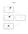
- FIG. 8 is a diagram illustrating an example of a moving body area and a prediction area according to the first embodiment.
- a is a diagram illustrating an example of a moving body area 571 detected in a specific input frame F 1
- b is a diagram illustrating an example of a moving body area 572 detected in a next frame F 2 following the input frame F 1
- c is a diagram illustrating an example of a motion vector 581 obtained from the moving body areas 571 and 572
- d is a diagram illustrating an example of a moving body prediction area 573 , which has been predicted based on the moving body area 572 and the motion vector 581 , in a next input frame F 3 following the input frame F 2 .
- the image capture apparatus 100 can obtain the motion vector 581 indicating the prediction area from the moving body areas 571 and 572 in the input frames F 1 and F 2 . Also, a prediction area 573 in the next input frame F 3 following the input frame F 2 is obtained based on the moving body area 572 and the motion vector 581 . The prediction area 573 is assumed to overlap with the processing area 530 as illustrated in d in the drawing. In such a case, the image capture apparatus 100 acquires a luminance distribution by masking the overlapping part and obtains the amount of exposure from the luminance distribution.
- the motion vector may be obtained from three or more frames, namely the input frames and the background frames. If three or more input frames are used, a vector with an average direction and an average size of those of a plurality of vectors detected in two consecutive input frames in a chronological order is detected as a final motion vector.
- FIG. 9 is a diagram illustrating an example of mask data according to the first embodiment. If the prediction area 573 overlaps with the processing area 530 , the control information generation unit 170 generates mask data for masking the overlapping part as illustrated in the drawing. In the drawing, the blacked out part represents the masked part. The control information generation unit 170 partially masks the processing area 530 based on the mask data and generates control information such as the amount of exposure.
- FIG. 10 is an explanatory diagram of exposure control according to the first embodiment.
- a is an example of the input frame 551 .
- b is an example of a next input frame 552 following the input frame 551 .
- c is an example of the moving body area 572 and the motion vector 581 detected from the input frames 551 and 552 .
- d is an example of a next input frame 553 following the input frame 552 .
- the search light of the vehicle that does not appear in the background frame appears in the input frame 551 , and the search light does not overlap with the processing area 520 .
- the search light also appears in the input frame 552 , and the search light has approached the processing area 520 in comparison to that in the input frame 551 though the search light does not overlap with the processing area 520 .
- the image capture apparatus 100 detects a search light area as the moving body area 572 from the input frames 551 and 552 and detects the motion vector 581 thereof. Then, the image capture apparatus 100 predicts an area corresponding to the moving body in the next frame 553 based on the moving body area 572 and the motion vector 581 and obtains the prediction area 573 .
- the prediction area 573 is assumed to overlap with the processing area 520 . In such a case, the image capture apparatus 100 generates a luminance distribution by masking the overlapping part in the processing area 520 and generates control information including the amount of exposure from the luminance distribution.
- the image capture apparatus 100 controls the aperture value and the exposure time based on the amount of exposure and captures a next input frame 554 .
- d is an example of the input frame 554 . Since the image capture apparatus 100 obtains the amount of exposure by masking the search light part with a high luminance value and performs the exposure control on the input frame 553 , the amount of exposure at the part other than the moving body (such as a search light) in the next input frame 554 becomes a suitable value. As a result, it is possible to prevent image quality from being degraded due to insufficient exposure of the part other than the moving body.
- FIG. 11 is a diagram illustrating an example of an input frame according to the first embodiment.
- a is an enlarged diagram of the input frame 554 illustrated in d in FIG. 10 .
- the image capture apparatus 100 obtains the amount of exposure by masking the moving body (search light) part with the high luminance value in the previous input frame 553 and captures the input frame 554 by controlling exposure based on the amount of exposure. Therefore, insufficient exposure does not occur for the background other than the search light part in the input frame 554 , and image quality is improved.
- b is an example of an input frame according to a comparative example that is captured under exposure control without masking the moving body part with the high luminance value. If the exposure control is performed without masking the moving body part with the high luminance value, a larger amount of exposure than that when no mask is used is generated, and the aperture value and the like are controlled based on the large amount of exposure. As a result, insufficient exposure occurs in the background part with relatively low luminance, and image quality is degraded.
- FIG. 12 is a flowchart illustrating an example of behavior of the image capture apparatus 100 according to the first embodiment.
- the behavior start when an operation for capturing a moving image is performed, for example.
- the image capture apparatus 100 captures an input frame (Step S 901 ).
- the image capture apparatus 100 extracts an extraction area in the input frame, generates an extracted image, and outputs the extracted image to the display apparatus 300 (Step S 902 ).
- the image capture apparatus 100 compares the input frame and a background frame and detects a moving body area (Step S 903 ).
- the image capture apparatus 100 determines whether or not the input frame is a second frame or any of the following frames (Step S 904 ). If the input frame is the second frame or any of the following frames (Step S 904 : Yes), the image capture apparatus 100 predicts an area corresponding to a moving body in the next input frame as a prediction area (Step S 905 ).
- the image capture apparatus 100 determines whether or not the input frame is a third frame or any of the following frames (Step S 906 ).
- Step S 906 If the frame is the third frame or any of the following frames (Step S 906 : Yes), the image capture apparatus 100 masks the prediction area, which has been predicted in the previous frame, in the processing area and generates control information including the amount of exposure (Step S 907 ). However, if the processing area and the prediction area do not overlap with each other, the image capture apparatus 100 generates the control information without masking any part.
- Step S 908 the image capture apparatus 100 generates the control information including the amount of exposure.
- Step S 907 or S 908 the image capture apparatus 100 controls the aperture value and the exposure time based on the amount of exposure (Step S 909 ) and returns to Step S 901 .
- the image capture apparatus 100 can generate appropriate control information even if the moving body overlaps with the processing area since the image capture apparatus 100 predicts the area corresponding to the moving body and generates the control information by excluding the prediction area from the processing area as described above. In this manner, it is possible to improve image quality of the part other than the moving body.
- the image capture apparatus 100 captures the frames under exposure control in the first embodiment
- the frames may be captured under focus control instead of the exposure control.
- the image capture apparatus 100 according to the first modification example is different from that of the first embodiment in that the frames are captured under focus control.
- the control information generation unit 170 generates control information including distance information indicating a distance to an object from the statistical information. For example, a contrast or the like is generated as the distance information.
- the controller 180 controls the position of the focus lens in the image capture lens 11 based on the distance information.
- the position of the focus lens is controlled so as to be a position with the highest contrast.
- FIG. 13 is a flowchart illustrating an example of behavior of the image capture apparatus 100 according to the first modification example of the first embodiment.
- the behavior of the image capture apparatus 100 according to the first modification example is different from that of the first embodiment in that Steps S 911 to S 913 are executed instead of Steps S 907 to S 909 .
- Step S 906 If the input frame is the third frame or any of the following input frames (Step S 906 : Yes), the image capture apparatus 100 generates control information including the contrast by masking the prediction area (Step S 911 ). If the input frame is not the second frame or any of the following frames (Step S 904 : No) or if the input frame is not the third frame or any of the following frames (Step S 906 : No), the image capture apparatus 100 generates the control information including the contrast (Step S 912 ).
- Step S 911 or S 912 the image capture apparatus 100 controls the position of the focus lens based on the contrast (Step S 913 ) and returns to Step S 901 .
- the image capture apparatus 100 may perform both the exposure control and the focus control.
- FIG. 14 is a diagram illustrating an example of an input frame 591 according to the first embodiment.
- the image capture apparatus 100 obtains a contrast by masking a part corresponding to a moving body 592 at a significantly different distance from that of the background in the frame before the input frame 591 , and captures the input frame 591 under focus control based on the contrast. Therefore, the input frame 591 in focus on the background other than the part corresponding to the moving body 592 is obtained.
- b is an example of a frame according to a comparative example that is captured under focus control without masking the part corresponding to the moving body at a significantly different distance.
- a contrast different from that in the case of not masking the part is generated, and the position of the focus lens is controlled based on the contrast.
- the background part at a different distance is not focused, and image quality is degraded.
- the image capture apparatus 100 can generate an appropriate contrast even if the moving body overlaps with the processing area since the image capture apparatus 100 predicts the moving body area and generates the contrast while excluding the prediction area from the processing area as described above. In this manner, the image capture apparatus 100 can extract an image in focus on the part other than the moving body.
- the image capture apparatus 100 captures frames under exposure control in the first embodiment
- the frames may be captured under white balance control instead of exposure control.
- the image capture apparatus 100 according to the first modification example is different from that of the first embodiment in that the frames are captured under white balance control.
- the statistical information generation unit 160 generates a luminance distribution for each color.
- the control information generation unit 170 according to the second modification example generates control information including statistical amounts (a sum and an average) of pixel values for each color as color component amounts from the statistical information.
- the controller 180 transmits a control signal to the signal processing unit 113 and causes the signal processing unit 113 to change a gain for each color such that a ratio of the respective color component amounts becomes a set value. For example, an R gain for red pixel data, a B gain for blue pixel data, and the like are controlled.
- the signal processing unit 113 amplifies the pixel data using the gains controlled by the controller 180 .
- FIG. 15 is a flowchart illustrating an example of behavior of the image capture apparatus 100 according to the second modification example of the first embodiment.
- the behavior of the image capture apparatus 100 according to the second modification example is different from that of the first embodiment in that Steps S 921 to S 923 are executed instead of Steps S 907 to S 909 .
- Step S 906 If the input frame is the third frame or any of the following frames (Step S 906 : Yes), the image capture apparatus 100 generates control information including the color component amounts by masking the prediction area (Step S 921 ). If the input frame is not the second frame or any of the following frames (Step S 904 : No) or if the input frame is not the third frame or any of the following frames (Step S 906 : No), the image capture apparatus 100 generates the control information including the color component amounts (Step S 922 ).
- Step S 921 or S 922 the image capture apparatus 100 controls the R gain and the B gain based on the color component amounts (Step S 923 ) and returns to Step S 901 .
- the image capture apparatus 100 may perform two or more of the exposure control, the focus control, and the white balance control.
- the image capture apparatus 100 can control the white balance of the part other than the moving body such that it has an appropriate value since the image capture apparatus 100 predicts the area corresponding to the moving body and generates the color component amounts while excluding the prediction area from the processing area.
- the statistical information generation unit 160 performs the statistical processing by excluding (that is, masking) the part that overlaps with the prediction area in the first embodiment
- the statistical processing may be that performed on the part that overlaps the prediction area instead of the statistical processing excluding (that is, masking) the part that overlaps with the prediction area.
- the statistical information generation unit 160 according to the third modification example is different from that of the first embodiment in that the statistical information generation unit 160 performs the statistical processing only on the part that overlaps with the prediction area.
- the behavior of the image capture apparatus 100 according to the third modification example is different from that of the first embodiment in that the part other than the prediction area is masked instead of masking the prediction area in Step S 907 .
- the image capture apparatus 100 may perform two or more of the exposure control, the focus control, and the white balance control.
- the image capture apparatus 100 can control the control information including the amount of exposure of the moving body part such that it has an appropriate value since the image capture apparatus 100 predicts the area corresponding to the moving body and generates the control information including the amount of exposure only for the area, which overlaps with the prediction area, in the processing area as a target.
- the image capture apparatus 100 performs the exposure control and extracts and outputs the extracted image every time a frame is captured in the first embodiment.
- the image capture apparatus 100 sets a frame rate at which the extracted image is output to be the same as a frame rate of the exposure control.
- the frame rate at which the extracted image is output is smaller than the frame rate of the exposure control.
- a configuration may be conceived in which both the exposure control and the output of the extracted image are performed for even frames while only the exposure control is performed for odd frames. In such a case, there is no influence on the image quality of the extracted image since no extracted image is output from a frame F 3 even if the amount of exposure changes from an even frame F 2 to the next odd frame F 3 .
- the image capture apparatus 100 can image the frame F 4 with a suitable amount of exposure and output the extracted image with high image quality.
- the image capture apparatus 100 according to the second embodiment is different from that of the first embodiment in that the extracted image is extracted every time the plurality of frames are captured.
- FIG. 16 is a flowchart illustrating behavior of the image capture apparatus 100 according to the second embodiment.
- the image capture apparatus 100 captures an input frame (Step S 901 ) and determines whether or not the input frame is an odd frame of an odd number (Step S 931 ). If the input frame is an odd frame (Step S 931 : Yes), the image capture apparatus 100 performs parameter control processing (Step S 940 ). In contrast, if the input frame is an even frame (Step S 931 : No), the image capture apparatus 100 performs display output processing (Step S 950 ). After Step S 940 or S 950 , the image capture apparatus 100 returns to Step S 901 .
- FIG. 17 is a flowchart illustrating an example of parameter control processing according to the second embodiment.
- the image capture apparatus 100 detects a moving body area (Step S 941 ) and determines whether or not the input frame is a third frame or any of the following frames (Step S 942 ). If the input frame is the third frame or any of the following frames (Step S 942 : Yes), an area corresponding to the moving body in the next frame is predicted as a prediction area (Step S 943 ). Then, the image capture apparatus 100 generates control information including the amount of exposure by masking the prediction area in the processing area (Step S 944 ).
- Step S 942 the image capture apparatus 100 generates the control information including the amount of exposure (Step S 945 ).
- Step S 944 or S 945 the image capture apparatus 100 controls the aperture value and the exposure time based on the amount of exposure (Step S 946 ) and completes the parameter control processing.
- FIG. 18 is a flowchart illustrating an example of display output processing according to the second embodiment.
- the image capture apparatus 100 extracts an extraction area from a frame, generates an extracted image, and outputs the extracted image to the display apparatus 300 (Step S 951 ).
- the image capture apparatus 100 detects a moving body area (Step S 952 ) and predicts an area corresponding to a moving body in the next frame as a prediction area (Step S 953 ).
- the image capture apparatus 100 determines whether or not the input frame is a fourth frame or any of the following frames (Step S 954 ). If the input frame is the fourth frame or any of the following frames (Step S 954 : Yes), the image capture apparatus 100 generates control information including the amount of exposure by masking the prediction area in the processing area (Step S 955 ).
- Step S 954 the image capture apparatus 100 generates the control information including the amount of exposure (Step S 956 ).
- Step S 955 or S 956 the image capture apparatus 100 controls the aperture value and the exposure time based on the amount of exposure (Step S 957 ) and completes the display output control processing.
- the image capture apparatus 100 generates the extracted image every time two input frames are captured, the extracted image may be generated every time three or more input frames are captured.
- the image capture apparatus 100 can maintain image quality of the extracted image even if the amount of exposure rapidly changes since the image capture apparatus 100 extracts the extracted image every time a plurality of input frames are captured as described above.
- the processing sequences that are described in the embodiments described above may be handled as a method having a series of sequences or may be handled as a program for causing a computer to execute the series of sequences and recording medium storing the program.
- a recording medium a hard disk, a CD (Compact Disc), an MD (MiniDisc), and a DVD (Digital Versatile Disk), a memory card, and a Blu-ray disc (registered trademark) can be used.
- present technology may also be configured as below.
- An image capture control apparatus including:
- a moving body detection unit that detects, as a moving body area, an area of a moving body from an input frame every time the input frame captured by an image capture unit is input;
- a prediction unit that predicts, as a prediction area, an area corresponding to the moving body area in a next input frame following the input frame from the moving body area every time the input frame is input;
- a statistical information generation unit that generates statistical information by performing predetermined statistical processing on each of pixel values of pixels in either an area excluding the predicted prediction area from a specific processing area in the input frame or an area that overlaps the prediction area in the processing area every time the input frame is input;
- control information generation unit that generates predetermined control information for controlling the image capture unit based on the statistical information every time the statistical information is generated
- controller that controls the image capture unit and causes the image capture unit to capture the next input frame based on the control information every time the control information is generated.
- the image capture control apparatus further including:
- an image extraction unit that extracts an extraction area including at least a part of the processing area in the input frame.
- the image extraction unit extracts the extraction area every time the input frame is input a plurality of times.
- the extraction area includes the entire processing area.
- processing area includes the entire extraction area.
- An image capture apparatus including:
- an image capture unit that images an input frame a plurality of times
- a prediction unit that predicts, as a prediction area, an area corresponding to the moving body area in a next input frame following the input frame from the moving body area every time the input frame is input;
- a statistical information generation unit that generates statistical information by performing predetermined statistical processing on each of pixel values of pixels in either an image excluding the predicted prediction area from a specific processing area in the input frame or an area that overlaps the prediction area in the processing area every time the input frame is input;
- a statistical information generation unit that generates statistical information by performing predetermined statistical processing on each of pixel values of pixels in an area excluding a prediction area predicted in an input frame before the input frame from the specific processing area in the input frame every time the input frame is input;
- control information generation unit that generates predetermined control information for controlling the image capture unit based on the statistical information every time the statistical information is generated
- controller that controls the image capture unit and causes the image capture unit to capture the next input frame based on the control information every time the control information is generated.
- the image capture unit performs exposure with light intensity adjusted in accordance with an aperture value during an exposure time
- control information includes an amount of exposure
- the controller controls at least one of the aperture value and the exposure time based on the amount of exposure.
- the image capture unit includes a focus lens
- control information includes distance information regarding a distance to an object
- the controller controls a position of the focus lens based on the distance information.
- the image capture unit includes
- control information includes statistical amounts of pixel values of the pixel data for each color
- the controller controls the gain for each color based on the statistical amounts.
- a method of controlling an image capture control apparatus including:
- a moving body detection procedure in which a moving body detection unit detects, as a moving body area, an area of a moving body from an input frame every time the input frame captured by an image capture unit is input;
- a prediction unit predicts, as a prediction area, an area corresponding to the moving body area in a next input frame following the input frame from the moving body area every time the input frame is input;
- a statistical information generation procedure in which a statistical information generation unit generates statistical information by performing predetermined statistical processing on each of pixel values of pixels in either an area excluding the predicted prediction area from a specific processing area in the input frame or an area that overlaps the prediction area in the processing area every time the input frame is input;
- control information generation procedure in which a control information generation unit generates predetermined control information for controlling the image capture unit based on the statistical information every time the statistical information is generated;
- a control procedure in which a controller controls the image capture unit and causes the image capture unit to capture the next input frame based on the control information every time the control information is generated.
Landscapes
- Engineering & Computer Science (AREA)
- Multimedia (AREA)
- Physics & Mathematics (AREA)
- Signal Processing (AREA)
- General Physics & Mathematics (AREA)
- Theoretical Computer Science (AREA)
- Optics & Photonics (AREA)
- General Engineering & Computer Science (AREA)
- Studio Devices (AREA)
- Exposure Control For Cameras (AREA)
- Focusing (AREA)
- Automatic Focus Adjustment (AREA)
Abstract
Description
- 1. First embodiment (Example in which amount of exposure is obtained by masking prediction area)
- 2. Second embodiment (Example in which amount of exposure is obtained by masking prediction area and generating an extracted image for each of plurality of frames)
-
- an image sensor that generates a plurality of pieces of pixel data with mutually different colors, and
- a signal processing unit that amplifies the pixel data using a predetermined gain,
- 100 image capture apparatus
- 110 image capture unit
- 111 image capture lens
- 112 diaphragm blade
- 113 signal processing unit
- 120 image extraction unit
- 130 image quality adjustment unit
- 140 moving body detection unit
- 141 background storage unit
- 142 difference area detection unit
- 150 prediction unit
- 160 statistical information generation unit
- 170 control information generation unit
- 180 controller
- 200 image sensor
- 210 row scanning circuit
- 220 pixel array unit
- 230 pixel circuit
- 231 photodiode
- 232 transfer transistor
- 233 reset transistor
- 234 floating diffusion layer
- 235 amplification transistor
- 236 selection transistor
- 250 timing control circuit
- 260 AD conversion unit
- 270 column scanning circuit
- 300 display apparatus
Claims (10)
Applications Claiming Priority (3)
| Application Number | Priority Date | Filing Date | Title |
|---|---|---|---|
| JP2014-174735 | 2014-08-29 | ||
| JP2014174735 | 2014-08-29 | ||
| PCT/JP2015/069744 WO2016031403A1 (en) | 2014-08-29 | 2015-07-09 | Image capture control device, image capture device, and method for controlling image capture device |
Publications (2)
| Publication Number | Publication Date |
|---|---|
| US20170272637A1 US20170272637A1 (en) | 2017-09-21 |
| US10270980B2 true US10270980B2 (en) | 2019-04-23 |
Family
ID=55399306
Family Applications (1)
| Application Number | Title | Priority Date | Filing Date |
|---|---|---|---|
| US15/505,312 Active 2035-07-24 US10270980B2 (en) | 2014-08-29 | 2015-07-09 | Image capture control apparatus, image capture apparatus, and method of controlling image capture apparatus |
Country Status (3)
| Country | Link |
|---|---|
| US (1) | US10270980B2 (en) |
| JP (1) | JP6666841B2 (en) |
| WO (1) | WO2016031403A1 (en) |
Families Citing this family (7)
| Publication number | Priority date | Publication date | Assignee | Title |
|---|---|---|---|---|
| KR102076531B1 (en) * | 2015-10-27 | 2020-02-12 | 한국전자통신연구원 | System and method for tracking position based on multi sensor |
| JP6851854B2 (en) * | 2017-02-22 | 2021-03-31 | キヤノン株式会社 | Control method of image processing device, imaging device and image processing device |
| JP2018198406A (en) * | 2017-05-24 | 2018-12-13 | ルネサスエレクトロニクス株式会社 | Surveillance camera system and image processing apparatus |
| EP3661188B1 (en) * | 2018-11-27 | 2020-10-28 | Axis AB | A method for reducing intensity variations in a video image stream depicting a scene |
| JP7281897B2 (en) * | 2018-12-12 | 2023-05-26 | キヤノン株式会社 | IMAGING DEVICE, CONTROL METHOD AND PROGRAM THEREOF |
| JP7570912B2 (en) * | 2020-12-14 | 2024-10-22 | キヤノン株式会社 | Imaging device, imaging method, and program |
| JP7725226B2 (en) * | 2021-04-28 | 2025-08-19 | キヤノン株式会社 | Electronic device, electronic device control method, and recording medium |
Citations (8)
| Publication number | Priority date | Publication date | Assignee | Title |
|---|---|---|---|---|
| JPH10164420A (en) | 1996-11-26 | 1998-06-19 | Canon Inc | Camera control system and device |
| JP2005109705A (en) | 2003-09-29 | 2005-04-21 | Mitsubishi Electric Corp | Imaging processing device |
| US20050259177A1 (en) | 2004-05-18 | 2005-11-24 | Canon Kabushiki Kaisha | Imaging apparatus |
| JP2006243373A (en) | 2005-03-03 | 2006-09-14 | Matsushita Electric Ind Co Ltd | Video signal processing apparatus, imaging apparatus equipped with the video signal processing apparatus, video signal processing method, and video signal processing program |
| JP2008107565A (en) | 2006-10-25 | 2008-05-08 | Canon Inc | Imaging apparatus and exposure control method for imaging apparatus |
| JP2008141239A (en) | 2006-11-29 | 2008-06-19 | Canon Inc | IMAGING DEVICE, ITS CONTROL METHOD, PROGRAM, AND STORAGE MEDIUM |
| WO2013088917A1 (en) | 2011-12-13 | 2013-06-20 | ソニー株式会社 | Image processing device, image processing method, and recording medium |
| US9420166B2 (en) * | 2012-02-13 | 2016-08-16 | Nokia Technologies Oy | Method and apparatus for enhanced automatic adjustment of focus, exposure and white balance in digital photography |
-
2015
- 2015-07-09 US US15/505,312 patent/US10270980B2/en active Active
- 2015-07-09 JP JP2016545036A patent/JP6666841B2/en active Active
- 2015-07-09 WO PCT/JP2015/069744 patent/WO2016031403A1/en not_active Ceased
Patent Citations (10)
| Publication number | Priority date | Publication date | Assignee | Title |
|---|---|---|---|---|
| JPH10164420A (en) | 1996-11-26 | 1998-06-19 | Canon Inc | Camera control system and device |
| JP2005109705A (en) | 2003-09-29 | 2005-04-21 | Mitsubishi Electric Corp | Imaging processing device |
| US20050259177A1 (en) | 2004-05-18 | 2005-11-24 | Canon Kabushiki Kaisha | Imaging apparatus |
| JP2005331590A (en) | 2004-05-18 | 2005-12-02 | Canon Inc | Imaging unit |
| JP2006243373A (en) | 2005-03-03 | 2006-09-14 | Matsushita Electric Ind Co Ltd | Video signal processing apparatus, imaging apparatus equipped with the video signal processing apparatus, video signal processing method, and video signal processing program |
| JP2008107565A (en) | 2006-10-25 | 2008-05-08 | Canon Inc | Imaging apparatus and exposure control method for imaging apparatus |
| JP2008141239A (en) | 2006-11-29 | 2008-06-19 | Canon Inc | IMAGING DEVICE, ITS CONTROL METHOD, PROGRAM, AND STORAGE MEDIUM |
| WO2013088917A1 (en) | 2011-12-13 | 2013-06-20 | ソニー株式会社 | Image processing device, image processing method, and recording medium |
| US20140334683A1 (en) | 2011-12-13 | 2014-11-13 | Sony Corporation | Image processing apparatus, image processing method, and recording medium |
| US9420166B2 (en) * | 2012-02-13 | 2016-08-16 | Nokia Technologies Oy | Method and apparatus for enhanced automatic adjustment of focus, exposure and white balance in digital photography |
Also Published As
| Publication number | Publication date |
|---|---|
| JP6666841B2 (en) | 2020-03-18 |
| WO2016031403A1 (en) | 2016-03-03 |
| US20170272637A1 (en) | 2017-09-21 |
| JPWO2016031403A1 (en) | 2017-06-08 |
Similar Documents
| Publication | Publication Date | Title |
|---|---|---|
| US10270980B2 (en) | Image capture control apparatus, image capture apparatus, and method of controlling image capture apparatus | |
| US9571742B2 (en) | Image capture apparatus and control method thereof | |
| CN103733607A (en) | Device and method for detecting moving objects | |
| KR20140041206A (en) | Camera and camera controlling method for generating privacy mask | |
| US20240259686A1 (en) | Imaging apparatus | |
| US11171164B2 (en) | Image sensor, image processing method, and electronic device | |
| US9648222B2 (en) | Image capturing apparatus that controls supply of amperage when reading out pixel signals and method for controlling the same | |
| US20170098136A1 (en) | Image processing apparatus, method of controlling the same, and storage medium | |
| US8699750B2 (en) | Image processing apparatus | |
| US10863078B2 (en) | Focus detection apparatus and method | |
| US10116865B2 (en) | Image processing apparatus and image processing method for calculating motion vector between images with different in-focus positions | |
| US20130076940A1 (en) | Photographing apparatus and method of detecting distortion thereof | |
| JP6172973B2 (en) | Image processing device | |
| WO2020071104A1 (en) | Solid-state imaging device, drive method, and electronic apparatus | |
| US20140341483A1 (en) | Image processing apparatus and image processing method | |
| US20120307130A1 (en) | Digital photographing apparatus, auto-focusing method, and computer-readable storage medium for executing the auto-focusing method | |
| US20100182460A1 (en) | Image processing apparatus | |
| US10237469B2 (en) | Information processing apparatus, information processing method, and storage medium | |
| US10205870B2 (en) | Image capturing apparatus and control method thereof | |
| US11563904B2 (en) | Imaging apparatus and imaging control method | |
| US20150085172A1 (en) | Image capturing apparatus and control method thereof | |
| JP5395503B2 (en) | Display control apparatus and operation control method thereof | |
| JP4871664B2 (en) | IMAGING DEVICE AND IMAGING DEVICE CONTROL METHOD | |
| JP7571173B2 (en) | Image capture device, image capture device control method, and program | |
| JP6421032B2 (en) | Focus detection apparatus, focus detection method, and focus detection program |
Legal Events
| Date | Code | Title | Description |
|---|---|---|---|
| AS | Assignment |
Owner name: SONY CORPORATION, JAPAN Free format text: ASSIGNMENT OF ASSIGNORS INTEREST;ASSIGNOR:KAWAZOE, DAISUKE;REEL/FRAME:042368/0965 Effective date: 20161129 |
|
| AS | Assignment |
Owner name: SONY SEMICONDUCTOR SOLUTIONS CORPORATION, JAPAN Free format text: CORRECTIVE ASSIGNMENT TO CORRECT THE ASSIGNEE NAME AND STREET ADDRESS PREVIOUSLY RECORDED AT REEL: 042368 FRAME: 0965. ASSIGNOR(S) HEREBY CONFIRMS THE ASSIGNMENT;ASSIGNOR:KAWAZOE, DAISUKE;REEL/FRAME:042776/0384 Effective date: 20161129 |
|
| STPP | Information on status: patent application and granting procedure in general |
Free format text: PUBLICATIONS -- ISSUE FEE PAYMENT VERIFIED |
|
| STCF | Information on status: patent grant |
Free format text: PATENTED CASE |
|
| MAFP | Maintenance fee payment |
Free format text: PAYMENT OF MAINTENANCE FEE, 4TH YEAR, LARGE ENTITY (ORIGINAL EVENT CODE: M1551); ENTITY STATUS OF PATENT OWNER: LARGE ENTITY Year of fee payment: 4 |