US10265083B2 - Systems and methods for preparing bone voids to receive a prosthesis - Google Patents
Systems and methods for preparing bone voids to receive a prosthesis Download PDFInfo
- Publication number
- US10265083B2 US10265083B2 US15/597,851 US201715597851A US10265083B2 US 10265083 B2 US10265083 B2 US 10265083B2 US 201715597851 A US201715597851 A US 201715597851A US 10265083 B2 US10265083 B2 US 10265083B2
- Authority
- US
- United States
- Prior art keywords
- bone
- broach
- offset
- reamer
- void
- Prior art date
- Legal status (The legal status is an assumption and is not a legal conclusion. Google has not performed a legal analysis and makes no representation as to the accuracy of the status listed.)
- Active
Links
- 210000000988 bone and bone Anatomy 0.000 title claims abstract description 197
- 238000000034 method Methods 0.000 title claims abstract description 55
- 239000011800 void material Substances 0.000 claims abstract description 82
- 239000000945 filler Substances 0.000 claims abstract description 21
- 210000003127 knee Anatomy 0.000 claims abstract description 8
- 238000005520 cutting process Methods 0.000 claims description 47
- 239000000853 adhesive Substances 0.000 claims description 12
- 230000001070 adhesive effect Effects 0.000 claims description 12
- 210000000629 knee joint Anatomy 0.000 claims 10
- 238000011882 arthroplasty Methods 0.000 claims 1
- 239000007943 implant Substances 0.000 abstract description 15
- 238000004513 sizing Methods 0.000 description 15
- 238000002513 implantation Methods 0.000 description 10
- RTAQQCXQSZGOHL-UHFFFAOYSA-N Titanium Chemical compound [Ti] RTAQQCXQSZGOHL-UHFFFAOYSA-N 0.000 description 9
- 230000000295 complement effect Effects 0.000 description 9
- 239000010936 titanium Substances 0.000 description 9
- 238000002360 preparation method Methods 0.000 description 8
- 229910052719 titanium Inorganic materials 0.000 description 8
- 230000008468 bone growth Effects 0.000 description 5
- 238000000605 extraction Methods 0.000 description 5
- 210000002303 tibia Anatomy 0.000 description 5
- 239000000560 biocompatible material Substances 0.000 description 4
- 230000007246 mechanism Effects 0.000 description 4
- 238000001356 surgical procedure Methods 0.000 description 4
- 210000000689 upper leg Anatomy 0.000 description 4
- 206010070918 Bone deformity Diseases 0.000 description 3
- 230000008901 benefit Effects 0.000 description 3
- 239000002639 bone cement Substances 0.000 description 3
- 230000013011 mating Effects 0.000 description 3
- 239000007787 solid Substances 0.000 description 3
- 241000283984 Rodentia Species 0.000 description 2
- 230000007423 decrease Effects 0.000 description 2
- 230000007547 defect Effects 0.000 description 2
- 238000009826 distribution Methods 0.000 description 2
- 238000005553 drilling Methods 0.000 description 2
- 210000001624 hip Anatomy 0.000 description 2
- 238000013150 knee replacement Methods 0.000 description 2
- 239000000463 material Substances 0.000 description 2
- 206010065687 Bone loss Diseases 0.000 description 1
- 206010010356 Congenital anomaly Diseases 0.000 description 1
- 229910001200 Ferrotitanium Inorganic materials 0.000 description 1
- 210000003423 ankle Anatomy 0.000 description 1
- 206010003246 arthritis Diseases 0.000 description 1
- 230000003190 augmentative effect Effects 0.000 description 1
- 230000005540 biological transmission Effects 0.000 description 1
- 230000010072 bone remodeling Effects 0.000 description 1
- 230000008859 change Effects 0.000 description 1
- 238000004891 communication Methods 0.000 description 1
- 230000007850 degeneration Effects 0.000 description 1
- 238000003780 insertion Methods 0.000 description 1
- 230000037431 insertion Effects 0.000 description 1
- 230000001788 irregular Effects 0.000 description 1
- 238000002955 isolation Methods 0.000 description 1
- 238000003754 machining Methods 0.000 description 1
- 229910052751 metal Inorganic materials 0.000 description 1
- 239000002184 metal Substances 0.000 description 1
- 238000003801 milling Methods 0.000 description 1
- 238000012986 modification Methods 0.000 description 1
- 230000004048 modification Effects 0.000 description 1
- 230000000399 orthopedic effect Effects 0.000 description 1
- 229920000642 polymer Polymers 0.000 description 1
- 230000008569 process Effects 0.000 description 1
- 238000011084 recovery Methods 0.000 description 1
- 210000002832 shoulder Anatomy 0.000 description 1
- 230000000087 stabilizing effect Effects 0.000 description 1
- 229910001220 stainless steel Inorganic materials 0.000 description 1
- 239000010935 stainless steel Substances 0.000 description 1
- 238000012546 transfer Methods 0.000 description 1
- 210000000707 wrist Anatomy 0.000 description 1
Images


Classifications
-
- A—HUMAN NECESSITIES
- A61—MEDICAL OR VETERINARY SCIENCE; HYGIENE
- A61B—DIAGNOSIS; SURGERY; IDENTIFICATION
- A61B17/00—Surgical instruments, devices or methods
- A61B17/16—Instruments for performing osteoclasis; Drills or chisels for bones; Trepans
- A61B17/1662—Instruments for performing osteoclasis; Drills or chisels for bones; Trepans for particular parts of the body
-
- A—HUMAN NECESSITIES
- A61—MEDICAL OR VETERINARY SCIENCE; HYGIENE
- A61B—DIAGNOSIS; SURGERY; IDENTIFICATION
- A61B17/00—Surgical instruments, devices or methods
- A61B17/16—Instruments for performing osteoclasis; Drills or chisels for bones; Trepans
- A61B17/164—Instruments for performing osteoclasis; Drills or chisels for bones; Trepans intramedullary
-
- A—HUMAN NECESSITIES
- A61—MEDICAL OR VETERINARY SCIENCE; HYGIENE
- A61B—DIAGNOSIS; SURGERY; IDENTIFICATION
- A61B17/00—Surgical instruments, devices or methods
- A61B17/16—Instruments for performing osteoclasis; Drills or chisels for bones; Trepans
- A61B17/1662—Instruments for performing osteoclasis; Drills or chisels for bones; Trepans for particular parts of the body
- A61B17/1664—Instruments for performing osteoclasis; Drills or chisels for bones; Trepans for particular parts of the body for the hip
- A61B17/1668—Instruments for performing osteoclasis; Drills or chisels for bones; Trepans for particular parts of the body for the hip for the upper femur
-
- A—HUMAN NECESSITIES
- A61—MEDICAL OR VETERINARY SCIENCE; HYGIENE
- A61B—DIAGNOSIS; SURGERY; IDENTIFICATION
- A61B17/00—Surgical instruments, devices or methods
- A61B17/16—Instruments for performing osteoclasis; Drills or chisels for bones; Trepans
- A61B17/1662—Instruments for performing osteoclasis; Drills or chisels for bones; Trepans for particular parts of the body
- A61B17/1675—Instruments for performing osteoclasis; Drills or chisels for bones; Trepans for particular parts of the body for the knee
-
- A—HUMAN NECESSITIES
- A61—MEDICAL OR VETERINARY SCIENCE; HYGIENE
- A61B—DIAGNOSIS; SURGERY; IDENTIFICATION
- A61B17/00—Surgical instruments, devices or methods
- A61B17/16—Instruments for performing osteoclasis; Drills or chisels for bones; Trepans
- A61B17/17—Guides or aligning means for drills, mills, pins or wires
- A61B17/1717—Guides or aligning means for drills, mills, pins or wires for applying intramedullary nails or pins
-
- A—HUMAN NECESSITIES
- A61—MEDICAL OR VETERINARY SCIENCE; HYGIENE
- A61B—DIAGNOSIS; SURGERY; IDENTIFICATION
- A61B17/00—Surgical instruments, devices or methods
- A61B17/16—Instruments for performing osteoclasis; Drills or chisels for bones; Trepans
- A61B17/17—Guides or aligning means for drills, mills, pins or wires
- A61B17/1739—Guides or aligning means for drills, mills, pins or wires specially adapted for particular parts of the body
- A61B17/1742—Guides or aligning means for drills, mills, pins or wires specially adapted for particular parts of the body for the hip
- A61B17/175—Guides or aligning means for drills, mills, pins or wires specially adapted for particular parts of the body for the hip for preparing the femur for hip prosthesis insertion
-
- A—HUMAN NECESSITIES
- A61—MEDICAL OR VETERINARY SCIENCE; HYGIENE
- A61B—DIAGNOSIS; SURGERY; IDENTIFICATION
- A61B17/00—Surgical instruments, devices or methods
- A61B17/16—Instruments for performing osteoclasis; Drills or chisels for bones; Trepans
- A61B17/17—Guides or aligning means for drills, mills, pins or wires
- A61B17/1739—Guides or aligning means for drills, mills, pins or wires specially adapted for particular parts of the body
- A61B17/1764—Guides or aligning means for drills, mills, pins or wires specially adapted for particular parts of the body for the knee
-
- A—HUMAN NECESSITIES
- A61—MEDICAL OR VETERINARY SCIENCE; HYGIENE
- A61F—FILTERS IMPLANTABLE INTO BLOOD VESSELS; PROSTHESES; DEVICES PROVIDING PATENCY TO, OR PREVENTING COLLAPSING OF, TUBULAR STRUCTURES OF THE BODY, e.g. STENTS; ORTHOPAEDIC, NURSING OR CONTRACEPTIVE DEVICES; FOMENTATION; TREATMENT OR PROTECTION OF EYES OR EARS; BANDAGES, DRESSINGS OR ABSORBENT PADS; FIRST-AID KITS
- A61F2/00—Filters implantable into blood vessels; Prostheses, i.e. artificial substitutes or replacements for parts of the body; Appliances for connecting them with the body; Devices providing patency to, or preventing collapsing of, tubular structures of the body, e.g. stents
- A61F2/02—Prostheses implantable into the body
- A61F2/30—Joints
- A61F2/38—Joints for elbows or knees
- A61F2/3859—Femoral components
-
- A—HUMAN NECESSITIES
- A61—MEDICAL OR VETERINARY SCIENCE; HYGIENE
- A61F—FILTERS IMPLANTABLE INTO BLOOD VESSELS; PROSTHESES; DEVICES PROVIDING PATENCY TO, OR PREVENTING COLLAPSING OF, TUBULAR STRUCTURES OF THE BODY, e.g. STENTS; ORTHOPAEDIC, NURSING OR CONTRACEPTIVE DEVICES; FOMENTATION; TREATMENT OR PROTECTION OF EYES OR EARS; BANDAGES, DRESSINGS OR ABSORBENT PADS; FIRST-AID KITS
- A61F2/00—Filters implantable into blood vessels; Prostheses, i.e. artificial substitutes or replacements for parts of the body; Appliances for connecting them with the body; Devices providing patency to, or preventing collapsing of, tubular structures of the body, e.g. stents
- A61F2/02—Prostheses implantable into the body
- A61F2/30—Joints
- A61F2/38—Joints for elbows or knees
- A61F2/389—Tibial components
-
- A—HUMAN NECESSITIES
- A61—MEDICAL OR VETERINARY SCIENCE; HYGIENE
- A61B—DIAGNOSIS; SURGERY; IDENTIFICATION
- A61B17/00—Surgical instruments, devices or methods
- A61B17/16—Instruments for performing osteoclasis; Drills or chisels for bones; Trepans
- A61B17/1613—Component parts
- A61B17/1615—Drill bits, i.e. rotating tools extending from a handpiece to contact the worked material
-
- A—HUMAN NECESSITIES
- A61—MEDICAL OR VETERINARY SCIENCE; HYGIENE
- A61F—FILTERS IMPLANTABLE INTO BLOOD VESSELS; PROSTHESES; DEVICES PROVIDING PATENCY TO, OR PREVENTING COLLAPSING OF, TUBULAR STRUCTURES OF THE BODY, e.g. STENTS; ORTHOPAEDIC, NURSING OR CONTRACEPTIVE DEVICES; FOMENTATION; TREATMENT OR PROTECTION OF EYES OR EARS; BANDAGES, DRESSINGS OR ABSORBENT PADS; FIRST-AID KITS
- A61F2/00—Filters implantable into blood vessels; Prostheses, i.e. artificial substitutes or replacements for parts of the body; Appliances for connecting them with the body; Devices providing patency to, or preventing collapsing of, tubular structures of the body, e.g. stents
- A61F2/02—Prostheses implantable into the body
- A61F2/30—Joints
- A61F2002/30001—Additional features of subject-matter classified in A61F2/28, A61F2/30 and subgroups thereof
- A61F2002/30316—The prosthesis having different structural features at different locations within the same prosthesis; Connections between prosthetic parts; Special structural features of bone or joint prostheses not otherwise provided for
- A61F2002/30535—Special structural features of bone or joint prostheses not otherwise provided for
- A61F2002/30604—Special structural features of bone or joint prostheses not otherwise provided for modular
-
- A—HUMAN NECESSITIES
- A61—MEDICAL OR VETERINARY SCIENCE; HYGIENE
- A61F—FILTERS IMPLANTABLE INTO BLOOD VESSELS; PROSTHESES; DEVICES PROVIDING PATENCY TO, OR PREVENTING COLLAPSING OF, TUBULAR STRUCTURES OF THE BODY, e.g. STENTS; ORTHOPAEDIC, NURSING OR CONTRACEPTIVE DEVICES; FOMENTATION; TREATMENT OR PROTECTION OF EYES OR EARS; BANDAGES, DRESSINGS OR ABSORBENT PADS; FIRST-AID KITS
- A61F2/00—Filters implantable into blood vessels; Prostheses, i.e. artificial substitutes or replacements for parts of the body; Appliances for connecting them with the body; Devices providing patency to, or preventing collapsing of, tubular structures of the body, e.g. stents
- A61F2/02—Prostheses implantable into the body
- A61F2/30—Joints
- A61F2/30721—Accessories
- A61F2/30734—Modular inserts, sleeves or augments, e.g. placed on proximal part of stem for fixation purposes or wedges for bridging a bone defect
- A61F2002/30736—Augments or augmentation pieces, e.g. wedges or blocks for bridging a bone defect
-
- A—HUMAN NECESSITIES
- A61—MEDICAL OR VETERINARY SCIENCE; HYGIENE
- A61F—FILTERS IMPLANTABLE INTO BLOOD VESSELS; PROSTHESES; DEVICES PROVIDING PATENCY TO, OR PREVENTING COLLAPSING OF, TUBULAR STRUCTURES OF THE BODY, e.g. STENTS; ORTHOPAEDIC, NURSING OR CONTRACEPTIVE DEVICES; FOMENTATION; TREATMENT OR PROTECTION OF EYES OR EARS; BANDAGES, DRESSINGS OR ABSORBENT PADS; FIRST-AID KITS
- A61F2/00—Filters implantable into blood vessels; Prostheses, i.e. artificial substitutes or replacements for parts of the body; Appliances for connecting them with the body; Devices providing patency to, or preventing collapsing of, tubular structures of the body, e.g. stents
- A61F2/02—Prostheses implantable into the body
- A61F2/30—Joints
- A61F2/30767—Special external or bone-contacting surface, e.g. coating for improving bone ingrowth
- A61F2/30771—Special external or bone-contacting surface, e.g. coating for improving bone ingrowth applied in original prostheses, e.g. holes or grooves
- A61F2002/30878—Special external or bone-contacting surface, e.g. coating for improving bone ingrowth applied in original prostheses, e.g. holes or grooves with non-sharp protrusions, for instance contacting the bone for anchoring, e.g. keels, pegs, pins, posts, shanks, stems, struts
- A61F2002/30884—Fins or wings, e.g. longitudinal wings for preventing rotation within the bone cavity
Definitions
- the present invention relates to surgical instruments for preparing a bone to receive a joint prosthesis system, and in particular to guided surgical reaming instruments and bone void fillers for use in total knee replacement revision procedures.
- Joint replacement surgery is a common orthopedic procedure for joints such as the shoulder, hip, knee, ankle and wrist.
- a surgeon Prior to implanting prosthetic components in a joint of a patient, a surgeon generally has to resect at least a portion of the patient's native bone in order to create a platform and/or recess or cavity for receiving at least a portion of the prosthetic components being implanted.
- a surgeon typically makes an effort to only resect the amount of bone that is needed in order to implant the prosthetic components properly. In other words, it is generally the goal to maintain as much native bone within the joint.
- MRD metaphyseal reconstruction devices
- voids in bone are typically irregular in shape
- preparation of the bone void area is typically required prior to implantation of a MRD. This preparation (typically by reaming, broaching or milling) ensures there is sufficient room in the bone cavity for the MRD.
- An accurate fit between the shaped bone cavity and the MRD is important for establishing joint line, and allowing for weight bearing and bone remodeling during the recovery process.
- IM intramedullary
- broaching broaching
- freehand burring or bone removal using a rongeur which may also be followed by broaching.
- any reaming performed occurs on the IM axis only, so that void areas at a distance from the IM axis, which commonly occur, can only be resected using manual methods.
- freehand bone removal either powered or unpowered, such as by burr or rongeur, often does not produce accurate cavity shapes to receive prosthetic components having predefined configurations.
- a typical result of the above mentioned methods is that areas remain where the outer walls of the MRD do not contact the cavity, which may lead to undesirable stress distribution and possible loss of bone regrowth. Also typical is the time consuming requirement of iterative bone removal, with multiple checks against the MRD, to obtain a correct fit.
- a device for implantation into a bone void comprises a sidewall defining a cavity for receipt of a portion of a joint prosthesis.
- the device further comprises a selectively removable portion formed in the sidewall, wherein removal of the selectively removable portion forms a gap in the sidewall.
- the device may include a first body having a first sidewall and a first cavity defining a first longitudinal axis.
- the device may further include a second body connected to the first body.
- the second body has a second sidewall and a second cavity in communication with the first cavity.
- the second cavity defines a second longitudinal axis, wherein at least one of the first and second sidewalls includes the selectively removable portion and removal of the selectively removable portion forms a gap in the respective sidewall.
- the device may include an adhesive anti-rotation feature connected to the inner surface of the first body.
- the anti-rotation feature may be realized in the form of a plurality of protrusions radially extending into the cavity from the inner surface of the first body.
- the first body may include a clearance channel extending through the first sidewall forming a gap for receipt of a portion of the prosthesis.
- the first body may be realized in a form that is substantially frustoconical, such that a proximal end has a larger diameter than a distal end of the first body.
- the first body may include a neck extending from the distal end of the first body for stabilizing the device in the bone.
- the first body and second body may be realized where each have an inner surface made from a solid biocompatible material and an outer surface made from a porous biocompatible material.
- the selectively removable portion may be realized where it is made entirely of the porous biocompatible material.
- the surgical system includes a support member configured to be securely positioned within an intramedullary canal of the bone. Further, the surgical system includes an offset guide member having a longitudinal axis. The offset guide member is configured to attach to the support member so that the longitudinal axis of the offset guide member is in a fixed and offset relation with the intramedullary canal of the bone. Additionally, the surgical system includes a cutting member for forming an offset bone void having a cutting head attached. The cutting member is configured to slidably engage the offset guide member along the longitudinal axis of the offset guide member.
- the support member includes radially projecting flanges extending outward from the proximal end of the support member.
- the offset guide member includes a cannulated distal end. The cannulated distal end has an inner surface and radially extending flanges extending inward from the inner surface and is configured to engage the radially projecting flanges of the support member.
- the support member may comprise a cone trial and a guide shaft.
- the cone trial is configured to be securely inserted into a central bone void
- the guide shaft is configured to securely connect to the cone trial such that distal and rotational movement is prohibited.
- the offset guide member may have a locking body and a cutting guide component.
- the locking body is configured to lock the offset guide member to the guide shaft.
- the cutting guide component has a longitudinal axis and is configured to slidably receive the cutting member along the longitudinal axis of the cutting guide component.
- the cutting guide component is fixed to the locking body, wherein locking the locking body to the guide shaft fixes the longitudinal axis of the cutting guide component in an offset relation to the intramedullary canal of the bone.
- the offset guide member may include an offset driver.
- the offset driver includes a longitudinal axis and is configured to attach to the support member so that the longitudinal axis of the offset driver is in a fixed and offset relation with the intramedullary canal of the bone.
- the offset guide member further includes an offset driver sleeve having longitudinal axis and is configured to slide over and attach to the offset driver so that the longitudinal axis of the offset driver sleeve is in an offset and fixed relation with the longitudinal axis of the offset driver and the intramedullary canal of the bone.
- the cutting member may be a broach.
- the surgical system may further comprise a second stage broaching tool configured to slidably engage the offset guide member along the offset longitudinal axis of the offset guide member.
- the second stage broaching tool is shaped to substantially conform to the shape of a bone void filling device.
- the cutting member may be a reamer.
- a surgical method for forming a void in bone comprises the step of positioning a support member securely within an intramedullary canal of a bone.
- the method further includes the step of attaching a guide member having a longitudinal axis to the support member in a fixed and offset relation to the intramedullary canal.
- the method includes connecting a cutting member having a cutting head to the guide member in a slidable arrangement along the longitudinal axis of the guide member such that the cutting head faces a first bone segment. Further, the method comprises cutting the first bone segment along the longitudinal axis of the guide member, thereby forming a first offset bone void.
- the cutting member may be a reamer.
- the cutting member may be a broach.
- the method further includes the step of detaching the guide member and cutting member from the support member. Further still, the method comprises a step of reconnecting the guide member and cutting member to the support member so that the cutting head faces a second bone segment. Additionally, there is a step of cutting the second bone segment along the longitudinal axis of the guide member, thereby forming a second offset bone void.
- the method may comprise the step of disconnecting the cutting member from the guide member. Further, there may be a step of attaching a guide member sleeve having a longitudinal axis to the guide member so the longitudinal axis of the guide member sleeve is offset and fixed with respect to the longitudinal axis of the guide member and intramedullary canal of the bone. Additionally, the method may include a step of connecting a cutting member to the guide member sleeve in a slidable arrangement along the longitudinal axis of the guide member sleeve so that the cutting head faces a second bone segment. There is also a step of cutting the second bone segment along the longitudinal axis of the guide member sleeve, thereby forming a second offset bone void.
- the method may include the step of detaching the guide member, guide member sleeve, and cutting member from the support member. Further, there may be a step of reconnecting the guide member, guide member sleeve, and cutting member to the support member such that the cutting head faces a third bone segment. Additionally, the method may include cutting the third bone segment along the longitudinal axis of the guide member sleeve, thereby forming a third offset bone void.
- FIG. 1 shows an assembled perspective view of a two part reamer and a driver having longitudinal axes thereof in alignment.
- FIG. 2A shows a perspective view of an IM reamer in conjunction with an alignment guide cutting jig being used to determine an offset axis.
- FIG. 2B shows an exploded perspective view of an IM reamer in conjunction with a cutting block being used to determine an offset axis.
- FIG. 3A shows an assembled perspective view of an IM reamer and a driver having an offset adapter.
- FIG. 3B shows an exploded perspective view of the IM reamer and the offset driver shown in FIG. 3A .
- FIG. 4A shows an exploded perspective view of an offset reamer, an offset driver and an IM reamer.
- FIG. 4B shows an assembled perspective view of the offset reamer, the offset driver and IM reamer shown in FIG. 4A .
- FIG. 5A shows an exploded perspective view of an offset reaming guide, an offset driver, and an IM reamer.
- FIG. 5B shows an enlarged exploded perspective view of the offset reaming guide and the offset driver shown in FIG. 5A .
- FIG. 5C shows an assembled perspective view of the offset reaming guide, the offset driver, and IM reamer shown in FIG. 5A .
- FIGS. 5D-E show perspective views of the assembly shown in FIG. 5C in first and second configurations.
- FIG. 6A shows an exploded perspective view of an inline driver, a conical reaming tool, an offset reaming guide, an offset driver and an IM reamer.
- FIG. 6B shows an assembled perspective view of the conical reaming tool, the offset reaming guide, the offset driver and IM reamer shown in FIG. 6A .
- FIG. 7A shows an exploded perspective view of an offset broaching tool, an offset driver and an IM reamer.
- FIG. 7B shows an assembled perspective view of the offset broaching tool, the offset driver and IM reamer shown in FIG. 7A .
- FIGS. 8A-C show different enlarged perspective views of a second stage broaching tool.
- FIG. 9A shows an assembled perspective view of a femoral implant in an unlocked position.
- FIG. 9B shows an assembled perspective view of a femoral implant in a locked position.
- FIG. 9C shows an exploded perspective view of a femoral component, void adapter, offset component, stem, and MRD.
- FIG. 9D shows an assembled perspective view of a locked femoral implant with an MRD locked into place.
- FIG. 9E shows an assembled front view of the locked femoral implant and MRD shown in FIG. 9D .
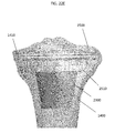
- FIG. 9F shows a front view of one embodiment of a femoral MRD.
- FIG. 10A shows an front view of one embodiment of an IM reamer.
- FIG. 10B shows a bushing assembled with the IM reamer of FIG. 10A .
- FIG. 10C shows a cylindrical reamer assembled with the IM reamer of FIG. 10A .
- FIG. 11 shows a perspective view of one embodiment of a diaphyseal femoral cone.
- FIGS. 12A-B show front and perspective views of an offset bushing attached to the IM reamer of FIG. 10A .
- FIGS. 12C-D show front and perspective views of a conical reamer attached to the instrument of FIGS. 12A-B .
- FIG. 13 shows a perspective view of one embodiment of a metaphyseal femoral cone.
- FIG. 14 shows a front view of a preparatory reaming step of a tibia bone.
- FIG. 15 shows a front view of a cone reamer being prepared for a first reaming step.
- FIG. 16 shows a front view of a first reaming step using the cone reamer of FIG. 15 .
- FIG. 17A shows a front view of a cone trial and reamer guide shaft being prepared for a placing step.
- FIG. 17B shows a perspective view of the cone trial.
- FIG. 17C shows a perspective view demonstrating an interrelation between the cone trial and reamer guide shaft.
- FIG. 18A shows a front view of a placing step and a template guide and sizing template being prepared for a first seating step.
- FIG. 18B shows a perspective view of the sizing template and template guide of FIG. 18A .
- FIG. 19 shows a perspective view of the cone trial, template guide, sizing template, reamer guide shaft and bone after the first seating step has been completed.
- FIG. 20A shows a perspective view of an offset lobe reamer retainer and offset lobe reamer being prepared for a second reaming step.
- FIG. 20B shows a front view of further preparation of the offset lobe reamer and lobe reamer guide for a second reaming step.
- FIG. 21 shows a front view of the surgical reaming system and tibia bone after the second reaming step.
- FIGS. 22A-B show a top and front view of a conical cone, respectively.
- FIGS. 22C-D show a front and side view of an interrelation between the conical cone and a baseplate and baseplate keel.
- FIG. 22E shows a transparent view of an interrelation of the conical cone with the baseplate and baseplate keel when the conical cone is deep within bone.
- FIG. 22F shows a transparent view of an interrelation of the conical cone with the baseplate and baseplate keel when the conical cone is shallow within bone.
- FIGS. 23A-C show a perspective, top, and front view of a lobed cone, respectively.
- FIG. 23D shows a bottom view of an interrelation between a lobed cone and baseplate keel, particularly the relationship of the baseplate keel with regard to a lobe and clearance channel of the lobed cone.
- FIG. 23E shows a transparent view of an interrelation of the lobed cone with the baseplate and baseplate keel when the lobed cone is deep within bone.
- FIG. 23F shows a transparent view of an interrelation of the lobed cone with the baseplate and baseplate keel when the lobed cone is shallow within bone.
- FIG. 23G shows an interrelation between the lobed cone and a stem of a prosthesis.
- proximal means closer to the surgeon or in a direction toward the surgeon and the term “distal” means more distant from the surgeon or in a direction away from the surgeon.
- anterior means towards the front part of the body or the face and the term “posterior” means towards the back of the body.
- medial means toward the midline of the body and the term “lateral” means away from the midline of the body.
- FIG. 1 illustrates a side view of a two part reamer 100 .
- the two part reamer consists of an IM reamer 102 and inline driver 104 .
- longitudinal axes of the IM reamer 102 and inline driver 104 are coaxial.
- the initial step after removing the prosthesis located in the bone is to ream the bone generally along a longitudinal axis thereof.
- the bone is preferably reamed along the IM canal. This can be accomplished, for example, by the use of two part reamer 100 .
- the initial IM reaming step it may be determined that the patient would benefit from a MRD implanted along an axis of the bone offset from the IM axis created in the initial reaming step.
- another drilling step may be performed on the desired axis for MRD implantation.
- FIGS. 2A and 2B illustrate different methods for determining the desired position of the offset axis.
- an alignment guide cutting jig 200 is shown.
- the alignment guide cutting jig 200 can be used to determine the desired location of the offset axis in the bone.
- alignment guide cutting jig 200 is used with an adapter (not shown).
- FIG. 2B shows a cutting block 202 being used in conjunction with the inline driver 104 of the two part reamer 100 to align the offset axis desired for bone 204 .
- the proper offset driver 300 discussed below is chosen to achieve the desired offset axis.
- FIGS. 3A and 3B show an embodiment of an offset driver 300 having a shaft 302 with a longitudinal axis and an adapter end 304 with a longitudinal axis offset from the longitudinal axis of the shaft 302 .
- FIGS. 3A and 3B show offset driver 300 before and after engagement with the IM reamer 102 .
- the offset driver 300 includes a shaft 302 that is offset from the axis of the IM reamer 102 , and thus offset from the axis of the IM canal.
- the offset driver 300 further includes an adapter end 304 at the distal end of the offset driver 300 .
- the adapter end 304 can be at least partially hollow to engage a proximal end of the IM reamer 102 .
- the distal end of the offset driver 300 and the proximal end of the IM reamer 102 can include features to help create a secure engagement between the two.
- the adapter end 304 of offset driver 300 can include a plurality of radially projecting flanges 306 spaced circumferentially around the hollow inside of the adapter end 304 .
- the void spaces between radially projecting flanges 306 can be designed to mate with a set of complementary radially projecting flanges 106 at the proximal end of the IM reamer 102 .
- the offset reamer 400 includes a reaming head 404 and reaming shaft 402 .
- the reaming shaft 402 and reaming head 404 are coaxial with the shaft 302 of the offset driver 300 , and thus are also offset from the axis of the IM reamer 102 .
- a hollow inner cylinder of offset reamer 400 is slipped over the shaft 302 of offset driver 300 to position the reaming head 404 coaxial with the desired offset reaming axis as determined, for example, using a technique described with reference to FIG. 2A or 2B .
- the user can use the offset reamer 400 to create the first offset bone cavity in preparation for MRD implantation.
- FIG. 5A shows an exploded view of an offset reaming guide 500 , offset driver 300 , and IM reamer 102 for optionally forming additional bone cavities that are offset from the offset bone cavity formed by the offset reamer 400 .
- Offset reaming guide 500 includes an offset reaming guide shaft 502 and reaming guide base 504 . As seen in FIG.
- the distal end of reaming guide base 504 can include groove members 508 for locating and engaging with complementary groove members 308 on the proximal end of offset adapter end 304 .
- the groove members 508 of the reaming guide base 504 may be symmetric about the longitudinal axis of the hollow cylindrical interior 510 of the offset reaming guide 500 . This configuration allows the offset reaming guide 500 to be slipped over the shaft 302 of the offset driver 300 and engage the complementary groove members 308 of the offset adapter end 304 in more than one configuration.
- a first engagement position of the offset reaming guide 500 can align the offset reaming guide shaft 502 for preparation of a bone cavity on the medial side of the first offset bone cavity created with offset reamer 400 .
- the same offset reaming guide 500 can then be disengaged from the complementary groove members 308 of the offset adapter end 304 , rotated 180 degrees, and then used to re-engage the complementary groove members 308 of the offset adapter end 304 .
- the offset reaming guide shaft 502 can be aligned on the lateral side of the first offset bone cavity created with the offset reamer 400 .
- FIG. 5C illustrates the offset reaming guide 500 engaged with the offset driver 300 in a first engagement position.
- FIG. 5D illustrates a first medial reaming engagement position of the offset reaming guide 500
- FIG. 5E illustrates a second lateral reaming engagement position of the offset reaming guide 500 .
- the IM reamer 102 is shown in isolation for simplicity of illustration. However, in practice the IM reamer 102 would be engaged within a bone and an operator could change the offset reaming guide 500 from the position shown in FIG. 5D to the position shown in FIG. 5E without removing the IM reamer 102 from the bone. While not shown, the offset reaming guide 500 can be set in a plurality of different positions depending on the choice of the operator.
- the surgical instrument can further be prepared for creating another cavity in the bone, such as a medial or lateral bone cavity that is offset medially or laterally from the offset bone cavity created by the offset reamer 400 .
- FIGS. 6A and 6B show exploded and assembled views of the surgical instrument prepared for creating conical bone cavities, such as medial and lateral bone cavities.
- the IM reamer 102 , offset driver 300 , and offset reaming guide 500 are assembled as seen in FIGS. 5A-E .
- a conical reamer 600 including conical reamer shaft 602 , conical reaming head 604 and conical reamer shaft cavity 610 , is slipped over offset reaming shaft 502 .
- the proximal end of conical reamer shaft cavity 610 (best seen in FIG. 6B ) can include a mating pattern, such as a hexagon, to engage a driver mechanism 650 .
- the driver mechanism (only shown in FIG. 6A ) includes a driver shaft 652 and a driver base 654 .
- the distal end of driver base 654 can include a pattern 660 , such as a hexagon pattern, that is complementary to the mating pattern on the proximal end of conical reamer shaft cavity 610 .
- the operator of the surgical device may drive the conical reamer 600 over the offset reaming guide 500 and into a bone of a patient to create a first conical bone cavity, for example, on the medial side of the initial cylindrical bone cavity created with the offset reamer 400 .
- the operator may disengage the offset reaming guide 500 from the adapter end 304 of the offset driver 300 , and rotate the reaming guide 500 to a second desired position.
- the operator can create a second conical bone cavity, for example, on the lateral side of the initial cylindrical bone cavity created with the offset reamer 400 .
- broaching is an alternative method of preparing a femoral bone cavity.
- FIG. 7A an exploded view of an offset broaching tool 700 , offset driver 300 , and IM reamer 102 is shown.
- the offset broaching tool 700 includes a broaching head 704 and broaching shaft 702 .
- the offset broaching shaft 702 and broaching head 704 are generally coaxial with the shaft 302 of the offset driver 300 , and thus are also offset from the axis of the IM reamer 102 . As seen in FIG.
- a hollow inner cylinder of offset broaching tool 700 is slipped over the shaft 302 of offset driver 300 to position the broaching head 704 coaxial with the desired offset reaming axis as determined, for example, by using a technique described with reference to FIG. 2A or 2B .
- a first offset bone cavity can be created in the bone.
- the broaching tool 700 can be slipped off the offset driver 300 and the surgical tool can be further prepared to create additional bone cavities, such as medial and lateral bone cavities.
- Second stage broaching tool 800 generally includes a shaft 802 and second stage broaching head 804 .
- the second stage broaching head 804 includes a central cylinder shape 805 and a shape comprising two intersecting cones.
- the two intersecting cones generally correspond to a lateral side 806 and medial side 807 (posterior lateral and posterior medial sides best seen in FIG. 8C ) of bone cavities to be created in the bone.
- an operator of the surgical device can create medial and lateral bone cavities about the first offset bone cavity created with the first offset broaching tool 700 , creating a bone cavity that defines the femoral MRD implant geometry with minimal bone removal steps.
- FIG. 9A shows a perspective view of femoral construct 900 of the unlocked variety.
- the femoral construct 900 generally includes a femoral component 902 , offset component 904 , and stem 906 .
- An embodiment of a femoral construct 900 of the locked variety is shown in FIG. 9B .
- the femoral construct 900 further includes a void adapter 908 .
- Both locked and unlocked femoral constructs 900 are capable of accepting the same MRD, such as MRD 910 , for example.
- the locked femoral construct 900 is adapted to mechanically lock the MRD 910 to a femoral implant prior to implantation.
- the MRD would typically be implanted into the corresponding bone cavity prior to implantation of the femoral implant, and would be optionally joined together by use of adhesive, rather than being mechanically locked.
- An assembled locked femoral construct 900 is shown in FIG. 9D with the MRD 910 attached.
- the void adapter 908 can include an external hexagon feature for accepting a wrench for locking the final position of the offset component 904 .
- the distal end of void adapter 908 can also include a male taper with an outer diameter greater than the distance between two diametrically opposed vertices of the hexagon shape. This allows a female taper of the MRD 910 to pass over the external hexagon feature of the void adapter 908 during assembly.
- the void adapter 908 can include a left hand thread on the axis to male taper sized to accept a thread of the offset component 904 to act as a locking nut.
- the femoral construct of the locked variety can include a MRD mechanically locked to a femoral implant with the use of a taper lock feature (best seen in FIG. 9B )
- the femoral construct of the unlocked variety can be assembled with the use of bone cement at the time of implantation, for example. Both locked and unlocked femoral constructs can use the same MRD.
- the locked MRD can be assembled to the femoral component 902 before implantation.
- the unlocked MRD can be implanted before assembly of the femoral component 902 .
- the MRD 910 can include a unique surface cross-section that provides improved load distribution to bone.
- a first group of drilling steps can be performed to create a first cylindrical void space generally coaxial with the IM canal.
- a femoral implant with a diaphyseal femoral cone 1100 (discussed below), that is generally frustoconical, can be implanted into the patient along the bone cavity created in the first group of steps.
- a second group of steps may be performed, building on the first group of steps, to create an appropriate bone cavity.
- FIGS. 10A-C there are shown instruments used in the first group of steps described above.
- an IM reamer 1000 is used to create a first bone cavity generally along the axis of the IM canal.
- a bushing 1010 is slipped over the IM reamer 1000 and used to ream a second bone cavity generally coaxial with the cavity from the first step.
- a cylindrical reamer 1020 is slipped over the IM reamer 1000 and used to ream a third bone cavity generally coaxial to cavities from the first and second steps to prepare the bone to accept a diaphyseal femoral cone, such as diaphyseal femoral cone 1100 illustrated in FIG. 11 . If it is decided at this point that a metaphyseal femoral cone is more appropriate, the diaphyseal femoral cone 1100 is not implanted and two further steps can be completed to prepare the bone to receive a metaphyseal femoral cone.
- FIGS. 12A-D there are shown instruments used in the second group of steps described above.
- an offset driver 1200 is slipped over IM reamer 1000 .
- a conical reamer 1210 is slipped over offset driver 1200 (not visible in FIGS. 12C-D ).
- the offset conical reamer 1210 can then be used to create conical bone cavities that have an axis offset from the bone cavities created in steps 1 - 3 described above. For example, a first conical bone cavity can be created medial to the bone cavity created in steps 1 - 3 .
- a second conical bone cavity can be created lateral to the bone cavity created in steps 1 - 3 .
- the conical bone cavities can be created as necessary to form a complementary fit with a metaphyseal femoral cone, for example metaphyseal femoral cone 1300 illustrated in FIG. 13 .
- FIGS. 14-24 show other embodiment systems and methods for forming voids in bone.
- the beginning of one method of a revision procedure is shown.
- the initial step is to first ream the bone 1400 along the IM canal.
- an elongate IM reamer 1500 is illustrated as distally reaming the tibia beginning at the tibial plateau 1410 , this is merely an example.
- the elongate IM reamer 1500 could also be used to proximally ream the femur beginning at the distal end of the femur in substantially the same manner.
- the elongate IM reamer 1500 includes an elongate IM reamer head 1520 , which is shown positioned within the IM canal, and an elongate reamer shaft 1510 , which is shown extending from the IM canal.
- the elongate IM reamer head 1520 is used for reaming the IM canal and for firmly positioning the elongate IM reamer 1500 within bone 1400 to provide a stable platform for the elongate reamer shaft 1510 to accommodate further components in the knee revision procedure.
- FIG. 15 shows the first step following the initial tibial or femoral IM canal preparation.
- the elongate IM reamer 1500 utilized to initially prepare the IM canal is left in place within the bone 1400 in order to support additional equipment utilized for forming bone voids.
- a hollow inner cylinder of a cone reamer 1600 is slipped over the elongate IM reamer shaft 1510 to position a cone reamer head 1620 coaxial with the elongate IM reamer 1500 .
- the cone reamer head 1620 is generally frustoconical, but may incorporate additional features to accommodate the shape of a void filling implant.
- a neck 1640 may extend from the distal end of the cone reamer head 1620 in order to form a similarly shaped void.
- the cone reamer 1600 also includes a cone reamer shaft 1610 .
- the cone reamer shaft 1610 is configured to be mechanically or manually driven.
- the proximal end of the cone reamer shaft 1610 may be configured to be inserted into a drill chuck.
- a first reaming step is performed by mechanically or manually applying a torque to the cone reamer 1600 to drive the cone reamer head 1620 distally along the elongate IM reamer shaft to form a central bone void that is generally coaxial with the prepared IM canal.
- FIG. 16 shows the positioning of the cone reamer head 1620 within the bone 1400 following the first reaming step. As show in FIG. 16 , the cone reamer head 1620 is driven into the bone such that the proximal surface 1660 of the cone reamer head 1620 is flush with the tibial platform 1410 .
- the surgeon may choose to drive the cone reamer head 1620 deeper into the bone 1400 so that the proximal surface of the cone reamer head 1660 is distal to the tibial platform 1410 .
- This may occur where a surgeon utilizes a tibial or femoral augment to accommodate a medial or lateral bone defect.
- the surgeon may drive the cone reamer head 1620 deeper into the bone 1400 such that the proximal surface of the cone reamer head 1660 is flush with the proximal surface of an augmented bone segment (not shown), but distal to the tibial platform 1410 .
- a cone trial 1700 is shown.
- the cone reamer 1600 first is removed from the created bone void and from engagement with the elongate IM reamer 1500 .
- a cone trial 1700 and a reamer guide shaft 1800 are then slidably engaged with the elongate IM reamer shaft 1510 .
- the cone trial 1700 and reamer guide shaft 1800 may have a hollow inner cylinder that is placed over the elongate IM reamer shaft 1510 in a slidable arrangement.
- FIGS. 17B-C show a perspective view of the cone trial 1700 and the reamer guide shaft 1800 , respectively.
- the cone trial 1700 is generally frustoconical in shape and includes an extraction feature 1730 , anti-rotation splines 1710 , at least one clearance groove 1720 , and a keyway slot 1750 .
- the cone trial 1700 may include other geometric features to substantially match the central bone void.
- the cone trial 1700 may include a cone trial neck 1740 extending from the distal end of the cone trial 1700 .
- the extraction feature 1730 appears as a groove formed on the inner surface of the cone trial, which creates a ridge for engagement with an extraction device.
- One example of such extraction device is the reamer guide shaft 1800 . While this particular embodiment shows a groove forming the extraction feature 1730 , other features not shown may be implemented that allow for the transmission of an axial force to the trial cone 1700 in order to forcibly remove the trial cone 1700 from the central bone void.
- FIG. 17C shows a close-up view of the interrelation between the reamer guide shaft 1800 and cone trial 1700 .
- the reamer guide shaft generally includes a reamer guide shaft body 1830 , a reamer guide shaft impaction surface 1810 , a plurality of locking features 1840 , an orientation key 1870 , and a depth indicator 1860 .
- the impaction surface 1810 is located at the proximal end of the reamer guide shaft body 1830 and is configured to receive and evenly transmit impact forces in an axial direction toward the cone trial 1700 .
- the plurality of locking features 1840 are shown as circular indents located on the outer surface of the reamer guide shaft body 1830 and axially aligned along the longitudinal axis of the reamer guide shaft 1800 .
- the depth indicator 1860 located on the outer surface of the reamer guide shaft body is the depth indicator 1860 , which is shown as a series of notches etched in the outer surface of the reamer guide shaft body 1830 along with corresponding indicator markings.
- a retaining groove 1850 is shown intersecting the depth indicator in a proximal-distal direction.
- the orientation key 1870 Near the distal end of the reamer guide shaft is the orientation key 1870 , which appears as a protrusion extending radially from reamer guide shaft body 1830 .
- the orientation key 1870 is shaped to tightly fit into the orientation keyway slot 1720 of cone trial 1700 to prevent the rotation of the reamer guide shaft 1800 and cone trial 1700 with respect to each other.
- the distal end of the reamer guide shaft 1800 is configured to partially fit within the cone trial 1700 and to mate with an internal ridge 1760 located therein. As shown, the diameter of the internal ridge 1760 is narrower than the outside diameter of the reamer guide 1800 , which facilitates a mating engagement in order to evenly transfer impact forces from the impaction surface 1820 to the cone trial 1700 .
- FIG. 18A shows an inserting step and preparation for a seating step.
- FIG. 18B shows a perspective view of the template guide 2000 and sizing template 1900 .
- the template guide 2000 includes support arms 2020 that selectively attach to the sizing template 1900 .
- the sizing template 1900 has a cavity 1910 that is coaxial with a template guide cavity 2010 .
- the template guide 2000 facilitates manipulation of the sizing template 1900 by the surgeon and also connects the sizing template 1900 to the reamer guide shaft 1800 to prevent rotation of the sizing template 1900 with respect to the reamer guide shaft 1800 .
- FIG. 19 a perspective view of a seating step is shown.
- an engagement feature on the inner surface of the template guide cavity 2010 engages the retaining groove 1850 of the reamer guide shaft 1800 .
- the engagement feature then comes to rest against the distal edge of the retaining groove 1850 .
- the sizing template 1900 and template guide 2000 are restrained from distal and rotational movement, but are free to move along the retaining groove 1850 proximally.
- the cone trial 1700 is fully seated by applying impact force on the impact surface 1810 .
- the appropriate driving depth of the trial cone 1700 is determined by viewing a proximal plateau 2030 of the template guide 2000 in relation to the depth indicator 1860 of the reamer guide shaft 1800 .
- the tibial platform 1410 will engage and push the sizing template 1900 and template guide 2000 proximally along the retaining groove 1850 .
- the surgeon knows the proper depth has been reached.
- the reamer guide shaft 1800 may provide three depths based upon whether a tibial augment is used and the size of the augment. Where no augment is utilized, the cone trial 1700 is driven into the bone 1400 such that the proximal surface of the cone trial 1700 is either flush with the tibial platform 1410 or approximately 1-3 mm distal of the tibial platform, which in this example would be where the proximal plateau 2030 would line up with the most distal marking of the depth indicator 1860 , which is designated as “N”. Once the cone trial 1700 is fully seated within the bone 1400 , the template guide 2000 and sizing template 1900 are removed so that the reamer guide shaft 1800 can be prepared for a second reaming step.
- FIGS. 20A-B illustrate an offset lobe reamer 2200 and offset lobe reamer retainer 2100 and their preparation for the second reaming step to form a first offset lobe void adjacent to the central bone void.
- the offset lobe reamer retainer 2100 includes an offset lobe reamer retainer body 2140 that may be cylindrically hollow, an offset lobe reamer guide 2120 attached to the offset lobe reamer body 2140 by a flange 2130 , and a locking mechanism 2110 .
- the offset lobe reamer guide 2120 has a longitudinal axis that offset from the axis of the IM canal.
- the offset lobe reamer 2200 includes an offset lobe reamer shaft 2210 , an offset lobe reamer head 2220 located at the distal end of the offset lobe reamer shaft 2210 , and a depth stop 2230 near the proximal end of the lobe reamer shaft 2210 .
- the proximal end of the offset lobe reamer 2200 is configured to be manually or mechanically operated.
- the offset lobe reamer 2200 is initially prepared by slidably engaging the offset lobe reamer shaft 2210 with the offset lobe reamer guide 2120 .
- the offset lobe reamer retainer body 2140 is then placed over the reamer guide shaft 1800 such that the offset lobe reamer head 2220 faces the bone 1400 .
- the offset lobe reamer retainer 2100 is then locked at the proper location, which correspondingly fixes the longitudinal axis of the lobe reamer guide 2120 with respect to the longitudinal axis of the IM canal.
- An example of the locking mechanism 2110 is a wingnut that provides a locked connection to the reamer guide shaft 1800 , whereby the threaded screw portion of the locking wingnut engages the circular indents of the locking features 1840 .
- the proper location is determined by selecting a locking position corresponding to a predetermined locking feature 1840 of the reamer guide shaft 1800 .
- the particular embodiment shown in FIGS. 17C and 20A illustrate four separate locking features 1840 , each corresponding to the desired size of the first offset lobe void.
- the locking features 1840 may be designated small, medium, large, and extra-large with the most proximal locking component 1840 being small and most distal being extra-large.
- the more distal the offset lobe reamer retainer 2100 is locked the further the axis of the first offset lobe void will be from the axis of the central bone void. It is also possible to vary the size of the flange 2130 , rather than the locking position to achieve similar results.
- FIG. 21 shows the completion of a second reaming step.
- the surgeon can drive, either mechanically or manually, the offset lobe reamer head 2220 into the bone 1400 , thereby reaming the first offset lobe void adjacent to the central bone void.
- the proper depth of the first offset lobe void can be achieved when the depth stop 2230 abuts the proximal edge of the offset reamer guide 2120 , thereby preventing further distal reaming.
- the first offset lobe void that is formed by the particular embodiment shown in FIG. 21 is integrated with the central bone void to provide the appearance of one continuous void.
- a second offset bone void may be created by repeating the second reaming step on the opposite side of the central bone void.
- Such first and/or second offset bone void may be desirable where there is a bone deformity adjacent to the central bone void. Reaming offset lobe voids would remove the deformity and leave a precisely formed void to be filled with a bone void filler, such as a cone (discussed below), to provide structural integrity to the bone 1400 .
- FIGS. 22-23 illustrate two separate embodiments of the multitude of cones that may be selected.
- FIGS. 23A-F show a conical cone 2300 that is generally frustoconical in shape, but may include a conical cone neck 2320 extending from the distal end of the conical cone 2300 to improve stability. Referring to FIGS. 22A-B , the conical cone 2300 is shown in a top view and front view, respectively.
- the conical cone 2300 generally includes a central opening 2350 to accommodate a prosthesis stem 2520 and at least one clearance channel 2310 to accommodate a baseplate keel 2510 .
- the interior space of the conical cone 2300 formed by the central opening 2350 may be packed with bone cement or other adhesive in order to enhance connection between the prosthesis and bone 1400 .
- This enhanced connection is further improved by an adhesive anti-rotation feature 2340 located on the interior surface of the conical cone 2360 .
- the adhesive anti-rotation feature 2340 may be a series of protrusions extending from the interior surface of the conical cone 2360 to prohibit rotation of the adhesive with respect to the conical cone 2300 .
- the conical cone 2300 may be constructed of any implant-grade material.
- the interior surface of the conical cone 2360 may be constructed of solid titanium, and the exterior surface 2370 constructed of porous titanium to enhance binding bone growth.
- the conical cone 2300 varies in density such that the density decreases from a dense inner surface to a porous outer surface, which would allow for greater bone growth on the outer surface.
- FIGS. 22C-D show a front and side view, respectively, demonstrating the interrelation of the conical cone clearance channel 2310 and baseplate keel 2510 .
- FIGS. 22E-F show transparent views of the interrelation between the conical cone 2300 and baseplate keel 2510 where the conical cone 2300 is implanted at differing bone depths.
- FIG. 22E illustrates the interrelation where the conical cone 2300 is deep within the bone 1400 . This would typically occur where the surgeon utilizes augments to compensate for bone deformities.
- FIG. 22F illustrates the interrelation where the conical cone 2300 is inserted into the central bone void such that the proximal surface of the conical cone 2300 is flush with the tibial platform 1410 .
- FIGS. 23A-G illustrate another cone embodiment.
- the lobed cone 2400 generally includes a central opening 2450 to accommodate a prosthesis stem 2520 , a clearance channel 2420 to accommodate a baseplate keel 2510 , a conical body 2480 , and a lobe 2410 integrated with the conical body 2480 .
- the interior space of the lobed cone 2400 may be packed with bone cement or other adhesive in order to enhance connection between the prosthesis and bone 1400 . This enhanced connection is further improved by an adhesive anti-rotation feature 2450 located on the interior surface of the lobed cone 2460 .
- the adhesive anti-rotation feature 2450 may include a series of protrusions extending from the interior surface of the lobed cone 2460 to prohibit rotation of the adhesive with respect to the lobed cone 2400 .
- the lobed cone 2400 may be constructed of any implant-grade material.
- the interior surface of the lobed cone 2460 may be constructed of solid titanium, and the exterior surface 2470 constructed of porous titanium to enhance binding bone growth.
- Another example would be where the lobed cone 2460 varies in density such that the density decreases from a dense inner surface to a porous outer surface, which would allow for greater bone growth on the outer surface.
- the lobe 2430 may include a window 2430 .
- the window 2430 is essentially a clearance channel 2420 that has been covered by the porous titanium of the outer surface 2470 . This provides the surgeon the flexibility to open the window 2430 by cutting out the porous titanium with standard surgical tools or a specialized tool, thereby creating an additional clearance window 2420 in the event clearance space is needed for a larger baseplate keel 2510 . Where additional clearance space is not needed, the porous titanium remains to provide additional surface area for binding bone growth.
- FIG. 23D is a bottom view illustrating the interrelation of the lobed cone 2400 with the baseplate 2500 and baseplate keel 2510 , and in particular the interrelation of the baseplate keel 2510 with the lobe 2410 and clearance channel 2420 .
- FIGS. 23E-F show transparent views of the interrelation between the lobed cone 2400 and baseplate keel 2510 depending on the depth of the lobed cone 2400 within the bone 1400 .
- FIG. 22E illustrates this interrelation where the lobed cone 2400 is deep within the bone 1400 . This would typically occur where the surgeon utilizes augments to compensate for bone deformities.
- FIG. 23F illustrates the interrelation where the lobed cone 2400 is inserted into the central bone void and offset bone void such that the proximal surface of the lobed cone 2400 is flush with the tibial platform 1410 .
- FIG. 23G shows the prosthesis being inserted into the lobed cone 2400 and bone for final implantation.
- the stem 2600 passes through the central opening 2450 and into the intramedullary canal.
- the baseplate 2500 When fully inserted, the baseplate 2500 will rest proximally to the lobed coned 2400 with the baseplate keel 2510 residing partially within the lobed cone 2400 .
- the lobed cone 2400 will be filled with adhesive to provide further support to the prosthesis.
- the surgical reaming instruments of the present invention there are many benefits of performing a revision procedure with the surgical reaming instruments of the present invention. For example, all bone removal steps may be fully guided without the need for any freehand bone removal. Additionally, the surgeon is left with the option to create an offset bone cavity by reaming the bone in three steps or broaching the bone in only two steps. Importantly, because of the precision of control allowed when using these instruments, the shape of the cavity can be precisely controlled which allows for stock MRDs/cones to accurately fit into the bone void without dependence on the technique of the particular surgeon performing the surgery. Related to this is that the symmetric, geometrically defined shape of an MRD/cone simplifies the setup and machining of void fillers.
- the MRDs/cones described herein can be made of any biocompatible material such as polymer, titanium, and stainless steel, for example.
Landscapes
- Health & Medical Sciences (AREA)
- Life Sciences & Earth Sciences (AREA)
- Surgery (AREA)
- Orthopedic Medicine & Surgery (AREA)
- Veterinary Medicine (AREA)
- General Health & Medical Sciences (AREA)
- Oral & Maxillofacial Surgery (AREA)
- Engineering & Computer Science (AREA)
- Biomedical Technology (AREA)
- Heart & Thoracic Surgery (AREA)
- Public Health (AREA)
- Animal Behavior & Ethology (AREA)
- Molecular Biology (AREA)
- Nuclear Medicine, Radiotherapy & Molecular Imaging (AREA)
- Medical Informatics (AREA)
- Dentistry (AREA)
- Transplantation (AREA)
- Physical Education & Sports Medicine (AREA)
- Cardiology (AREA)
- Vascular Medicine (AREA)
- Surgical Instruments (AREA)
- Prostheses (AREA)
Abstract
Description
Claims (15)
Priority Applications (5)
| Application Number | Priority Date | Filing Date | Title |
|---|---|---|---|
| US15/597,851 US10265083B2 (en) | 2011-12-30 | 2017-05-17 | Systems and methods for preparing bone voids to receive a prosthesis |
| US16/274,684 US11172940B2 (en) | 2011-12-30 | 2019-02-13 | Systems and methods for preparing bone voids to receive a prosthesis |
| US17/496,996 US11877757B2 (en) | 2011-12-30 | 2021-10-08 | Systems and methods for preparing bone voids to receive a prosthesis |
| US18/535,031 US12262899B2 (en) | 2011-12-30 | 2023-12-11 | Systems and methods for preparing bone voids to receive a prosthesis |
| US19/021,374 US20250228573A1 (en) | 2011-12-30 | 2025-01-15 | Systems and Methods For Preparing Bone Voids To Receive A Prosthesis |
Applications Claiming Priority (4)
| Application Number | Priority Date | Filing Date | Title |
|---|---|---|---|
| US201161581736P | 2011-12-30 | 2011-12-30 | |
| US13/730,082 US9149282B2 (en) | 2011-12-30 | 2012-12-28 | Systems and methods for preparing bone voids to receive a prosthesis |
| US14/837,437 US10213215B2 (en) | 2011-12-30 | 2015-08-27 | Systems and methods for preparing bone voids to receive a prosthesis |
| US15/597,851 US10265083B2 (en) | 2011-12-30 | 2017-05-17 | Systems and methods for preparing bone voids to receive a prosthesis |
Related Parent Applications (1)
| Application Number | Title | Priority Date | Filing Date |
|---|---|---|---|
| US14/837,437 Continuation US10213215B2 (en) | 2011-12-30 | 2015-08-27 | Systems and methods for preparing bone voids to receive a prosthesis |
Related Child Applications (1)
| Application Number | Title | Priority Date | Filing Date |
|---|---|---|---|
| US16/274,684 Continuation US11172940B2 (en) | 2011-12-30 | 2019-02-13 | Systems and methods for preparing bone voids to receive a prosthesis |
Publications (2)
| Publication Number | Publication Date |
|---|---|
| US20170246012A1 US20170246012A1 (en) | 2017-08-31 |
| US10265083B2 true US10265083B2 (en) | 2019-04-23 |
Family
ID=47604149
Family Applications (7)
| Application Number | Title | Priority Date | Filing Date |
|---|---|---|---|
| US13/730,082 Active 2033-12-27 US9149282B2 (en) | 2011-12-30 | 2012-12-28 | Systems and methods for preparing bone voids to receive a prosthesis |
| US14/837,437 Active 2034-05-03 US10213215B2 (en) | 2011-12-30 | 2015-08-27 | Systems and methods for preparing bone voids to receive a prosthesis |
| US15/597,851 Active US10265083B2 (en) | 2011-12-30 | 2017-05-17 | Systems and methods for preparing bone voids to receive a prosthesis |
| US16/274,684 Active 2033-11-24 US11172940B2 (en) | 2011-12-30 | 2019-02-13 | Systems and methods for preparing bone voids to receive a prosthesis |
| US17/496,996 Active 2033-06-19 US11877757B2 (en) | 2011-12-30 | 2021-10-08 | Systems and methods for preparing bone voids to receive a prosthesis |
| US18/535,031 Active US12262899B2 (en) | 2011-12-30 | 2023-12-11 | Systems and methods for preparing bone voids to receive a prosthesis |
| US19/021,374 Pending US20250228573A1 (en) | 2011-12-30 | 2025-01-15 | Systems and Methods For Preparing Bone Voids To Receive A Prosthesis |
Family Applications Before (2)
| Application Number | Title | Priority Date | Filing Date |
|---|---|---|---|
| US13/730,082 Active 2033-12-27 US9149282B2 (en) | 2011-12-30 | 2012-12-28 | Systems and methods for preparing bone voids to receive a prosthesis |
| US14/837,437 Active 2034-05-03 US10213215B2 (en) | 2011-12-30 | 2015-08-27 | Systems and methods for preparing bone voids to receive a prosthesis |
Family Applications After (4)
| Application Number | Title | Priority Date | Filing Date |
|---|---|---|---|
| US16/274,684 Active 2033-11-24 US11172940B2 (en) | 2011-12-30 | 2019-02-13 | Systems and methods for preparing bone voids to receive a prosthesis |
| US17/496,996 Active 2033-06-19 US11877757B2 (en) | 2011-12-30 | 2021-10-08 | Systems and methods for preparing bone voids to receive a prosthesis |
| US18/535,031 Active US12262899B2 (en) | 2011-12-30 | 2023-12-11 | Systems and methods for preparing bone voids to receive a prosthesis |
| US19/021,374 Pending US20250228573A1 (en) | 2011-12-30 | 2025-01-15 | Systems and Methods For Preparing Bone Voids To Receive A Prosthesis |
Country Status (4)
| Country | Link |
|---|---|
| US (7) | US9149282B2 (en) |
| EP (1) | EP2797520A1 (en) |
| AU (1) | AU2012362279A1 (en) |
| WO (1) | WO2013102089A1 (en) |
Cited By (6)
| Publication number | Priority date | Publication date | Assignee | Title |
|---|---|---|---|---|
| US20220273319A1 (en) * | 2013-03-13 | 2022-09-01 | Howmedica Osteonics Corp. | Void Filling Joint Prosthesis And Associated Instruments |
| US20220409215A1 (en) * | 2017-12-29 | 2022-12-29 | Depuy Ireland Unlimited Company | Orthopaedic surgical instrument system and method including a stem trial component |
| US11660199B2 (en) | 2020-01-29 | 2023-05-30 | Encore Medical, L.P. | Modular knee augment cones |
| US12121441B2 (en) | 2015-01-12 | 2024-10-22 | Howmedica Osteonics Corp. | Bone void forming apparatus |
| US12262899B2 (en) | 2011-12-30 | 2025-04-01 | Howmedica Osteonics Corp. | Systems and methods for preparing bone voids to receive a prosthesis |
| US12369930B2 (en) | 2022-06-20 | 2025-07-29 | Zimmer, Inc. | Systems for guided reaming of complex shapes |
Families Citing this family (39)
| Publication number | Priority date | Publication date | Assignee | Title |
|---|---|---|---|---|
| US20130041376A1 (en) * | 2011-08-12 | 2013-02-14 | Zimmer, Inc. | Prosthesis resection guide |
| CH705550A1 (en) * | 2011-09-16 | 2013-03-28 | Chirmat Sarl | Surgical tool for boring the diaphyseal canal of long bones. |
| US9011444B2 (en) | 2011-12-09 | 2015-04-21 | Howmedica Osteonics Corp. | Surgical reaming instrument for shaping a bone cavity |
| US9180010B2 (en) | 2012-04-06 | 2015-11-10 | Howmedica Osteonics Corp. | Surface modified unit cell lattice structures for optimized secure freeform fabrication |
| US9636122B2 (en) * | 2013-03-15 | 2017-05-02 | Depuy Ireland Unlimited Company | Femoral orthopaedic instrument assembly for setting offset |
| US20150081028A1 (en) * | 2013-09-18 | 2015-03-19 | Ray Zubok | Adaptor for modular joint prostheses |
| US20150127005A1 (en) * | 2013-11-06 | 2015-05-07 | DePuy Synthes Products, LLC | Clavicle reamer |
| WO2016183446A1 (en) * | 2015-05-13 | 2016-11-17 | Smith & Nephew, Inc. | Anatomically shaped augments |
| CA2979418A1 (en) * | 2015-05-13 | 2016-11-17 | Smith & Nephew, Inc. | System for orthopedic implantation preparation |
| EP3294225B1 (en) | 2015-05-13 | 2024-10-16 | Smith & Nephew, Inc. | Anatomically relieved augments |
| EP3319557B1 (en) * | 2015-07-09 | 2024-02-21 | Waldemar Link GmbH & Co. KG | Sleeve augment device for an articulated joint |
| WO2017005513A2 (en) | 2015-07-09 | 2017-01-12 | Waldemar Link Gmbh & Co. Kg | Hollow sleeve augment device and tool |
| WO2017015371A1 (en) | 2015-07-21 | 2017-01-26 | Smith & Nephew, Inc. | Orthopedic instrumentation |
| US10722372B2 (en) | 2016-07-05 | 2020-07-28 | Howmedica Osteonics Corp. | Hinge knee preparation instrumentation and associated methods |
| AU2018203479B2 (en) | 2017-05-18 | 2024-04-18 | Howmedica Osteonics Corp. | High fatigue strength porous structure |
| WO2018217608A1 (en) * | 2017-05-23 | 2018-11-29 | Biomet Manufacturing, Llc | Offset guide |
| US10987225B2 (en) | 2017-08-04 | 2021-04-27 | Zimmer, Inc. | Systems and methods for attaching sleeve or cone in prosthetic implant having a stem |
| WO2019046579A1 (en) * | 2017-08-31 | 2019-03-07 | Smith & Nephew, Inc. | Intraoperative implant augmentation |
| WO2019075066A1 (en) | 2017-10-11 | 2019-04-18 | Zimmer, Inc. | Impaction cradle |
| CN111212616B (en) * | 2017-10-13 | 2022-04-12 | 捷迈有限公司 | Revision knee arthroplasty methods and instruments |
| US10610365B2 (en) * | 2017-12-23 | 2020-04-07 | Onkos Surgical, Inc. | Implant with ability to capture extravasating fixation medium |
| US11123085B2 (en) | 2018-04-11 | 2021-09-21 | Howmedica Osteonics Corp. | Cutting tool positioned by flexible rod for revision surgery |
| US11684398B2 (en) * | 2019-01-29 | 2023-06-27 | Howmedica Osteonics Corp. | Press fit stem |
| CN114466625B (en) * | 2019-10-03 | 2026-04-10 | 史密夫和内修有限公司 | Intramedullary canal registration during total knee arthroplasty revision |
| US11648016B2 (en) * | 2019-12-28 | 2023-05-16 | Depuy Ireland Unlimited Company | Cannulated, modular femoral broach and surgical instrument handle |
| CN111281477B (en) * | 2020-03-30 | 2024-12-03 | 北京市春立正达医疗器械股份有限公司 | Elbow joint removal instrument |
| IT202000016288A1 (en) | 2020-07-06 | 2022-01-06 | Limacorporate Spa | AUGMENTATION ELEMENT FOR PROSTHESIS, IN PARTICULAR FOR KNEE PROSTHESIS |
| JP7699616B2 (en) * | 2020-07-06 | 2025-06-27 | リマコーポレート・ソチエタ・ペル・アチオニ | Reinforcing elements for knee prostheses |
| US11931082B2 (en) * | 2021-05-11 | 2024-03-19 | Zimmer, Inc. | Surgical instruments with compliant distal stud connection |
| JP2024526886A (en) * | 2021-07-20 | 2024-07-19 | パラゴン28・インコーポレイテッド | Implant Augmentation Systems and Methods of Use |
| US20230190478A1 (en) * | 2021-12-21 | 2023-06-22 | Depuy Ireland Unlimited Company | Orthopaedic knee cone components for use in an orthopaedic surgical procedure and instruments and methods for installing the same |
| US12478477B2 (en) | 2021-12-21 | 2025-11-25 | Depuy Ireland Unlimited Company | Modular tibial cone augments and method of surgically using the same |
| US12115084B2 (en) * | 2021-12-21 | 2024-10-15 | Depuy Ireland Unlimited Company | Method of installing a knee cone augment in an orthopaedic surgical procedure |
| AU2023201401A1 (en) | 2022-03-07 | 2023-09-21 | Howmedica Osteonics Corp. | Hybrid knee prosthesis and methods of use |
| WO2024091349A1 (en) * | 2022-10-24 | 2024-05-02 | Zimmer, Inc. | System of modular reamers and broaches |
| US20240358379A1 (en) * | 2023-04-28 | 2024-10-31 | Howmedica Osteonics Corp. | Total Knee Revision Arthroplasty Implant Kit |
| DE102023113219A1 (en) * | 2023-05-19 | 2024-11-21 | Joimax Gmbh | Spinal milling cutter, spinal milling cutter system and method for machining bone structures in the spinal region |
| WO2025166405A1 (en) * | 2024-02-08 | 2025-08-14 | Signature Orthopaedics Europe Ltd | Osseointegration augment for orthopaedic implants |
| US12458501B1 (en) * | 2025-03-21 | 2025-11-04 | Brian P. Gladnick | De-escalation systems and methods including hip cones for total hip arthroplasty (THA) such as revision total hip arthroplasty |
Citations (119)
| Publication number | Priority date | Publication date | Assignee | Title |
|---|---|---|---|---|
| US3924274A (en) | 1973-07-07 | 1975-12-09 | Friedrichsfeld Gmbh | An adjunct and method for facilitating implantation of joint prostheses |
| US3986212A (en) | 1975-04-11 | 1976-10-19 | Glasrock Products, Inc. | Composite prosthetic device with porous polymeric coating |
| US4065817A (en) | 1975-04-22 | 1978-01-03 | Per Ingvar Branemark | Bone prosthesis and method of forming a bone joint |
| DE2842847A1 (en) | 1978-10-02 | 1980-04-17 | Adolf Dr Med Voorhoeve | Hip joint prosthesis anchor - comprises steel wire between shank and wall of cavity formed in bone |
| EP0016480A1 (en) | 1979-03-15 | 1980-10-01 | GebràDer Sulzer Aktiengesellschaft | Hose-like lining for the anchoring shank of an endoprosthesis |
| US4306550A (en) | 1980-02-06 | 1981-12-22 | Minnesota Mining And Manufacturing Company | Combination including femoral rasp and calcar facing reamer |
| US4341206A (en) | 1978-12-19 | 1982-07-27 | Synthes Ag | Device for producing a hole in a bone |
| US4463444A (en) | 1981-10-26 | 1984-07-31 | International Business Machines Corporation | Word processing system having a formatting bidirectional printer |
| US4549319A (en) | 1982-08-03 | 1985-10-29 | United States Medical Corporation | Artificial joint fixation to bone |
| GB2159416A (en) | 1984-06-01 | 1985-12-04 | Raymond G Tronzo | Adjustable acetabular cup prosthesis as part of a total cup replacement system |
| US4693721A (en) | 1984-10-17 | 1987-09-15 | Paul Ducheyne | Porous flexible metal fiber material for surgical implantation |
| US4728335A (en) | 1986-12-15 | 1988-03-01 | Jurgutis John A | Hip prosthesis |
| US4735625A (en) | 1985-09-11 | 1988-04-05 | Richards Medical Company | Bone cement reinforcement and method |
| US4738256A (en) | 1985-06-26 | 1988-04-19 | Finsbury (Instruments) Limited | Surgical tool |
| US4751922A (en) | 1986-06-27 | 1988-06-21 | Dipietropolo Al | Flexible medullary reamer |
| US4777942A (en) | 1986-10-02 | 1988-10-18 | Sulzer Brothers Limited | Bone milling instrument |
| US4790852A (en) | 1986-09-15 | 1988-12-13 | Joint Medical Products Corporation | Sleeves for affixing artificial joints to bone |
| US4822366A (en) | 1986-10-16 | 1989-04-18 | Boehringer Mannheim Corporation | Modular knee prosthesis |
| US4846839A (en) | 1984-02-09 | 1989-07-11 | Joint Medical Products Corporation | Apparatus for affixing a prosthesis to bone |
| US4997448A (en) | 1989-02-13 | 1991-03-05 | Feiler Frederic C | Proximal cement sealing plug for hip prosthesis |
| US5006121A (en) | 1990-04-23 | 1991-04-09 | Artifex Ltd. | Bone broaches and methods of manufacturing thereof |
| US5011496A (en) | 1988-02-02 | 1991-04-30 | Joint Medical Products Corporation | Prosthetic joint |
| US5035717A (en) | 1988-05-12 | 1991-07-30 | Brooks Peter J | Insert and method of using same |
| US5047033A (en) | 1989-02-08 | 1991-09-10 | Smith & Nephew Richards Inc. | Mill and guide apparatus for preparation of a hip prosthesis |
| US5049157A (en) | 1978-06-29 | 1991-09-17 | Osteo Ag | Reinforced bone cement |
| US5061287A (en) | 1989-02-13 | 1991-10-29 | Feiler Frederic C | Proximal cement sealing plug for hip prosthesis |
| US5089004A (en) | 1988-01-19 | 1992-02-18 | Osteonics Corp. | Prosthetic implant procedure and femoral broach therefor |
| US5122134A (en) | 1990-02-02 | 1992-06-16 | Pfizer Hospital Products Group, Inc. | Surgical reamer |
| US5152797A (en) | 1991-10-25 | 1992-10-06 | Johnson & Johnson Orthopaedics, Inc. | Modular prosthesis |
| US5169402A (en) | 1988-10-08 | 1992-12-08 | Chas. F. Thackray Ltd. | Surgical instrument |
| US5190548A (en) | 1991-04-10 | 1993-03-02 | Linvatec Corporation | Surgical reamer |
| US5192283A (en) | 1990-08-10 | 1993-03-09 | Ling Robin S M | System for performing hip prosthesis revision surgery |
| US5342366A (en) | 1992-02-19 | 1994-08-30 | Biomet, Inc. | Surgical instruments for hip revision |
| US5342363A (en) | 1992-11-30 | 1994-08-30 | Wright Medical Technology, Inc. | Medical instrument and procedure |
| US5387218A (en) | 1990-12-06 | 1995-02-07 | University College London | Surgical instrument for shaping a bone |
| US5403320A (en) | 1993-01-07 | 1995-04-04 | Venus Corporation | Bone milling guide apparatus and method |
| US5441501A (en) | 1994-06-20 | 1995-08-15 | Zimmer, Inc. | Intermedullary rasp with detachable extension end |
| US5445642A (en) | 1992-09-01 | 1995-08-29 | Depuy Inc. | Method for installing a femoral component |
| US5480453A (en) | 1992-11-20 | 1996-01-02 | Burke; Dennis W. | Collar for femoral implant and method and apparatus for installation thereof |
| US5489311A (en) | 1994-01-21 | 1996-02-06 | Joint Medical Products Corporation | Prosthesis with orientable bearing surface |
| US5496324A (en) | 1994-06-20 | 1996-03-05 | Zimmer, Inc. | Proximal body milling apparatus |
| US5507832A (en) | 1993-10-26 | 1996-04-16 | Howmedica, Inc. | Prosthesis with integral proximal spacer |
| US5527316A (en) | 1994-02-23 | 1996-06-18 | Stone; Kevin T. | Surgical reamer |
| US5534005A (en) | 1994-10-05 | 1996-07-09 | Smith & Nephew Richards, Inc. | Surgical milling system |
| US5540694A (en) | 1993-06-01 | 1996-07-30 | Joint Medical Products Corporation | Instrument for cutting bone |
| US5591233A (en) | 1990-06-01 | 1997-01-07 | Depuy Dupont Orthopaedics | Metal/composite hybrid orthopedic implants |
| US5649299A (en) | 1993-10-27 | 1997-07-15 | Motorola, Inc. | Apparatus and method for adapting a digital radiotelephone system to increased subscriber traffic |
| US5674223A (en) * | 1994-02-16 | 1997-10-07 | Joint Medical Products Corporation | Instrument for implanting a femoral knee prosthesis |
| US5755793A (en) | 1996-09-04 | 1998-05-26 | Bristol-Myers Squibb Company | Centralizer for a prosthetic implant |
| US5755720A (en) | 1997-01-03 | 1998-05-26 | Mikhail Michael W E | Method and apparatus for performing hip prosthesis surgery |
| US5766261A (en) | 1996-02-01 | 1998-06-16 | Osteonics Corp. | Femoral revision broach with modular trial components and method |
| US5782921A (en) | 1996-07-23 | 1998-07-21 | Johnson & Johnson Professional, Inc. | Modular knee prosthesis |
| US5824097A (en) | 1996-07-23 | 1998-10-20 | Johnson & Johnson Professional, Inc. | Medical fastening system |
| US5931841A (en) | 1998-04-24 | 1999-08-03 | Stryker Technologies Corporation | Combination broacher-reamer for use in orthopaedic surgery |
| US5951603A (en) | 1997-09-25 | 1999-09-14 | Johnson & Johnson Professional, Inc. | Rotatable joint prosthesis with axial securement |
| US5957925A (en) | 1998-05-20 | 1999-09-28 | Bristol-Myers Squibb Co. | Orthopaedic milling instrument |
| US5976145A (en) | 1998-06-01 | 1999-11-02 | Johnson & Johnson Professional, Inc. | Calcar milling guide and system |
| US5976147A (en) | 1997-07-11 | 1999-11-02 | Johnson & Johnson Professional, Inc | Modular instrumentation for bone preparation and implant trial reduction of orthopedic implants |
| US5984968A (en) | 1995-09-29 | 1999-11-16 | Park; Joon B. | Reinforcement for an orthopedic implant |
| US5989261A (en) | 1997-03-13 | 1999-11-23 | Zimmer, Ltd. | Evaluating the fit of an orthopaedic implant |
| US5989257A (en) | 1998-03-11 | 1999-11-23 | Midas Rex L.P. | Redundant safety lock mechanism |
| US5993455A (en) | 1996-11-13 | 1999-11-30 | Noble; Philip C. | Surgical broach and methods for preparing the medullary cavity of a femur in hip arthroplasty |
| US6010534A (en) | 1997-09-25 | 2000-01-04 | Johnson & Johnson Professional, Inc. | Rotatable tibial prosthesis with keyed axial securement |
| US6045556A (en) | 1996-11-08 | 2000-04-04 | Depuy International, Ltd. | Broach for shaping a medullary cavity in a bone |
| US6053945A (en) | 1997-09-25 | 2000-04-25 | Johnson & Johnson Professional, Inc. | Joint prosthesis having controlled rotation |
| US6071311A (en) | 1998-08-14 | 2000-06-06 | Johnson & Johnson Professional, Inc. | Cylindrical box femoral stem |
| US6139584A (en) | 1998-12-22 | 2000-10-31 | Depuy Orthopaedics, Inc. | Proximal femoral sleeve for a revision hip prosthesis |
| US6152963A (en) | 1996-01-04 | 2000-11-28 | Joint Medical Products Corporation | Method and apparatus for fitting a prosthesis to a bone |
| US6171342B1 (en) | 1996-07-23 | 2001-01-09 | Depuy Orthopaedics, Inc. | Medical fastening system |
| US6214053B1 (en) | 1998-06-04 | 2001-04-10 | Benoist Girard Sas | Prosthesis with centralizer and centralizer for use therewith |
| US6214052B1 (en) | 1999-01-19 | 2001-04-10 | Sulzer Orthopedics Inc. | Tibial component with a reversible, adjustable stem |
| US6241722B1 (en) | 1998-06-17 | 2001-06-05 | Cryogen, Inc. | Cryogenic device, system and method of using same |
| US6245113B1 (en) | 1998-10-08 | 2001-06-12 | Johnson & Johnson Medical Ltd. | Centralizer |
| US20020016634A1 (en) | 2000-07-28 | 2002-02-07 | Brian Maroney | Device and method for positioning an eccentric humeral head of a humerus prothesis for a shoulder arthroplasty |
| US6440171B1 (en) | 2001-02-27 | 2002-08-27 | Hammill Manuf. Co. | Double D key locking prosthesis |
| US6494913B1 (en) | 1998-03-17 | 2002-12-17 | Acumed, Inc. | Shoulder prosthesis |
| US20030171756A1 (en) | 2002-02-12 | 2003-09-11 | Fallin T. Wade | Surgical milling instrument for shaping a bone cavity |
| WO2003094698A2 (en) | 2002-05-09 | 2003-11-20 | Hayes Medical, Inc. | Bone milling instrument |
| US20040049285A1 (en) | 2002-09-09 | 2004-03-11 | Brian Haas | Duo-fixation prosthetic joints |
| US20040162619A1 (en) | 2001-08-27 | 2004-08-19 | Zimmer Technology, Inc. | Tibial augments for use with knee joint prostheses, method of implanting the tibial augment, and associated tools |
| US6887276B2 (en) | 2002-12-13 | 2005-05-03 | Medicine Lodge, Inc | Modular implant for joint reconstruction and method of use |
| US6945556B2 (en) | 2002-11-29 | 2005-09-20 | Takata Restraint Systems, Inc. | Airbag fabric diffuser |
| US20050288676A1 (en) | 2004-06-29 | 2005-12-29 | Barry Schnieders | Minimally invasive bone broach |
| US20060147332A1 (en) | 2004-12-30 | 2006-07-06 | Howmedica Osteonics Corp. | Laser-produced porous structure |
| US7074224B2 (en) | 2003-06-25 | 2006-07-11 | Depuy Products, Inc. | Modular tapered reamer for bone preparation and associated method |
| US7112203B2 (en) | 2002-05-23 | 2006-09-26 | Centerpulse Orthopedics Ltd. | Apparatus for the preparation of a femur bone for the implantation of a prosthesis |
| WO2006127486A2 (en) | 2005-05-20 | 2006-11-30 | Smith & Nephew, Inc. | Patello-femoral joint implant and instrumentation |
| US20070088443A1 (en) | 2001-08-27 | 2007-04-19 | Hanssen Arlen D | Prosthetic implant support structure |
| US20070118229A1 (en) | 2004-05-28 | 2007-05-24 | Smith & Nephew, Inc. | Fluted sleeve hip prosthesis for modular stem |
| US20070142914A1 (en) | 2005-12-06 | 2007-06-21 | Eric Jones | Laser-produced porous surface |
| US20070225821A1 (en) | 2006-03-21 | 2007-09-27 | Axiom Orthopaedics, Inc. | Femoral and humeral stem geometry and implantation method for orthopedic joint reconstruction |
| US7291174B2 (en) | 2002-09-09 | 2007-11-06 | Depuy Products, Inc. | Prosthetic tibial component with modular sleeve |
| WO2008069800A1 (en) | 2006-12-07 | 2008-06-12 | Anatol Podolsky | Method and apparatus for total hip replacement |
| US7393355B2 (en) | 2003-02-04 | 2008-07-01 | Howmedica Osteonics Corp. | Femoral guide and pivoting reamer |
| US7481814B1 (en) | 2003-07-28 | 2009-01-27 | Biomet Manufacturing Corporation | Method and apparatus for use of a mill or reamer |
| US7537664B2 (en) | 2002-11-08 | 2009-05-26 | Howmedica Osteonics Corp. | Laser-produced porous surface |
| US20090157190A1 (en) | 2007-12-13 | 2009-06-18 | Howmedica Inc. | Osteotomy spacer |
| US20100076565A1 (en) | 2008-06-03 | 2010-03-25 | Depuy Products, Inc. | Porous Titanium Femoral Sleeves and Their Use in Revision Knee Surgery |
| EP2168586A1 (en) | 2007-05-23 | 2010-03-31 | Viktor Ivanovich Roschin | Active ingredient of a medicinal agent, a medicinal agent, a pharmaceutical composition and method for treating dementia syndrome patients |
| US20100082031A1 (en) | 2008-09-30 | 2010-04-01 | Sackett Samuel G | Minimally invasive bone miller apparatus |
| EP2181672A1 (en) | 2008-10-31 | 2010-05-05 | DePuy Products, Inc. | Knee prosthesis kit with a winged metaphyseal sleeve |
| US7785328B2 (en) | 2003-12-30 | 2010-08-31 | Depuy Products, Inc. | Minimally invasive bone miller apparatus |
| US20100222891A1 (en) | 2003-11-18 | 2010-09-02 | Depuy Products, Inc. | Modular implant system with fully porous coated sleeve |
| US20100262146A1 (en) * | 2009-04-09 | 2010-10-14 | Howmedica Osteonics Corp. | Disposable bone cutting instrument |
| US7833228B1 (en) | 2004-01-05 | 2010-11-16 | Biomet Manufacturing Corp. | Method and instrumentation for performing minimally invasive hip arthroplasty |
| US7892288B2 (en) | 2001-08-27 | 2011-02-22 | Zimmer Technology, Inc. | Femoral augments for use with knee joint prosthesis |
| US20110190899A1 (en) | 2006-02-27 | 2011-08-04 | Biomet Manufacturing Corp. | Patient-specific augments |
| US20120016482A1 (en) | 2010-07-14 | 2012-01-19 | Howmedica Osteonics Corp. | Prosthetic knee void filers with splined fixation |
| US8147861B2 (en) | 2006-08-15 | 2012-04-03 | Howmedica Osteonics Corp. | Antimicrobial implant |
| US20120089146A1 (en) * | 2010-10-06 | 2012-04-12 | Howmedica Osteonics Corp. | System and method of bone preparation |
| US8177788B2 (en) | 2005-02-22 | 2012-05-15 | Smith & Nephew, Inc. | In-line milling system |
| US8187336B2 (en) | 2003-06-16 | 2012-05-29 | Jamali Amir A | Device and method for reconstruction of osseous skeletal defects |
| US8350186B2 (en) | 2005-12-30 | 2013-01-08 | Howmedica Osteonics Corp. | Laser-produced implants |
| US8372157B2 (en) | 2007-02-12 | 2013-02-12 | Warsaw Orthopedic, Inc. | Joint revision implant |
| US8382849B2 (en) | 2008-06-03 | 2013-02-26 | DePuy Synthes Products, LLC | Porous titanium tibial sleeves and their use in revision knee surgery |
| US20130053976A1 (en) | 2010-05-07 | 2013-02-28 | Jossi Holding Ag | Method for Producting an Implant and Implant Having at Least One Break Line |
| US8444699B2 (en) | 2010-02-18 | 2013-05-21 | Biomet Manufacturing Corp. | Method and apparatus for augmenting bone defects |
| US20130150858A1 (en) * | 2011-12-09 | 2013-06-13 | Howmedica Osteonics Corp. | Surgical reaming instrument for shaping a bone cavity |
| US8585770B2 (en) | 2011-07-12 | 2013-11-19 | Biomet Manufacturing, Llc | Implant sleeve for cement hip stems |
Family Cites Families (102)
| Publication number | Priority date | Publication date | Assignee | Title |
|---|---|---|---|---|
| GB1421366A (en) | 1972-05-04 | 1976-01-14 | Saratovsky G Meditsninsky I | Artificial hip-joint |
| US4301553A (en) | 1975-08-15 | 1981-11-24 | United States Surgical Corporation | Prosthetic knee joint |
| US3979778A (en) | 1976-01-14 | 1976-09-14 | Stroot Jerome H | Shoulder prosthesis |
| US4045825A (en) | 1976-01-28 | 1977-09-06 | Stroot Jerome H | Humerus prosthesis |
| US4158893A (en) | 1976-10-12 | 1979-06-26 | Swanson Alfred B | Protective sleeve for implantable prosthesis and method of protecting the prosthesis |
| DE7634751U1 (en) | 1976-11-02 | 1977-05-05 | Omar-Pacha, Nabil, Dr.Dr., 3470 Hoexter | Knee joint prosthesis |
| US4045826A (en) | 1977-02-09 | 1977-09-06 | Stroot Jerome H | Glenoid component for shoulder prosthesis |
| DE2925145C2 (en) | 1979-06-22 | 1982-07-22 | Wolfgang Dr. 4900 Herford Schneider | "Shoulder joint head endoprosthesis" |
| DE3435243C1 (en) | 1984-09-26 | 1986-03-13 | S + G Implants GmbH, 2400 Lübeck | Femoral prosthesis part of a knee joint endoprosthesis |
| DE3507155C2 (en) | 1985-03-01 | 1986-12-11 | S + G Implants GmbH, 2400 Lübeck | Fastening element for ligaments on the tibial part of a knee joint endoprosthesis |
| EP0220803A3 (en) | 1985-09-16 | 1987-10-21 | Dow Corning Corporation | Multiple component hip femoral prosthesis |
| US5080685A (en) | 1986-08-15 | 1992-01-14 | Boehringer Mannheim Corporation | Modular hip prosthesis |
| US4950298A (en) | 1988-04-08 | 1990-08-21 | Gustilo Ramon B | Modular knee joint prosthesis |
| US4944757A (en) | 1988-11-07 | 1990-07-31 | Martinez David M | Modulator knee prosthesis system |
| US5061271A (en) | 1989-02-27 | 1991-10-29 | Boehringer Mannheim Corporation | Tool for separating components of a modular joint prosthesis |
| US5108398A (en) | 1990-10-16 | 1992-04-28 | Orthopaedic Research Institute | Orthopaedic knee fusion apparatus |
| FR2685633B1 (en) | 1991-12-27 | 1998-02-27 | Tornier Sa | MODULAR HUMER PROSTHESIS. |
| US7722678B2 (en) | 1993-11-01 | 2010-05-25 | Biomet Manufacturing Corp. | Intramedullary compliant fixation |
| US7670383B1 (en) | 2004-05-04 | 2010-03-02 | Biomet Manufacturing Corp. | Pubic catch |
| US6197065B1 (en) | 1993-11-01 | 2001-03-06 | Biomet, Inc. | Method and apparatus for segmental bone replacement |
| US7141073B2 (en) | 1993-11-01 | 2006-11-28 | Biomet, Inc. | Compliant fixation of external prosthesis |
| US7476254B2 (en) | 1993-11-01 | 2009-01-13 | Biomet Manufacturing Corporation | Compliant fixation for pelvis |
| US5507817A (en) | 1994-02-22 | 1996-04-16 | Kirschner Medical Corporation | Modular humeral prosthesis for reconstruction of the humerus |
| US5411505A (en) | 1994-06-02 | 1995-05-02 | Intermedics Orthopedics, Inc. | Sagittal saw jig for femoral knee revision prosthesis |
| FR2727857B1 (en) | 1994-12-08 | 1997-01-24 | Cedior | TOTAL SHOULDER PROSTHESIS |
| US5609641A (en) | 1995-01-31 | 1997-03-11 | Smith & Nephew Richards Inc. | Tibial prosthesis |
| US5634927A (en) | 1995-07-06 | 1997-06-03 | Zimmer, Inc. | Sizing plate and drill guide assembly for orthopaedic knee instrumentation |
| US5906644A (en) | 1996-08-30 | 1999-05-25 | Powell; Douglas Hunter | Adjustable modular orthopedic implant |
| GB9620998D0 (en) | 1996-10-09 | 1996-11-27 | Minnesota Mining & Mfg | Shoulder prosthesis |
| FR2773469B1 (en) | 1998-01-09 | 2000-03-03 | Alain Leonard | SURGICAL EQUIPMENT FOR THE IMPLANTATION OF A TOTAL SHOULDER PROSTHESIS, AND TOTAL SHOULDER PROSTHESIS |
| DE29800975U1 (en) | 1998-01-22 | 1999-05-27 | Rüter, Axel, Prof. Dr., 86356 Neusäß | Humeral head prosthesis |
| US6127596A (en) | 1998-01-23 | 2000-10-03 | Sulzer Orthopedics Inc. | Implantable orthopedic prosthesis having tissue attachment surface and method of manufacture |
| US6226542B1 (en) | 1998-07-24 | 2001-05-01 | Biosense, Inc. | Three-dimensional reconstruction of intrabody organs |
| US6264699B1 (en) | 1998-11-23 | 2001-07-24 | Depuy Orthopaedics, Inc. | Modular stem and sleeve prosthesis |
| US6283999B1 (en) | 1999-01-29 | 2001-09-04 | Depuy Orthopaedics, Inc. | Shoulder prothesis with humeral fracture stem |
| IT1317744B1 (en) | 2000-01-28 | 2003-07-15 | Cremascoli Ortho S A | ENDOPROTESIS OF THE SHOULDER FOR FRACTURES OF THE UPPER HUMERUM END. |
| US6398812B1 (en) | 2000-02-10 | 2002-06-04 | Medidea, Llc | Shoulder prosthesis with anatomic reattachment features |
| US6613092B1 (en) | 2000-07-19 | 2003-09-02 | Centerpulse Orthopedics Inc. | Stem taper adapter |
| US6592622B1 (en) | 2000-10-24 | 2003-07-15 | Depuy Orthopaedics, Inc. | Apparatus and method for securing soft tissue to an artificial prosthesis |
| WO2002039932A1 (en) | 2000-11-16 | 2002-05-23 | Willi Horber | Joint prosthesis |
| US6620197B2 (en) | 2001-01-23 | 2003-09-16 | Depuy Orthopaedics, Inc. | Method and apparatus for performing a shoulder replacement procedure in the treatment of cuff tear arthropathy |
| US6663670B2 (en) | 2002-01-18 | 2003-12-16 | Depuy Orthopaedics, Inc. | Adjustable long bone prosthesis |
| US6949101B2 (en) | 2002-03-29 | 2005-09-27 | Depuy Orthopaedics, Inc. | Medical instrument for milling a curved path in bone and procedure |
| US6902583B2 (en) | 2002-04-25 | 2005-06-07 | Medicinelodge, Inc. | Tripartite attachment mechanism and method for a modular prosthesis |
| US20030204267A1 (en) | 2002-04-30 | 2003-10-30 | Hazebrouck Stephen A. | Modular limb preservation system |
| US7070622B1 (en) | 2002-07-03 | 2006-07-04 | Biomet, Inc. | Prosthesis having a modular soft tissue fixation mechanism |
| US7175664B1 (en) | 2002-07-03 | 2007-02-13 | Biomet, Inc. | Prosthetic having a modular soft tissue fixation mechanism |
| US6905513B1 (en) | 2002-08-30 | 2005-06-14 | Biomet, Inc. | Knee prosthesis with graft ligaments |
| US7338528B2 (en) | 2003-02-04 | 2008-03-04 | Biomet Manufacturing Corp. | Humeral stem with anatomical location of taper access for fixation of humeral head |
| US20040267267A1 (en) | 2003-06-25 | 2004-12-30 | Daniels David Wayne | Non-linear reamer for bone preparation and associated method |
| US7615080B2 (en) | 2003-06-30 | 2009-11-10 | Depuy Products, Inc. | Joint prosthesis having infinitely adjustable head |
| DE602004022870D1 (en) | 2004-02-05 | 2009-10-08 | Exactech Inc | |
| US8048166B2 (en) | 2004-05-04 | 2011-11-01 | Biomet Manufacturing Corp. | Method and apparatus for constructing a modular acetabulum |
| FR2871371B1 (en) | 2004-06-15 | 2007-04-06 | Tornier Sas | GLENOIDAL COMPONENT OF SHOULDER PROSTHESIS, SET OF COMPONENT ELEMENTS OF SUCH COMPONENT AND TOTAL SHOULDER PROSTHESIS INCORPORATING SUCH COMPONENT |
| US7481841B2 (en) | 2004-06-30 | 2009-01-27 | Depuy Products, Inc. | Adjustable orthopaedic prosthesis and associated method |
| US7832405B1 (en) | 2004-08-25 | 2010-11-16 | Biomet Manufacturing Corp. | Method and apparatus for assembling implants |
| US7507256B2 (en) | 2004-12-17 | 2009-03-24 | Depuy Products, Inc. | Modular implant system and method with diaphyseal implant |
| US7998217B1 (en) | 2005-02-02 | 2011-08-16 | Biomet Manufacturing Corp. | Modular offset stem implants |
| US7445638B2 (en) | 2005-03-03 | 2008-11-04 | Biomet France | Humeral implant for shoulder prosthesis |
| US8292967B2 (en) | 2005-04-21 | 2012-10-23 | Biomet Manufacturing Corp. | Method and apparatus for use of porous implants |
| US20080051908A1 (en) | 2006-08-22 | 2008-02-28 | Laurent Angibaud | System and method for adjusting the thickness of a prosthesis |
| US8052687B2 (en) | 2006-09-29 | 2011-11-08 | Depuy Products, Inc. | Calcar planar |
| CN101652114B (en) | 2006-10-04 | 2012-03-21 | 史密夫和内修有限公司 | Apparatus and method for distal resection of knee repair |
| US7806936B2 (en) | 2006-10-19 | 2010-10-05 | Depuy Products, Inc. | Bowed femoral sleeve |
| JP5448842B2 (en) | 2007-01-10 | 2014-03-19 | バイオメト マニファクチャリング コーポレイション | Knee joint prosthesis system and implantation method |
| US8177849B2 (en) | 2007-05-07 | 2012-05-15 | Zimmer, Inc. | Methods and apparatuses for attaching tissue to orthopaedic implants |
| US20080281428A1 (en) | 2007-05-07 | 2008-11-13 | Zimmer, Inc. | Methods and apparatuses for attaching soft tissue to orthopaedic implants |
| DE102007028087B4 (en) | 2007-06-11 | 2014-05-15 | Aesculap Ag | Modular implant part and knee joint prosthesis |
| US20090088862A1 (en) | 2007-09-27 | 2009-04-02 | Kyle Thomas | Stem extension and adaptor for use with a knee orthopaedic implant |
| US8273091B2 (en) | 2007-10-04 | 2012-09-25 | Ebi, Llc | Alignment device for locking nail |
| AU2009200262B1 (en) | 2008-01-30 | 2009-06-11 | Top Idea Australia Pty Ltd | Modular angle trim |
| US8118868B2 (en) | 2008-04-22 | 2012-02-21 | Biomet Manufacturing Corp. | Method and apparatus for attaching soft tissue to an implant |
| US8337498B2 (en) | 2008-08-13 | 2012-12-25 | Rasmussen G Lynn | Systems and methods for providing a bone milling device |
| US20110213467A1 (en) | 2009-01-20 | 2011-09-01 | Zimmer, Inc. | Orthopaedic implant with woven ingrowth material |
| US20110130840A1 (en) | 2009-05-20 | 2011-06-02 | Oskouei Shervin V | Soft tissue attachment device and method |
| US20110015634A1 (en) | 2009-07-14 | 2011-01-20 | Biomet Manufacturing Corp. | Modular Reaming System for Femoral Revision |
| US8182542B2 (en) | 2009-09-01 | 2012-05-22 | Howmedica Osteonics Corp. | Soft tissue attachment mechanism |
| US8226725B2 (en) | 2009-09-01 | 2012-07-24 | Howmedica Osteonics Corp. | Prosthesis having a soft tissue attachment element |
| US8403935B2 (en) | 2009-11-10 | 2013-03-26 | Wright Medical Technology, Inc. | Adjustable revision guide |
| KR20120112470A (en) | 2009-11-20 | 2012-10-11 | 니 크리에이션스, 엘엘씨 | Instruments for targeting a joint defect |
| US8679130B2 (en) | 2010-03-05 | 2014-03-25 | Biomet Manufacturing, Llc | Guide assembly for lateral implants and associated methods |
| US8460393B2 (en) | 2010-03-05 | 2013-06-11 | Biomet Manufacturing Corp. | Modular lateral hip augments |
| US8715356B2 (en) | 2010-04-13 | 2014-05-06 | Biomet Manufacturing, Llc | Prosthetic having a modular soft tissue fixation mechanism |
| DE102010044571A1 (en) | 2010-09-07 | 2012-03-08 | Implantcast Gmbh | base graft |
| US8709092B2 (en) | 2011-02-16 | 2014-04-29 | Genesis Medical Devices, LLC | Periprosthetic fracture management enhancements |
| CN103841925B (en) | 2011-03-16 | 2017-02-15 | 史密夫和内修有限公司 | Compound Angle Implants |
| AU2012258998B2 (en) | 2011-05-20 | 2016-05-05 | Zimmer, Inc. | Stabilizing prosthesis support structure |
| US9149282B2 (en) | 2011-12-30 | 2015-10-06 | Howmedica Osteonics Corp. | Systems and methods for preparing bone voids to receive a prosthesis |
| EP2802363B1 (en) | 2012-01-09 | 2018-10-24 | Zimmer, Inc. | Composite device that combines porous metal and bone stimuli |
| US9795392B2 (en) | 2012-02-06 | 2017-10-24 | Arthrex, Inc. | Surgical instrumentation set and surgical technique |
| US9180010B2 (en) | 2012-04-06 | 2015-11-10 | Howmedica Osteonics Corp. | Surface modified unit cell lattice structures for optimized secure freeform fabrication |
| US9135374B2 (en) | 2012-04-06 | 2015-09-15 | Howmedica Osteonics Corp. | Surface modified unit cell lattice structures for optimized secure freeform fabrication |
| US9320527B2 (en) | 2013-01-18 | 2016-04-26 | Biomet Manufacturing, Llc | Quick-connect anti-rotation peg/drill bit component |
| US9526513B2 (en) | 2013-03-13 | 2016-12-27 | Howmedica Osteonics Corp. | Void filling joint prosthesis and associated instruments |
| US10596009B2 (en) | 2013-03-15 | 2020-03-24 | Smith & Nephew, Inc. | Knee augment |
| US9089375B2 (en) | 2013-10-12 | 2015-07-28 | Interfix, Llc | Combined intramedullary and extramedullary surgical aiming system and method |
| US20150282935A1 (en) | 2014-04-04 | 2015-10-08 | Biomet Trauma, LLC | Intramedullary device for treating periprosthetic fractures |
| US9498343B2 (en) | 2014-07-25 | 2016-11-22 | Russell Nevins | Implant system for knee prosthesis |
| US10149763B2 (en) | 2015-01-12 | 2018-12-11 | Howmedica Osteonics Corp. | Multipurpose void filling prosthesis |
| US9597190B2 (en) | 2015-01-15 | 2017-03-21 | DePuy Synthes Products, Inc. | Modular reverse shoulder orthopaedic implant and method of implanting the same |
| AU2019203591B2 (en) | 2018-05-25 | 2024-11-14 | Howmedica Osteonics Corp. | Variable thickness femoral augments |
| GB2596576B (en) | 2020-07-01 | 2024-07-24 | Matortho Ltd | A revision-implant receiver and method of use thereof |
-
2012
- 2012-12-28 US US13/730,082 patent/US9149282B2/en active Active
- 2012-12-28 AU AU2012362279A patent/AU2012362279A1/en not_active Abandoned
- 2012-12-28 EP EP12818764.8A patent/EP2797520A1/en not_active Withdrawn
- 2012-12-28 WO PCT/US2012/072087 patent/WO2013102089A1/en not_active Ceased
-
2015
- 2015-08-27 US US14/837,437 patent/US10213215B2/en active Active
-
2017
- 2017-05-17 US US15/597,851 patent/US10265083B2/en active Active
-
2019
- 2019-02-13 US US16/274,684 patent/US11172940B2/en active Active
-
2021
- 2021-10-08 US US17/496,996 patent/US11877757B2/en active Active
-
2023
- 2023-12-11 US US18/535,031 patent/US12262899B2/en active Active
-
2025
- 2025-01-15 US US19/021,374 patent/US20250228573A1/en active Pending
Patent Citations (138)
| Publication number | Priority date | Publication date | Assignee | Title |
|---|---|---|---|---|
| US3924274A (en) | 1973-07-07 | 1975-12-09 | Friedrichsfeld Gmbh | An adjunct and method for facilitating implantation of joint prostheses |
| US3986212A (en) | 1975-04-11 | 1976-10-19 | Glasrock Products, Inc. | Composite prosthetic device with porous polymeric coating |
| US4065817A (en) | 1975-04-22 | 1978-01-03 | Per Ingvar Branemark | Bone prosthesis and method of forming a bone joint |
| US5049157A (en) | 1978-06-29 | 1991-09-17 | Osteo Ag | Reinforced bone cement |
| DE2842847A1 (en) | 1978-10-02 | 1980-04-17 | Adolf Dr Med Voorhoeve | Hip joint prosthesis anchor - comprises steel wire between shank and wall of cavity formed in bone |
| US4341206A (en) | 1978-12-19 | 1982-07-27 | Synthes Ag | Device for producing a hole in a bone |
| EP0016480A1 (en) | 1979-03-15 | 1980-10-01 | GebràDer Sulzer Aktiengesellschaft | Hose-like lining for the anchoring shank of an endoprosthesis |
| US4306550A (en) | 1980-02-06 | 1981-12-22 | Minnesota Mining And Manufacturing Company | Combination including femoral rasp and calcar facing reamer |
| US4463444A (en) | 1981-10-26 | 1984-07-31 | International Business Machines Corporation | Word processing system having a formatting bidirectional printer |
| US4549319A (en) | 1982-08-03 | 1985-10-29 | United States Medical Corporation | Artificial joint fixation to bone |
| US4846839A (en) | 1984-02-09 | 1989-07-11 | Joint Medical Products Corporation | Apparatus for affixing a prosthesis to bone |
| GB2159416A (en) | 1984-06-01 | 1985-12-04 | Raymond G Tronzo | Adjustable acetabular cup prosthesis as part of a total cup replacement system |
| US4681589A (en) | 1984-06-01 | 1987-07-21 | Tronzo Raymond G | Adjustable acetabular cup prosthesis as part of a total cup replacement system |
| US4693721A (en) | 1984-10-17 | 1987-09-15 | Paul Ducheyne | Porous flexible metal fiber material for surgical implantation |
| US4738256A (en) | 1985-06-26 | 1988-04-19 | Finsbury (Instruments) Limited | Surgical tool |
| US4735625A (en) | 1985-09-11 | 1988-04-05 | Richards Medical Company | Bone cement reinforcement and method |
| US4751922A (en) | 1986-06-27 | 1988-06-21 | Dipietropolo Al | Flexible medullary reamer |
| US4790852A (en) | 1986-09-15 | 1988-12-13 | Joint Medical Products Corporation | Sleeves for affixing artificial joints to bone |
| US4777942A (en) | 1986-10-02 | 1988-10-18 | Sulzer Brothers Limited | Bone milling instrument |
| US4822366A (en) | 1986-10-16 | 1989-04-18 | Boehringer Mannheim Corporation | Modular knee prosthesis |
| US4728335A (en) | 1986-12-15 | 1988-03-01 | Jurgutis John A | Hip prosthesis |
| US5089004A (en) | 1988-01-19 | 1992-02-18 | Osteonics Corp. | Prosthetic implant procedure and femoral broach therefor |
| US5011496A (en) | 1988-02-02 | 1991-04-30 | Joint Medical Products Corporation | Prosthetic joint |
| US5035717A (en) | 1988-05-12 | 1991-07-30 | Brooks Peter J | Insert and method of using same |
| US5169402A (en) | 1988-10-08 | 1992-12-08 | Chas. F. Thackray Ltd. | Surgical instrument |
| US5047033A (en) | 1989-02-08 | 1991-09-10 | Smith & Nephew Richards Inc. | Mill and guide apparatus for preparation of a hip prosthesis |
| US4997448A (en) | 1989-02-13 | 1991-03-05 | Feiler Frederic C | Proximal cement sealing plug for hip prosthesis |
| US5061287A (en) | 1989-02-13 | 1991-10-29 | Feiler Frederic C | Proximal cement sealing plug for hip prosthesis |
| US5122134A (en) | 1990-02-02 | 1992-06-16 | Pfizer Hospital Products Group, Inc. | Surgical reamer |
| US5006121A (en) | 1990-04-23 | 1991-04-09 | Artifex Ltd. | Bone broaches and methods of manufacturing thereof |
| US5591233A (en) | 1990-06-01 | 1997-01-07 | Depuy Dupont Orthopaedics | Metal/composite hybrid orthopedic implants |
| US5192283A (en) | 1990-08-10 | 1993-03-09 | Ling Robin S M | System for performing hip prosthesis revision surgery |
| US5387218A (en) | 1990-12-06 | 1995-02-07 | University College London | Surgical instrument for shaping a bone |
| US5190548A (en) | 1991-04-10 | 1993-03-02 | Linvatec Corporation | Surgical reamer |
| US5152797A (en) | 1991-10-25 | 1992-10-06 | Johnson & Johnson Orthopaedics, Inc. | Modular prosthesis |
| US5342366A (en) | 1992-02-19 | 1994-08-30 | Biomet, Inc. | Surgical instruments for hip revision |
| US5445642A (en) | 1992-09-01 | 1995-08-29 | Depuy Inc. | Method for installing a femoral component |
| US5480453A (en) | 1992-11-20 | 1996-01-02 | Burke; Dennis W. | Collar for femoral implant and method and apparatus for installation thereof |
| US5342363A (en) | 1992-11-30 | 1994-08-30 | Wright Medical Technology, Inc. | Medical instrument and procedure |
| US5403320A (en) | 1993-01-07 | 1995-04-04 | Venus Corporation | Bone milling guide apparatus and method |
| US5540694A (en) | 1993-06-01 | 1996-07-30 | Joint Medical Products Corporation | Instrument for cutting bone |
| US5507832B1 (en) | 1993-10-26 | 1999-07-27 | Howmedica | Prosthesis with integral proximal spacer |
| US5507832A (en) | 1993-10-26 | 1996-04-16 | Howmedica, Inc. | Prosthesis with integral proximal spacer |
| US5649299A (en) | 1993-10-27 | 1997-07-15 | Motorola, Inc. | Apparatus and method for adapting a digital radiotelephone system to increased subscriber traffic |
| US5489311A (en) | 1994-01-21 | 1996-02-06 | Joint Medical Products Corporation | Prosthesis with orientable bearing surface |
| US5674223A (en) * | 1994-02-16 | 1997-10-07 | Joint Medical Products Corporation | Instrument for implanting a femoral knee prosthesis |
| US5527316A (en) | 1994-02-23 | 1996-06-18 | Stone; Kevin T. | Surgical reamer |
| US5496324A (en) | 1994-06-20 | 1996-03-05 | Zimmer, Inc. | Proximal body milling apparatus |
| US5441501A (en) | 1994-06-20 | 1995-08-15 | Zimmer, Inc. | Intermedullary rasp with detachable extension end |
| US5534005A (en) | 1994-10-05 | 1996-07-09 | Smith & Nephew Richards, Inc. | Surgical milling system |
| US5984968A (en) | 1995-09-29 | 1999-11-16 | Park; Joon B. | Reinforcement for an orthopedic implant |
| US6702822B1 (en) | 1996-01-04 | 2004-03-09 | Joint Medical Products Corporation | Method and apparatus for fitting a prosthesis to a bone |
| US6152963A (en) | 1996-01-04 | 2000-11-28 | Joint Medical Products Corporation | Method and apparatus for fitting a prosthesis to a bone |
| US5766261A (en) | 1996-02-01 | 1998-06-16 | Osteonics Corp. | Femoral revision broach with modular trial components and method |
| US5782921A (en) | 1996-07-23 | 1998-07-21 | Johnson & Johnson Professional, Inc. | Modular knee prosthesis |
| US5824097A (en) | 1996-07-23 | 1998-10-20 | Johnson & Johnson Professional, Inc. | Medical fastening system |
| US6171342B1 (en) | 1996-07-23 | 2001-01-09 | Depuy Orthopaedics, Inc. | Medical fastening system |
| US5755793A (en) | 1996-09-04 | 1998-05-26 | Bristol-Myers Squibb Company | Centralizer for a prosthetic implant |
| US6045556A (en) | 1996-11-08 | 2000-04-04 | Depuy International, Ltd. | Broach for shaping a medullary cavity in a bone |
| US5993455A (en) | 1996-11-13 | 1999-11-30 | Noble; Philip C. | Surgical broach and methods for preparing the medullary cavity of a femur in hip arthroplasty |
| US5755720A (en) | 1997-01-03 | 1998-05-26 | Mikhail Michael W E | Method and apparatus for performing hip prosthesis surgery |
| US5989261A (en) | 1997-03-13 | 1999-11-23 | Zimmer, Ltd. | Evaluating the fit of an orthopaedic implant |
| US5976147A (en) | 1997-07-11 | 1999-11-02 | Johnson & Johnson Professional, Inc | Modular instrumentation for bone preparation and implant trial reduction of orthopedic implants |
| US5951603A (en) | 1997-09-25 | 1999-09-14 | Johnson & Johnson Professional, Inc. | Rotatable joint prosthesis with axial securement |
| US6010534A (en) | 1997-09-25 | 2000-01-04 | Johnson & Johnson Professional, Inc. | Rotatable tibial prosthesis with keyed axial securement |
| US6053945A (en) | 1997-09-25 | 2000-04-25 | Johnson & Johnson Professional, Inc. | Joint prosthesis having controlled rotation |
| US5989257A (en) | 1998-03-11 | 1999-11-23 | Midas Rex L.P. | Redundant safety lock mechanism |
| US6494913B1 (en) | 1998-03-17 | 2002-12-17 | Acumed, Inc. | Shoulder prosthesis |
| US7918892B2 (en) | 1998-03-17 | 2011-04-05 | Acumed Llc | Shoulder prosthesis |
| US7297163B2 (en) | 1998-03-17 | 2007-11-20 | Acumed Llc | Shoulder prosthesis |
| US5931841A (en) | 1998-04-24 | 1999-08-03 | Stryker Technologies Corporation | Combination broacher-reamer for use in orthopaedic surgery |
| US5957925A (en) | 1998-05-20 | 1999-09-28 | Bristol-Myers Squibb Co. | Orthopaedic milling instrument |
| US5976145A (en) | 1998-06-01 | 1999-11-02 | Johnson & Johnson Professional, Inc. | Calcar milling guide and system |
| US6214053B1 (en) | 1998-06-04 | 2001-04-10 | Benoist Girard Sas | Prosthesis with centralizer and centralizer for use therewith |
| US6241722B1 (en) | 1998-06-17 | 2001-06-05 | Cryogen, Inc. | Cryogenic device, system and method of using same |
| US6071311A (en) | 1998-08-14 | 2000-06-06 | Johnson & Johnson Professional, Inc. | Cylindrical box femoral stem |
| US6245113B1 (en) | 1998-10-08 | 2001-06-12 | Johnson & Johnson Medical Ltd. | Centralizer |
| US6139584A (en) | 1998-12-22 | 2000-10-31 | Depuy Orthopaedics, Inc. | Proximal femoral sleeve for a revision hip prosthesis |
| US6214052B1 (en) | 1999-01-19 | 2001-04-10 | Sulzer Orthopedics Inc. | Tibial component with a reversible, adjustable stem |
| US20020016634A1 (en) | 2000-07-28 | 2002-02-07 | Brian Maroney | Device and method for positioning an eccentric humeral head of a humerus prothesis for a shoulder arthroplasty |
| US6440171B1 (en) | 2001-02-27 | 2002-08-27 | Hammill Manuf. Co. | Double D key locking prosthesis |
| US20040162619A1 (en) | 2001-08-27 | 2004-08-19 | Zimmer Technology, Inc. | Tibial augments for use with knee joint prostheses, method of implanting the tibial augment, and associated tools |
| US20070088443A1 (en) | 2001-08-27 | 2007-04-19 | Hanssen Arlen D | Prosthetic implant support structure |
| US7892288B2 (en) | 2001-08-27 | 2011-02-22 | Zimmer Technology, Inc. | Femoral augments for use with knee joint prosthesis |
| US8506645B2 (en) | 2001-08-27 | 2013-08-13 | Zimmer, Inc. | Tibial augments for use with knee joint prostheses |
| US20030171756A1 (en) | 2002-02-12 | 2003-09-11 | Fallin T. Wade | Surgical milling instrument for shaping a bone cavity |
| US7090677B2 (en) | 2002-02-12 | 2006-08-15 | Medicine Lodge, Inc. | Surgical milling instrument for shaping a bone cavity |
| WO2003094698A2 (en) | 2002-05-09 | 2003-11-20 | Hayes Medical, Inc. | Bone milling instrument |
| US7255702B2 (en) | 2002-05-09 | 2007-08-14 | Serra Michael A | Bone milling instrument |
| US7112203B2 (en) | 2002-05-23 | 2006-09-26 | Centerpulse Orthopedics Ltd. | Apparatus for the preparation of a femur bone for the implantation of a prosthesis |
| US20040049285A1 (en) | 2002-09-09 | 2004-03-11 | Brian Haas | Duo-fixation prosthetic joints |
| US7291174B2 (en) | 2002-09-09 | 2007-11-06 | Depuy Products, Inc. | Prosthetic tibial component with modular sleeve |
| US7537664B2 (en) | 2002-11-08 | 2009-05-26 | Howmedica Osteonics Corp. | Laser-produced porous surface |
| US6945556B2 (en) | 2002-11-29 | 2005-09-20 | Takata Restraint Systems, Inc. | Airbag fabric diffuser |
| US6887276B2 (en) | 2002-12-13 | 2005-05-03 | Medicine Lodge, Inc | Modular implant for joint reconstruction and method of use |
| US7393355B2 (en) | 2003-02-04 | 2008-07-01 | Howmedica Osteonics Corp. | Femoral guide and pivoting reamer |
| US8187336B2 (en) | 2003-06-16 | 2012-05-29 | Jamali Amir A | Device and method for reconstruction of osseous skeletal defects |
| US7074224B2 (en) | 2003-06-25 | 2006-07-11 | Depuy Products, Inc. | Modular tapered reamer for bone preparation and associated method |
| US20070162033A1 (en) | 2003-06-25 | 2007-07-12 | Daniels David W | Modular tapered reamer for bone preparation and associated method |
| US7481814B1 (en) | 2003-07-28 | 2009-01-27 | Biomet Manufacturing Corporation | Method and apparatus for use of a mill or reamer |
| US7799085B2 (en) | 2003-11-18 | 2010-09-21 | Depuy Products, Inc. | Modular implant system with fully porous coated sleeve |
| US20100222891A1 (en) | 2003-11-18 | 2010-09-02 | Depuy Products, Inc. | Modular implant system with fully porous coated sleeve |
| US7785328B2 (en) | 2003-12-30 | 2010-08-31 | Depuy Products, Inc. | Minimally invasive bone miller apparatus |
| US7942879B2 (en) | 2003-12-30 | 2011-05-17 | Depuy Products, Inc. | Minimally invasive bone miller apparatus |
| US7976545B2 (en) | 2004-01-05 | 2011-07-12 | Biomet Manufacturing Corp. | Method and instrumentation for performing minimally invasive hip arthroplasty |
| US7833228B1 (en) | 2004-01-05 | 2010-11-16 | Biomet Manufacturing Corp. | Method and instrumentation for performing minimally invasive hip arthroplasty |
| US7892290B2 (en) | 2004-05-28 | 2011-02-22 | Smith & Nephew, Inc. | Fluted sleeve hip prosthesis for modular stem |
| US20070118229A1 (en) | 2004-05-28 | 2007-05-24 | Smith & Nephew, Inc. | Fluted sleeve hip prosthesis for modular stem |
| US20050288676A1 (en) | 2004-06-29 | 2005-12-29 | Barry Schnieders | Minimally invasive bone broach |
| US20060147332A1 (en) | 2004-12-30 | 2006-07-06 | Howmedica Osteonics Corp. | Laser-produced porous structure |
| US8177788B2 (en) | 2005-02-22 | 2012-05-15 | Smith & Nephew, Inc. | In-line milling system |
| WO2006127486A2 (en) | 2005-05-20 | 2006-11-30 | Smith & Nephew, Inc. | Patello-femoral joint implant and instrumentation |
| US20070142914A1 (en) | 2005-12-06 | 2007-06-21 | Eric Jones | Laser-produced porous surface |
| US8350186B2 (en) | 2005-12-30 | 2013-01-08 | Howmedica Osteonics Corp. | Laser-produced implants |
| US20110190899A1 (en) | 2006-02-27 | 2011-08-04 | Biomet Manufacturing Corp. | Patient-specific augments |
| US20070225821A1 (en) | 2006-03-21 | 2007-09-27 | Axiom Orthopaedics, Inc. | Femoral and humeral stem geometry and implantation method for orthopedic joint reconstruction |
| US8147861B2 (en) | 2006-08-15 | 2012-04-03 | Howmedica Osteonics Corp. | Antimicrobial implant |
| US8029573B2 (en) | 2006-12-07 | 2011-10-04 | Ihip Surgical, Llc | Method and apparatus for total hip replacement |
| WO2008069800A1 (en) | 2006-12-07 | 2008-06-12 | Anatol Podolsky | Method and apparatus for total hip replacement |
| US8372157B2 (en) | 2007-02-12 | 2013-02-12 | Warsaw Orthopedic, Inc. | Joint revision implant |
| EP2168586A1 (en) | 2007-05-23 | 2010-03-31 | Viktor Ivanovich Roschin | Active ingredient of a medicinal agent, a medicinal agent, a pharmaceutical composition and method for treating dementia syndrome patients |
| US20090157190A1 (en) | 2007-12-13 | 2009-06-18 | Howmedica Inc. | Osteotomy spacer |
| US8382849B2 (en) | 2008-06-03 | 2013-02-26 | DePuy Synthes Products, LLC | Porous titanium tibial sleeves and their use in revision knee surgery |
| US20100076565A1 (en) | 2008-06-03 | 2010-03-25 | Depuy Products, Inc. | Porous Titanium Femoral Sleeves and Their Use in Revision Knee Surgery |
| US8424183B2 (en) | 2008-06-03 | 2013-04-23 | DePuy Synthes Products, LLC | Porous titanium femoral sleeves and their use in revision knee surgery |
| US8167882B2 (en) | 2008-09-30 | 2012-05-01 | Depuy Products, Inc. | Minimally invasive bone miller apparatus |
| US20120226281A1 (en) | 2008-09-30 | 2012-09-06 | Sackett Samuel G | Minimally invasive bone miller apparatus |
| US20100082031A1 (en) | 2008-09-30 | 2010-04-01 | Sackett Samuel G | Minimally invasive bone miller apparatus |
| EP2181672A1 (en) | 2008-10-31 | 2010-05-05 | DePuy Products, Inc. | Knee prosthesis kit with a winged metaphyseal sleeve |
| US20100114323A1 (en) * | 2008-10-31 | 2010-05-06 | Depuy Products, Inc. | Knee prosthesis kit with winged sleeves and milling guide |
| US20100262146A1 (en) * | 2009-04-09 | 2010-10-14 | Howmedica Osteonics Corp. | Disposable bone cutting instrument |
| US8444699B2 (en) | 2010-02-18 | 2013-05-21 | Biomet Manufacturing Corp. | Method and apparatus for augmenting bone defects |
| US20130211536A1 (en) | 2010-02-18 | 2013-08-15 | Biomet Manufacturing Corporation | Method And Apparatus For Augumenting Bone Defects |
| US20130053976A1 (en) | 2010-05-07 | 2013-02-28 | Jossi Holding Ag | Method for Producting an Implant and Implant Having at Least One Break Line |
| US20120016482A1 (en) | 2010-07-14 | 2012-01-19 | Howmedica Osteonics Corp. | Prosthetic knee void filers with splined fixation |
| US20120089146A1 (en) * | 2010-10-06 | 2012-04-12 | Howmedica Osteonics Corp. | System and method of bone preparation |
| US8585770B2 (en) | 2011-07-12 | 2013-11-19 | Biomet Manufacturing, Llc | Implant sleeve for cement hip stems |
| US20130150858A1 (en) * | 2011-12-09 | 2013-06-13 | Howmedica Osteonics Corp. | Surgical reaming instrument for shaping a bone cavity |
Non-Patent Citations (10)
| Title |
|---|
| Extended European Search Report for Application No. EP14159399 dated Jun. 6, 2014. |
| International Search Report and Written Opinion for Application No. PCT/US2012/068473 dated Mar. 8, 2013. |
| International Search Report and Written Opinion for Application No. PCT/US2012/072087 dated May 2, 2013. |
| Knee Revision Product Portfolio, DePuy International Ltd., a Johnson & Johnson Company, Cat. No. 9075-40-000 version 1, Copyright 2009. |
| Lonner, et al., Impaction Grafting and Wire Mesh for Uncontained Defects in Revision Knee Arthroplasty, Clinical Orthopaedics and Related Research, No. 404, pp. 145-151, Copyright Nov. 2002, Lippincott Williams & Wilkins, Inc. |
| Partial International Search Report dated Mar. 15, 2013 for Application No. PCT/US2012/072087. |
| Schreurs, et al., Femoral Component Revision with Use of Impaction Bone-Grafting and a Cemented Polished Stem. Surgical Technique, The Journal of Bone & Joint Surgery, Sep. 2006, pp. 259-274. |
| Stryker Howmedica Osteonics, X-change Revision Instruments System, Copyright Howmedica Osteonics, Sep. 2001. |
| U.S. Appl. No. 13/441,154, filed Apr. 6, 2012. |
| Zimmer, Trabecular Metal, Tibial and Femoral Cones Surgical Techniques, Copyright 2011. |
Cited By (11)
| Publication number | Priority date | Publication date | Assignee | Title |
|---|---|---|---|---|
| US12262899B2 (en) | 2011-12-30 | 2025-04-01 | Howmedica Osteonics Corp. | Systems and methods for preparing bone voids to receive a prosthesis |
| US20220273319A1 (en) * | 2013-03-13 | 2022-09-01 | Howmedica Osteonics Corp. | Void Filling Joint Prosthesis And Associated Instruments |
| US11857205B2 (en) * | 2013-03-13 | 2024-01-02 | Howmedica Osteonics Corp. | Void filling joint prosthesis and associated instruments |
| US12121243B2 (en) | 2013-03-13 | 2024-10-22 | Howmedica Osteonics Corp. | Void filling joint prosthesis and associated instruments |
| US12274455B2 (en) | 2013-03-13 | 2025-04-15 | Howmedica Osteonics Corp. | Void filling joint prosthesis and associated instruments |
| US12121441B2 (en) | 2015-01-12 | 2024-10-22 | Howmedica Osteonics Corp. | Bone void forming apparatus |
| US20220409215A1 (en) * | 2017-12-29 | 2022-12-29 | Depuy Ireland Unlimited Company | Orthopaedic surgical instrument system and method including a stem trial component |
| US12220135B2 (en) * | 2017-12-29 | 2025-02-11 | Depuy Ireland Unlimited Company | Orthopaedic surgical instrument system and method including a stem trial component |
| US11660199B2 (en) | 2020-01-29 | 2023-05-30 | Encore Medical, L.P. | Modular knee augment cones |
| US11998452B2 (en) | 2020-01-29 | 2024-06-04 | Encore Medical, Lp | Modular knee augment cones |
| US12369930B2 (en) | 2022-06-20 | 2025-07-29 | Zimmer, Inc. | Systems for guided reaming of complex shapes |
Also Published As
| Publication number | Publication date |
|---|---|
| US20130172892A1 (en) | 2013-07-04 |
| US11877757B2 (en) | 2024-01-23 |
| US10213215B2 (en) | 2019-02-26 |
| US20150366567A1 (en) | 2015-12-24 |
| AU2012362279A2 (en) | 2014-08-07 |
| US20240099730A1 (en) | 2024-03-28 |
| US20250228573A1 (en) | 2025-07-17 |
| US12262899B2 (en) | 2025-04-01 |
| WO2013102089A1 (en) | 2013-07-04 |
| EP2797520A1 (en) | 2014-11-05 |
| US20190247060A1 (en) | 2019-08-15 |
| AU2012362279A1 (en) | 2014-07-24 |
| US9149282B2 (en) | 2015-10-06 |
| US20170246012A1 (en) | 2017-08-31 |
| US11172940B2 (en) | 2021-11-16 |
| US20220022893A1 (en) | 2022-01-27 |
Similar Documents
| Publication | Publication Date | Title |
|---|---|---|
| US11877757B2 (en) | Systems and methods for preparing bone voids to receive a prosthesis | |
| US12274455B2 (en) | Void filling joint prosthesis and associated instruments | |
| USRE48163E1 (en) | Surgical reaming instrument for shaping a bone cavity | |
| US7955338B2 (en) | Apparatus and method for preparing bone for anti-rotational implantation of an orthopedic endoprosthesis | |
| US8556901B2 (en) | Reciprocating rasps for use in an orthopaedic surgical procedure | |
| US8506569B2 (en) | Reciprocating rasps for use in an orthopaedic surgical procedure | |
| US20140081270A1 (en) | Bone graft shaper for reverse glenoid | |
| CN119214837A (en) | Orthopedic device connection mechanisms and related components and systems | |
| US10893874B2 (en) | Instruments and methods for preparing a bone to receive a prosthesis | |
| US20240260974A1 (en) | Acetabular Augment Reaming Guide | |
| US20240358379A1 (en) | Total Knee Revision Arthroplasty Implant Kit |
Legal Events
| Date | Code | Title | Description |
|---|---|---|---|
| AS | Assignment |
Owner name: HOWMEDICA OSTEONICS CORP., NEW JERSEY Free format text: ASSIGNMENT OF ASSIGNORS INTEREST;ASSIGNORS:SERVIDIO, DAMON J.;COLLAZO, CARLOS E.;SIVADAS, SUJIT;REEL/FRAME:042423/0038 Effective date: 20130111 |
|
| STPP | Information on status: patent application and granting procedure in general |
Free format text: PUBLICATIONS -- ISSUE FEE PAYMENT VERIFIED |
|
| STCF | Information on status: patent grant |
Free format text: PATENTED CASE |
|
| MAFP | Maintenance fee payment |
Free format text: PAYMENT OF MAINTENANCE FEE, 4TH YEAR, LARGE ENTITY (ORIGINAL EVENT CODE: M1551); ENTITY STATUS OF PATENT OWNER: LARGE ENTITY Year of fee payment: 4 |