US10245907B2 - Tire pressure gauge for bicycle - Google Patents
Tire pressure gauge for bicycle Download PDFInfo
- Publication number
- US10245907B2 US10245907B2 US15/618,192 US201715618192A US10245907B2 US 10245907 B2 US10245907 B2 US 10245907B2 US 201715618192 A US201715618192 A US 201715618192A US 10245907 B2 US10245907 B2 US 10245907B2
- Authority
- US
- United States
- Prior art keywords
- tire pressure
- thread hole
- accommodating channel
- opening portion
- pressure gauge
- Prior art date
- Legal status (The legal status is an assumption and is not a legal conclusion. Google has not performed a legal analysis and makes no representation as to the accuracy of the status listed.)
- Expired - Fee Related, expires
Links
- 238000012545 processing Methods 0.000 claims description 12
- 238000004891 communication Methods 0.000 claims description 9
- 230000005540 biological transmission Effects 0.000 claims description 7
- 229910001069 Ti alloy Inorganic materials 0.000 claims description 6
- 238000005299 abrasion Methods 0.000 claims description 5
- 239000000463 material Substances 0.000 claims description 3
- JEIPFZHSYJVQDO-UHFFFAOYSA-N iron(III) oxide Inorganic materials O=[Fe]O[Fe]=O JEIPFZHSYJVQDO-UHFFFAOYSA-N 0.000 description 2
- 238000005259 measurement Methods 0.000 description 2
- 229910000838 Al alloy Inorganic materials 0.000 description 1
- 229910000881 Cu alloy Inorganic materials 0.000 description 1
- 230000004075 alteration Effects 0.000 description 1
- 230000004323 axial length Effects 0.000 description 1
- 238000013461 design Methods 0.000 description 1
- 238000004519 manufacturing process Methods 0.000 description 1
- 238000012986 modification Methods 0.000 description 1
- 230000004048 modification Effects 0.000 description 1
Images


Classifications
-
- B—PERFORMING OPERATIONS; TRANSPORTING
- B60—VEHICLES IN GENERAL
- B60C—VEHICLE TYRES; TYRE INFLATION; TYRE CHANGING; CONNECTING VALVES TO INFLATABLE ELASTIC BODIES IN GENERAL; DEVICES OR ARRANGEMENTS RELATED TO TYRES
- B60C23/00—Devices for measuring, signalling, controlling, or distributing tyre pressure or temperature, specially adapted for mounting on vehicles; Arrangement of tyre inflating devices on vehicles, e.g. of pumps or of tanks; Tyre cooling arrangements
- B60C23/02—Signalling devices actuated by tyre pressure
- B60C23/04—Signalling devices actuated by tyre pressure mounted on the wheel or tyre
- B60C23/0491—Constructional details of means for attaching the control device
- B60C23/0496—Valve stem attachments positioned outside of the tyre chamber
-
- B—PERFORMING OPERATIONS; TRANSPORTING
- B60—VEHICLES IN GENERAL
- B60C—VEHICLE TYRES; TYRE INFLATION; TYRE CHANGING; CONNECTING VALVES TO INFLATABLE ELASTIC BODIES IN GENERAL; DEVICES OR ARRANGEMENTS RELATED TO TYRES
- B60C23/00—Devices for measuring, signalling, controlling, or distributing tyre pressure or temperature, specially adapted for mounting on vehicles; Arrangement of tyre inflating devices on vehicles, e.g. of pumps or of tanks; Tyre cooling arrangements
- B60C23/005—Devices specially adapted for special wheel arrangements
- B60C23/006—Devices specially adapted for special wheel arrangements having two wheels only
-
- B—PERFORMING OPERATIONS; TRANSPORTING
- B60—VEHICLES IN GENERAL
- B60C—VEHICLE TYRES; TYRE INFLATION; TYRE CHANGING; CONNECTING VALVES TO INFLATABLE ELASTIC BODIES IN GENERAL; DEVICES OR ARRANGEMENTS RELATED TO TYRES
- B60C23/00—Devices for measuring, signalling, controlling, or distributing tyre pressure or temperature, specially adapted for mounting on vehicles; Arrangement of tyre inflating devices on vehicles, e.g. of pumps or of tanks; Tyre cooling arrangements
- B60C23/02—Signalling devices actuated by tyre pressure
- B60C23/04—Signalling devices actuated by tyre pressure mounted on the wheel or tyre
- B60C23/0408—Signalling devices actuated by tyre pressure mounted on the wheel or tyre transmitting the signals by non-mechanical means from the wheel or tyre to a vehicle body mounted receiver
- B60C23/0479—Communicating with external units being not part of the vehicle, e.g. tools for diagnostic, mobile phones, electronic keys or service stations
-
- B—PERFORMING OPERATIONS; TRANSPORTING
- B60—VEHICLES IN GENERAL
- B60C—VEHICLE TYRES; TYRE INFLATION; TYRE CHANGING; CONNECTING VALVES TO INFLATABLE ELASTIC BODIES IN GENERAL; DEVICES OR ARRANGEMENTS RELATED TO TYRES
- B60C29/00—Arrangements of tyre-inflating valves to tyres or rims; Accessories for tyre-inflating valves, not otherwise provided for
- B60C29/06—Accessories for tyre-inflating valves, e.g. housings, guards, covers for valve caps, locks, not otherwise provided for
- B60C29/066—Valve caps
Definitions
- the present disclosure relates to a tire pressure gauge for a bicycle; more particularly, to a tire pressure gauge fastened to a French air valve of a bicycle.
- a bicycle especially a road bike having narrow tire section width, requires higher tire pressure lest accidents occur when the bike runs fast while the tire pressure is relatively low. Therefore, to have instant access to tire pressure information is important for a bike rider. Accordingly, the applicant has made efforts to provide a solution that overcomes the above-mentioned problems.
- the main object of the present disclosure is to provide a tire pressure gauge for a bicycle so as to overcome the problem in which cyclists are under risk without having instant access to tire pressure information during riding.
- the present disclosure provides a tire pressure gauge for a bicycle, in which the tire pressure gauge is fastened to an air valve and can measure tire pressure at any time during the travel of the bicycle.
- the tire pressure gauge includes a connector assembly and a gauge assembly.
- the connector assembly is made of an abrasion-resistant material and includes a main body and a gas-tight member.
- the main body includes a front member and a connecting member.
- the front member has a connection end and an extension end.
- the front member includes an opening portion, a first thread hole, and an accommodating channel, in which the opening portion is located at the connection end for being connected with the air valve.
- the opening portion extends inwards.
- the first thread hole is located at the extension end, and the accommodating channel is located between the opening portion and the first thread hole.
- the opening portion, accommodating channel, and the first thread hole are coaxial and communicate with each other.
- the axial depth of the opening portion is smaller than that of the accommodating channel, and the axial depth of the accommodating channel is smaller than that of the first thread hole.
- the connecting member is connected to an end of the front member and integrally formed therewith, and includes a second thread hole communicating with the first thread hole, being coaxial therewith, and having an inner diameter the same as that of the first thread hole.
- the gas-tight member is disposed in the accommodating channel by passing through the opening portion.
- the gas-tight member is made of an abrasion-resistant rubber and has an outer diameter smaller than that of the accommodating channel, a thickness smaller than the axial depth of the accommodating channel, and an inner diameter smaller than that of the second thread hole.
- the gauge assembly is disposed at an end of the connecting member opposite the other end where the connecting member is connected to the front member.
- the gauge assembly includes a wireless transmission unit and a processing unit, in which the processing unit measures the pressure of the air entering the gauge assembly and generates a tire pressure information correspondingly.
- the wireless transmission unit is electrically connected to the processing unit and an external communication device so as to transmit the tire pressure information to the external communication device.
- a part of the air valve is engaged with the first thread hole and the second thread hole, and the gas-tight member is closely engaged with the part of the air valve that is in the accommodating channel.
- the present disclosure is advantageous in that, through the technical structure of the front member and the connecting member, the connecting assembly and the gauge assembly connected thereto can be securely fastened to the air valve of a bicycle during the travel of the bicycle.
- the gauge assembly can be fastened to the air valve, a bicycle rider can have instant access to the tire pressure information during riding.
- FIGS. 1A and 1B are schematic views illustrating a tire pressure gauge according to the present disclosure installed on a bicycle.
- FIG. 2 is a fragmentary schematic view illustrating a connector assembly and a gauge assembly of the tire pressure gauge of the present disclosure.
- FIG. 3 is a schematic view illustrating the tire pressure gauge of the present disclosure.
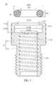
- FIG. 4 is a sectional view illustrating the tire pressure gauge of the present disclosure fastened to a French air valve.
- FIG. 5 is an exploded schematic view illustrating the connector assembly of the tire pressure gauge according to the present disclosure.
- FIG. 6 and FIG. 7 are sectional exploded views illustrating the connector assembly of the tire pressure gauge according to the present disclosure.
- FIG. 8 and FIG. 9 are sectional views illustrating the connector assembly of the tire pressure gauge according to the present disclosure.
- a tire pressure gauge 1 of the present disclosure can be directly fastened to a French air valve B 2 of a tire B 1 , in which the tire pressure gauge 1 can measure tire pressure anytime during the travel of the tire B 1 .
- the tire pressure gauge 1 of the present disclosure includes a connector assembly 10 and a gauge assembly 20 .
- the connector assembly 10 is fastened to the French air valve B 2 , as shown in FIG. 1 .
- the connector assembly 10 includes a main body 11 and an air-tight member 12 .
- a thread structure 11 s is formed on the circumference of an end portion of the main body 11 , and the gauge assembly 20 can be connected with the connector assembly 10 through the thread structure 11 s.
- the connection manner between the gauge assembly 20 and the connector assembly 10 can be connection manners other than the aforementioned screw connection.
- the gauge assembly 20 can include a wireless transmission unit and a processing unit, in which the processing unit can generate a tire pressure information according to the pressure of the air entering the gauge assembly 20 .
- the present disclosure is not limited by the way the processing unit measures air pressure and generates the tire pressure information.
- the wireless transmission unit is electrically connected to the processing unit and an external communication device D, which can be exemplified as a smartphone (as shown in FIG. 1B ) or a recorder so as to transmit the tire pressure information to the external communication device D. In this way, a bicycle rider can obtain the tire pressure information at any time during riding through the external communication device D.
- the gauge assembly 20 can further include a speed measurement unit (not shown in the drawings) electrically connected to the processing unit, which receives speed information measured by the speed measurement unit and transmits the speed information to the external communication device D through the wireless transmission unit.
- the processing unit can generate pedaling frequency information and power information calculated based on the tire pressure information and the speed information.
- the connector assembly 10 includes a main body 11 and an air-tight member 12 .
- the main body 11 includes a front member 111 and a connecting member 112 , in which the front member 111 has a connection end 111 a and an extension end 111 b.
- the front member 111 is connected to the French air valve B 2 at the connection end 111 a, and the connecting member 112 is connected to the front member 111 through the extension end 111 b.
- the front member 111 includes an opening portion 1111 at the connection end 111 a that extends inwards.
- the front member 111 further includes a first thread hole 1112 at the extension end 111 b that extends inwards.
- the first thread hole 1112 is used for being connected to a part of the French air valve B 2 . That is to say, a thread structure is formed on the inner surface of the first thread hole 1112 that corresponds to the French air valve B 2 .
- An accommodating channel 1113 is formed between the opening portion 1111 and the first thread hole 1112 .
- the opening portion 1111 , the first thread hole 1112 , and the accommodating channel 1113 are coaxial and communicate with each other.
- the inner diameter 1111 D of the opening portion 1111 is smaller than the inner diameter 1113 D of the accommodating channel 1113
- the inner diameter 1112 D of the first thread hole 1112 is smaller than the inner diameter 1111 D of the opening portion 1111 .
- the opening portion 1111 , the first thread hole 1112 , and the accommodating channel 1113 are hollow cylindrical bodies.
- a second thread hole 1121 is formed inside the connecting member 112 , and is coaxial with the first thread hole 1112 . Furthermore, the second thread hole 1121 communicates with the first thread hole 1112 and has an inner diameter the same as that of the first thread hole 1112 .
- FIG. 4 When the connector assembly 10 is fastened to the French air valve B 2 , a part of the French air valve B 2 is engaged with the first thread hole 1112 and the second thread hole 1121 . In other words, a continual thread structure is formed on the first thread hole 1112 and the second thread hole 1121 to be connected with the French air valve B 2 .
- the outer diameter of the connecting member 112 is smaller than that of the front member 111 , and the axial length of the connecting member 112 is greater than that of the front member 111 .
- the front member 111 and the connecting member 112 are integrally made of a titanium alloy, which can reduce the possibility of screw slippage due to abraded thread structure of the first thread hole 1112 and the second thread hole 1121 .
- a main body 11 made of a titanium alloy is harder to manufacture than a main body 11 made of an aluminum alloy or a copper alloy is; however, the former would have a relatively strong structure, which can thus prevent screw slippage.
- the tire pressure gauge 1 of the present disclosure is fastened to the tire B 1 and the connector assembly 10 is exposed to external environment, the connector assembly 10 is susceptible to damage such as rust caused by rain, air, etc. Therefore, the use of titanium alloy can prevent the connector assembly 10 from the aforementioned damage.
- the air-tight member 12 is annular and made of an abrasion-resistant material.
- the air-tight member 12 can be disposed in the accommodating channel 1113 by passing through the opening portion 1111 .
- the cross section of the air-tight member 12 can be a circle, which can achieve a higher effect of airproofing.
- the outer diameter 12 OD of the air-tight member 12 is smaller than the inner diameter 1113 D of the accommodating channel 1113
- the thickness 12 H of the air-tight member 12 is smaller than the axial depth 1113 H of the accommodating channel 1113 . That is to say, with reference to FIG.
- the inner diameter 12 ID of the air-tight member 12 is smaller than that of the second thread hole 1121 . Therefore, with reference to FIG. 4 , when the French air valve B 2 is engaged with the first thread hole 1112 and the second thread hole 1121 , the circumference of the air-tight member 12 is squeezed by the inner surface of the accommodating channel 1113 , and the inner surface of the air-tight member 12 is squeezed by the French air valve B 2 . When the air-tight member 12 deforms due to the press from the French air valve B 2 , the gap G vanishes.
- a gap G exists between the air-tight member 12 and the inner surface of the accommodating channel 1113 in the axial direction, and when the connector assembly 10 is fastened to the French air valve B 2 , the inner surface of the air-tight member 12 is squeezed by the French air valve B 2 so that the air-tight member 12 deforms to fill the gap G.
- the air-tight member 12 can securely adhere to the French air valve B 2 and the inner surface of the accommodating channel 1113 .
- the Shore hardness of the air-tight member 12 is no less than 65, and the difference between the outer diameter 12 OD of the air-tight member 12 and the inner diameter 1113 D of the accommodating channel 1113 is 0.5 mm. Furthermore, the difference between the thickness 12 H of the air-tight member 12 and the axial depth 1113 H of the accommodating channel 1113 is 0.2 mm, and the difference between the inner diameter 121 D of the air-tight member 12 and the outer diameter of the French air valve B 2 is 0.3 mm to 0.5 mm.
- the air-tight member 12 when the air-tight member 12 is disposed in the accommodating channel 1113 and the connector assembly is engaged with the French air valve B 2 , the air-tight member 12 can be in tight contact with the inner surface of the accommodating channel 1113 and the circumference of the French air valve B 2 .
- the inner diameter 1111 D of the opening portion 1111 ranges from 6.2 mm to 6.3 mm, and the inner diameter 1113 D of the accommodating channel 1113 is 1.2 to 1.3 times larger than the inner diameter 1111 D of the opening portion 1111 . Furthermore, the inner diameter 1111 D of the opening portion 1111 is 1.3 times larger than that of the first thread hole 1112 , and the axial depth 1111 H of the opening portion 1111 is 4 to 5 times larger than that of the accommodating channel 1113 .
- the air-tight member 12 can pass through the opening portion 1111 to be disposed in the accommodating channel 1113 ; furthermore, with the designed inner diameter and axial depth of the opening portion 1111 together with the design that the air-tight member 12 can be squeezed by the inner surface of the accommodating channel 1113 , when the connector assembly 10 is not connected to the French air valve B 2 , the air-tight member 12 is not thrown out from the opening portion 1111 due to the high pressure (100 psi) inside the tire and the French air valve B 2 .
- the connector assembly and the gauge assembly can engage each other so that the tire pressure gauge of the present disclosure can be fastened to the French air valve on the tire of a bicycle. Moreover, the bicycle rider can retrieve tire pressure information through an external communication device so as to track the tire status at any time.
- the connector assembly is made of a titanium alloy so that screw slippage due to abraded thread structure on both the connector assembly and the French air valve can be avoided. Furthermore, the connector assembly being made of titanium alloy can prevent damage such as rust caused by the exposure to external environment.
- the gas-tight member can achieve the effect of airproofing when engaged with the connector assembly and the French air valve, and can further prevent the gas-tight member from being thrown out of the connector assembly when the connector assembly and the French air vale are not engaged with each other.
Landscapes
- Engineering & Computer Science (AREA)
- Mechanical Engineering (AREA)
- Measuring Fluid Pressure (AREA)
Abstract
Description
Claims (10)
Priority Applications (1)
| Application Number | Priority Date | Filing Date | Title |
|---|---|---|---|
| US15/618,192 US10245907B2 (en) | 2017-06-09 | 2017-06-09 | Tire pressure gauge for bicycle |
Applications Claiming Priority (1)
| Application Number | Priority Date | Filing Date | Title |
|---|---|---|---|
| US15/618,192 US10245907B2 (en) | 2017-06-09 | 2017-06-09 | Tire pressure gauge for bicycle |
Publications (2)
| Publication Number | Publication Date |
|---|---|
| US20180354318A1 US20180354318A1 (en) | 2018-12-13 |
| US10245907B2 true US10245907B2 (en) | 2019-04-02 |
Family
ID=64562484
Family Applications (1)
| Application Number | Title | Priority Date | Filing Date |
|---|---|---|---|
| US15/618,192 Expired - Fee Related US10245907B2 (en) | 2017-06-09 | 2017-06-09 | Tire pressure gauge for bicycle |
Country Status (1)
| Country | Link |
|---|---|
| US (1) | US10245907B2 (en) |
Families Citing this family (3)
| Publication number | Priority date | Publication date | Assignee | Title |
|---|---|---|---|---|
| USD974204S1 (en) * | 2019-09-12 | 2023-01-03 | Suzhou Sate Auto Electronic Co., Ltd. | Wall-mounted tire pressure monitoring sensor |
| USD1057579S1 (en) * | 2023-10-23 | 2025-01-14 | Zhuji Danbo Tools Co., Ltd. | Air chuck |
| USD1066086S1 (en) * | 2023-10-23 | 2025-03-11 | Zhuji Danbo Tools Co., Ltd. | Air chuck |
Citations (3)
| Publication number | Priority date | Publication date | Assignee | Title |
|---|---|---|---|---|
| US9387732B1 (en) * | 2009-08-05 | 2016-07-12 | Honda Motor Co., Ltd. | Tire pressure monitoring system (TPMS) activation method |
| US20170197112A1 (en) * | 2016-01-08 | 2017-07-13 | National Taiwan Normal University | Dynamic tire pressure sensor system for a bike |
| US10124635B1 (en) * | 2017-07-18 | 2018-11-13 | Shu-Chun Hsiao | Bicycle tire pressure cap |
-
2017
- 2017-06-09 US US15/618,192 patent/US10245907B2/en not_active Expired - Fee Related
Patent Citations (3)
| Publication number | Priority date | Publication date | Assignee | Title |
|---|---|---|---|---|
| US9387732B1 (en) * | 2009-08-05 | 2016-07-12 | Honda Motor Co., Ltd. | Tire pressure monitoring system (TPMS) activation method |
| US20170197112A1 (en) * | 2016-01-08 | 2017-07-13 | National Taiwan Normal University | Dynamic tire pressure sensor system for a bike |
| US10124635B1 (en) * | 2017-07-18 | 2018-11-13 | Shu-Chun Hsiao | Bicycle tire pressure cap |
Also Published As
| Publication number | Publication date |
|---|---|
| US20180354318A1 (en) | 2018-12-13 |
Similar Documents
| Publication | Publication Date | Title |
|---|---|---|
| US10245907B2 (en) | Tire pressure gauge for bicycle | |
| JP2013170884A (en) | Fluid measuring sensor mounting structure | |
| US9027397B2 (en) | Tire pressure sensor applicable to different wheel rims | |
| US20130009762A1 (en) | Tire pressure sensor and nozzle assembly | |
| JP4741444B2 (en) | Tire valve unit | |
| US9884526B2 (en) | Electronic unit for measuring working parameters of a vehicle wheel | |
| US20210122439A1 (en) | Noncircular steerer tube and coupler | |
| JP6530605B2 (en) | Tire pressure sensor | |
| US20130333459A1 (en) | Valve stem for a wireless tire pressure detector | |
| US9664314B2 (en) | Valve connector for a valve of an inflating device and adapter having the same | |
| US11738825B2 (en) | Power pedal | |
| US7621177B2 (en) | Attached tire pressure sensor and air nozzle assembly | |
| CN203616040U (en) | Piezoresistive sensor with metal flow sealing structure | |
| CN202038125U (en) | Angle-adjustable tyre pressure transmitter | |
| CN204123910U (en) | Clamp-in valve | |
| EP3511181B1 (en) | Bicycle and tire structure | |
| US11173742B2 (en) | Clear hubcaps with oil range markings | |
| CN203472436U (en) | Tire pressure monitoring transmitter device | |
| US20100171361A1 (en) | Tyre Valve | |
| US20130200614A1 (en) | Device for pivotably connecting hydraulic line to hydraulic brake of bicycle | |
| CN104271369A (en) | Valve unit for filling the wheels | |
| CN204605422U (en) | Tire pressure monitoring sensor | |
| JPWO2018003021A1 (en) | Holding structure for tire pressure detecting device | |
| TWM467568U (en) | Tire pressure monitor suitable for different rims | |
| US20210170815A1 (en) | Inflation valve for tyre rim with limitation of elastic deformation |
Legal Events
| Date | Code | Title | Description |
|---|---|---|---|
| AS | Assignment |
Owner name: AUDEN TECHNO CORP., TAIWAN Free format text: ASSIGNMENT OF ASSIGNORS INTEREST;ASSIGNOR:LIN, TSAN-CHEN;REEL/FRAME:042679/0023 Effective date: 20170606 |
|
| STCF | Information on status: patent grant |
Free format text: PATENTED CASE |
|
| AS | Assignment |
Owner name: TBS GROUP CORPORATION, TAIWAN Free format text: ASSIGNMENT OF ASSIGNORS INTEREST;ASSIGNOR:AUDEN TECHNO CORP.;REEL/FRAME:059212/0933 Effective date: 20220301 Owner name: AUDEN TECHNO CORP., TAIWAN Free format text: ASSIGNMENT OF ASSIGNORS INTEREST;ASSIGNOR:AUDEN TECHNO CORP.;REEL/FRAME:059212/0933 Effective date: 20220301 |
|
| FEPP | Fee payment procedure |
Free format text: MAINTENANCE FEE REMINDER MAILED (ORIGINAL EVENT CODE: REM.); ENTITY STATUS OF PATENT OWNER: SMALL ENTITY |
|
| LAPS | Lapse for failure to pay maintenance fees |
Free format text: PATENT EXPIRED FOR FAILURE TO PAY MAINTENANCE FEES (ORIGINAL EVENT CODE: EXP.); ENTITY STATUS OF PATENT OWNER: SMALL ENTITY |
|
| STCH | Information on status: patent discontinuation |
Free format text: PATENT EXPIRED DUE TO NONPAYMENT OF MAINTENANCE FEES UNDER 37 CFR 1.362 |
|
| FP | Lapsed due to failure to pay maintenance fee |
Effective date: 20230402 |