US10240820B2 - Clamp for securing and electrically bonding solar panels to a rail support - Google Patents
Clamp for securing and electrically bonding solar panels to a rail support Download PDFInfo
- Publication number
- US10240820B2 US10240820B2 US15/081,369 US201615081369A US10240820B2 US 10240820 B2 US10240820 B2 US 10240820B2 US 201615081369 A US201615081369 A US 201615081369A US 10240820 B2 US10240820 B2 US 10240820B2
- Authority
- US
- United States
- Prior art keywords
- clamp
- solar panel
- jaw
- panel module
- rail support
- Prior art date
- Legal status (The legal status is an assumption and is not a legal conclusion. Google has not performed a legal analysis and makes no representation as to the accuracy of the status listed.)
- Active
Links
Images


Classifications
-
- F—MECHANICAL ENGINEERING; LIGHTING; HEATING; WEAPONS; BLASTING
- F24—HEATING; RANGES; VENTILATING
- F24S—SOLAR HEAT COLLECTORS; SOLAR HEAT SYSTEMS
- F24S25/00—Arrangement of stationary mountings or supports for solar heat collector modules
- F24S25/60—Fixation means, e.g. fasteners, specially adapted for supporting solar heat collector modules
- F24S25/63—Fixation means, e.g. fasteners, specially adapted for supporting solar heat collector modules for fixing modules or their peripheral frames to supporting elements
- F24S25/634—Clamps; Clips
- F24S25/636—Clamps; Clips clamping by screw-threaded elements
-
- F—MECHANICAL ENGINEERING; LIGHTING; HEATING; WEAPONS; BLASTING
- F24—HEATING; RANGES; VENTILATING
- F24S—SOLAR HEAT COLLECTORS; SOLAR HEAT SYSTEMS
- F24S25/00—Arrangement of stationary mountings or supports for solar heat collector modules
- F24S25/30—Arrangement of stationary mountings or supports for solar heat collector modules using elongate rigid mounting elements extending substantially along the supporting surface, e.g. for covering buildings with solar heat collectors
-
- F—MECHANICAL ENGINEERING; LIGHTING; HEATING; WEAPONS; BLASTING
- F24—HEATING; RANGES; VENTILATING
- F24S—SOLAR HEAT COLLECTORS; SOLAR HEAT SYSTEMS
- F24S25/00—Arrangement of stationary mountings or supports for solar heat collector modules
- F24S25/60—Fixation means, e.g. fasteners, specially adapted for supporting solar heat collector modules
- F24S25/63—Fixation means, e.g. fasteners, specially adapted for supporting solar heat collector modules for fixing modules or their peripheral frames to supporting elements
- F24S25/632—Side connectors; Base connectors
-
- F—MECHANICAL ENGINEERING; LIGHTING; HEATING; WEAPONS; BLASTING
- F24—HEATING; RANGES; VENTILATING
- F24S—SOLAR HEAT COLLECTORS; SOLAR HEAT SYSTEMS
- F24S25/00—Arrangement of stationary mountings or supports for solar heat collector modules
- F24S25/60—Fixation means, e.g. fasteners, specially adapted for supporting solar heat collector modules
- F24S25/63—Fixation means, e.g. fasteners, specially adapted for supporting solar heat collector modules for fixing modules or their peripheral frames to supporting elements
- F24S25/634—Clamps; Clips
-
- H—ELECTRICITY
- H02—GENERATION; CONVERSION OR DISTRIBUTION OF ELECTRIC POWER
- H02S—GENERATION OF ELECTRIC POWER BY CONVERSION OF INFRARED RADIATION, VISIBLE LIGHT OR ULTRAVIOLET LIGHT, e.g. USING PHOTOVOLTAIC [PV] MODULES
- H02S20/00—Supporting structures for PV modules
- H02S20/20—Supporting structures directly fixed to an immovable object
- H02S20/22—Supporting structures directly fixed to an immovable object specially adapted for buildings
- H02S20/23—Supporting structures directly fixed to an immovable object specially adapted for buildings specially adapted for roof structures
-
- F—MECHANICAL ENGINEERING; LIGHTING; HEATING; WEAPONS; BLASTING
- F24—HEATING; RANGES; VENTILATING
- F24S—SOLAR HEAT COLLECTORS; SOLAR HEAT SYSTEMS
- F24S25/00—Arrangement of stationary mountings or supports for solar heat collector modules
- F24S25/60—Fixation means, e.g. fasteners, specially adapted for supporting solar heat collector modules
- F24S2025/6008—Fixation means, e.g. fasteners, specially adapted for supporting solar heat collector modules by using toothed elements
-
- F—MECHANICAL ENGINEERING; LIGHTING; HEATING; WEAPONS; BLASTING
- F24—HEATING; RANGES; VENTILATING
- F24S—SOLAR HEAT COLLECTORS; SOLAR HEAT SYSTEMS
- F24S25/00—Arrangement of stationary mountings or supports for solar heat collector modules
- F24S2025/80—Special profiles
- F24S2025/801—Special profiles having hollow parts with closed cross-section
-
- F—MECHANICAL ENGINEERING; LIGHTING; HEATING; WEAPONS; BLASTING
- F24—HEATING; RANGES; VENTILATING
- F24S—SOLAR HEAT COLLECTORS; SOLAR HEAT SYSTEMS
- F24S25/00—Arrangement of stationary mountings or supports for solar heat collector modules
- F24S2025/80—Special profiles
- F24S2025/807—Special profiles having undercut grooves
-
- Y—GENERAL TAGGING OF NEW TECHNOLOGICAL DEVELOPMENTS; GENERAL TAGGING OF CROSS-SECTIONAL TECHNOLOGIES SPANNING OVER SEVERAL SECTIONS OF THE IPC; TECHNICAL SUBJECTS COVERED BY FORMER USPC CROSS-REFERENCE ART COLLECTIONS [XRACs] AND DIGESTS
- Y02—TECHNOLOGIES OR APPLICATIONS FOR MITIGATION OR ADAPTATION AGAINST CLIMATE CHANGE
- Y02B—CLIMATE CHANGE MITIGATION TECHNOLOGIES RELATED TO BUILDINGS, e.g. HOUSING, HOUSE APPLIANCES OR RELATED END-USER APPLICATIONS
- Y02B10/00—Integration of renewable energy sources in buildings
- Y02B10/10—Photovoltaic [PV]
-
- Y02B10/12—
-
- Y—GENERAL TAGGING OF NEW TECHNOLOGICAL DEVELOPMENTS; GENERAL TAGGING OF CROSS-SECTIONAL TECHNOLOGIES SPANNING OVER SEVERAL SECTIONS OF THE IPC; TECHNICAL SUBJECTS COVERED BY FORMER USPC CROSS-REFERENCE ART COLLECTIONS [XRACs] AND DIGESTS
- Y02—TECHNOLOGIES OR APPLICATIONS FOR MITIGATION OR ADAPTATION AGAINST CLIMATE CHANGE
- Y02B—CLIMATE CHANGE MITIGATION TECHNOLOGIES RELATED TO BUILDINGS, e.g. HOUSING, HOUSE APPLIANCES OR RELATED END-USER APPLICATIONS
- Y02B10/00—Integration of renewable energy sources in buildings
- Y02B10/20—Solar thermal
-
- Y—GENERAL TAGGING OF NEW TECHNOLOGICAL DEVELOPMENTS; GENERAL TAGGING OF CROSS-SECTIONAL TECHNOLOGIES SPANNING OVER SEVERAL SECTIONS OF THE IPC; TECHNICAL SUBJECTS COVERED BY FORMER USPC CROSS-REFERENCE ART COLLECTIONS [XRACs] AND DIGESTS
- Y02—TECHNOLOGIES OR APPLICATIONS FOR MITIGATION OR ADAPTATION AGAINST CLIMATE CHANGE
- Y02E—REDUCTION OF GREENHOUSE GAS [GHG] EMISSIONS, RELATED TO ENERGY GENERATION, TRANSMISSION OR DISTRIBUTION
- Y02E10/00—Energy generation through renewable energy sources
- Y02E10/40—Solar thermal energy, e.g. solar towers
- Y02E10/47—Mountings or tracking
-
- Y—GENERAL TAGGING OF NEW TECHNOLOGICAL DEVELOPMENTS; GENERAL TAGGING OF CROSS-SECTIONAL TECHNOLOGIES SPANNING OVER SEVERAL SECTIONS OF THE IPC; TECHNICAL SUBJECTS COVERED BY FORMER USPC CROSS-REFERENCE ART COLLECTIONS [XRACs] AND DIGESTS
- Y02—TECHNOLOGIES OR APPLICATIONS FOR MITIGATION OR ADAPTATION AGAINST CLIMATE CHANGE
- Y02E—REDUCTION OF GREENHOUSE GAS [GHG] EMISSIONS, RELATED TO ENERGY GENERATION, TRANSMISSION OR DISTRIBUTION
- Y02E10/00—Energy generation through renewable energy sources
- Y02E10/50—Photovoltaic [PV] energy
Definitions
- the present invention relates generally to providing an apparatus for securing a solar panel module to a rail support structure. More specifically, the invention relates to the use of an end clamp that mounts a bottom flange of a solar panel module to a rail support structure without requiring any tools for installation, while also mechanically fastening and electrically bonding the solar panel module to the rail support structure.
- Solar panel arrays can be installed using different rail support structures.
- One type of rail support structure utilizes a series of rails that are arranged in rows across a roof and fixed to flashings that are secured to the roof. The solar panels are then arranged in an array and secured to the top of these rails.
- One type of rail support structure includes slots or guides along the top of the rail for receiving mid-clamps or similar mounting hardware used to couple and secure two solar panels to the rails.
- One reason mid-clamps are advantageous for securing the solar panels to the rails within the interior of the array is that they can secure multiple panels at the same time. This is normally accomplished by inserting an elongated bolt in the rail guide, placing a pair of the solar panels alongside the bolt and joining the panels by tightening a clamp plate to the bolt on top of the panels at the other end of the rail guide.
- a limitation of these types of mid-clamps is that they are exposed on top of the panels and can be aesthetically unsightly if used along the perimeter of the array.
- clamp that not only secures the solar panels to the rails outer perimeter of the array, but is also easy to install, electrically grounds the solar panel to the rail guides, and is hidden from plain sight of the array thereby making the outer perimeter of the solar panel array more visibly appealing.
- clamp and “end clamp” are used interchangeably as it applies to the present invention.
- U.S. Pat. No. 8,590,223 teaches a solar panel assembly attachment apparatus that utilizes a single piece clip that fits linearly within a rail guide and is used to secure a solar panel module to a rail.
- the device also includes a grounding clip having a barb that attaches to a flange on the solar panel module to ground the module to the rail.
- this device is secured to the rail guide by utilizing one or more flexible wings that are removably snap-fit into a slot of an elongated and rigid strut. This makes the manufacture and installation of this device more complex than the present invention.
- German patent DE 20-2011108873 Another example of a clamp that is used to secure a solar panel module to support rails with guides or slots located on the top of the rail structures is German patent DE 20-2011108873.
- This patent teaches an end clamp that is inserted within a rail guide as shown in FIG. 2B.
- One end of the clamp secures a bottom flange of a solar panel to the rail, while the other end is secured outside of the perimeter of the solar panel array by way of a clamping screw.
- this device does not include unidirectional barbs that act as both grounding features and securing mechanisms that prevent the clamp from coming off the flange of the solar panel once engaged with it.
- the present invention overcomes the limitations in both of these pieces of prior art and provides a solution that is both easy to, install, use, and manufacture.
- clamp fit within, and move bi-directionally along a rail guide of the rail support structure.
- the clamp is a generally u-shaped body.
- the u-shaped body includes a top and bottom jaw connected to opposite ends of a rear end.
- top and bottom jaws of the clamp can receive a flange of the solar panel module within the clamp.
- the top jaw of the clamp has at least one raised portion for coupling and electrically bonding to the top surface of the flange of the solar panel module by having the raised portion penetrate an oxidation layer of the flange.
- the bottom jaw is configured to fit within, and move bi-directionally along a guide of the rail support structure and couple and electrically bond to the rail support structure by penetrating an oxidation layer of the rail support structure.
- the rear end of the clamp provides sufficient resilience to enable the top and bottom jaws of the clamp to secure the flange to the rail support by gripping the upper and lower surfaces of the flange.
- the at least one raised portion tapers toward the rear end of the clamp at an acute angle with respect to the top jaw.
- the bottom jaw is elongated and includes an aperture at the end of the bottom jaw.
- any shape or size of the elements described below may be adopted as long as the end clamp can be used to secure solar panel modules to the rail support structures and provide a grounding path from the modules to the rail support structures. Any combinations of suitable number, shape, and size of the elements described below may be used. Also, any materials suitable to achieve the object of the current invention may be chosen as well.
- FIG. 1 illustrates a rear perspective view of an exemplary clamp.
- FIG. 2 illustrates a front perspective view of the clamp.
- FIG. 3 illustrates a perspective view of the clamp inserted into a guide of a rail support structure.
- FIG. 4 illustrates a perspective view of the clamp secured between a flange of a solar panel module and the guide of the rail support structure.
- FIG. 7 illustrates an exploded view of the clamp as it moves toward the guide of the rail support structure.
- FIG. 8 is a reverse perspective view of FIG. 3 .
- FIG. 11 illustrates a side view of the clamp as it moves toward the guide of the rail support structure.
- FIG. 12 illustrates side view of the clamp secured to the solar panel module.
- FIG. 5 illustrates a cross sectional view of the clamp securing the flange of the solar panel module to the guide of the rail support structure.
- FIG. 6 illustrates cross-sectional view of the clamp along points 6 - 6 as shown in FIG. 5 .
- FIG. 9 illustrates the perspective view of FIG. 3 showing a solar panel module prior to placing it on top of the rail support structure.
- FIG. 10 illustrates the same view of FIG. 9 showing the clamp fully engaged with the lower flange of the solar panel module.
- FIG. 13 illustrates a perspective view of a completed assembly of a solar panel module to a pair of rail support structures.
- FIG. 14 illustrates a side view showing the raised portions on the clamp penetrating the surface of the bottom flange of the solar panel module and securing it to the guide.
- FIG. 15 illustrates a solar panel module positioned over two rail structures.
- FIG. 16 illustrates an exploded view of an alternate embodiment of the end clamp with an elongated lower portion.
- FIG. 16A illustrates a side view of the clamp.
- FIG. 16B illustrates a top view of the clamp.
- FIG. 16C illustrates a bottom view of the clamp.
- FIG. 17 illustrates a perspective view of the elongated clamp as it moves toward the guide of the rail support structure.
- FIG. 18 illustrates a perspective view of the elongated clamp installed on the guide of the rail support structure.
- FIG. 19 illustrates the perspective view of FIG. 18 showing a solar panel module prior to placing it on top of the elongated end clamp.
- FIG. 20 illustrates the same view of FIG. 19 showing the clamp fully engaged with the lower flange of the solar panel module.
- FIG. 21 Illustrates a side view of FIG. 20 .
- FIG. 22 illustrates the same view as FIG. 21 showing the nut on the t-bolt being tightened.
- FIG. 23 illustrates a cross-sectional view of FIG. 21 .
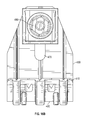
- FIG. 24 illustrates a perspective view of a completed assembly.
- FIG. 25 illustrates a side view of the clamp with the solar panel module inserted into the clamp.
- FIG. 26 illustrates a cross-sectional view of ( 26 - 26 ) from FIG. 25 .
- FIGS. 1 and 2 show two perspective views of an end clamp 100 for use in fastening a solar panel module to a rail support structure 200 (as shown in FIGS. 3 and 4 ).
- the exemplary embodiment of the end clamp 100 is generally a c-shaped or u-shaped structure that includes a top jaw 110 , a rear end 120 , and a bottom jaw 130 .
- the top and bottom jaws 110 and 130 are typically in the form of flanges, but can be of any suitable shape that forms a mouth-like opening with respect to the rear end 120 .
- the end clamp 100 is typically made from an electrically conducting material.
- a pair of bottom side flanges 135 are also included and are positioned on opposite sides of the bottom jaw 130 .
- the bottom side flanges 135 provide added stability and gripping area of the flange 310 as discussed below.
- the rear end 120 is slightly flexible so that it allows a limited amount of angular movement of the top and bottom jaws 110 and 130 when they are pulled outward or recoil inward.
- a pair of apertures 140 are positioned between the two bottom side flanges 135 .
- the apertures 140 extend from the terminal ends of the bottom side flanges 135 to rear portions 115 of the top jaw 110 .
- Bottom jaw 130 includes at least one sharp edge 136 configured to penetrate an oxidation layer of the rail support structure 200 . In this embodiment, two sharp edges 136 are shown on opposite sides of the bottom jaw 130 to provide multiple engagement points with the rail support structure 200 .
- FIG. 2 shows the front of the end clamp 100 .
- the top jaw 110 includes raised portions 150 that protrude downward. A plurality of raised portions 150 is desired, but one raised portion 150 may be sufficient.
- the raised portion 150 preferably tapers to a sharp point 155 .
- the raised portions 150 are directed toward the rear end 120 of the end clamp 100 so that the point 155 is at an acute angle with respect to the top jaw 110 .
- FIGS. 3 and 4 show a typical configuration with a rail support structure 200 and a solar panel module 300 that includes a flange 310 on its lower end.
- the rail support 200 is normally secured to a flashing structure that has been previously installed on a roof (not shown) and includes a guide 210 on or near the top of the support 200 for receiving the end clamp 100 .
- the process of securing the solar panel module 300 to the rail support 200 is accomplished by inserting the bottom jaw 130 of the end clamp 100 into an open end 225 of the guide 210 and enabling the apertures 140 to follow the contour of the upper and side walls 220 of the guide 210 as shown in FIGS. 5 and 6 .
- the bottom side flanges 135 flank the outer portions of the side walls 220 as the end clamp 100 is inserted into the guide 210 .
- An exemplary bottom jaw 130 will frictionally engage the inner walls 230 of the guide 210 while allowing the end clamp 100 to move bi-directionally along the guide 210 . All of this can normally be accomplished without the use of any tools.
- the solar panel module 300 is placed on top of the rail support 200 so that the lower flange 310 is substantially perpendicular to the guide 210 .
- the end clamp 100 is then manually pushed along the guide 210 toward the lower flange 310 of the solar panel module 300 .
- the space between the top jaw 110 and bottom jaw 130 is sufficient to allow the bidirectional movement to occur along the guide 210 .
- the end clamp 100 forms a tight grip of the lower flange 310 as the top jaw 110 of the end clamp 100 engages the top surface of the lower flange 310 , and the bottom jaw 130 engages the bottom surface of the lower jaw 130 .
- the rear end 120 provides sufficient resiliency to enable the top jaw 110 and lower jaw 13 to provide an adequate gripping force to compress the lower flange 310 to the guide 210 .
- the points 155 of the raised portions 150 are then deflected slightly upward toward the top jaw 110 and form a tight grip on the top surface of the lower flange 310 .
- the slight deflection allows the end clamp 100 to continue to move along the guide 210 toward the solar panel module 300 until the lower flange 310 reaches the rear end 120 of the end clamp 100 . As shown in FIGS.
- the sharp points 155 penetrate the outer surface layer of the lower flange 310
- the sharp edges 136 penetrate the outer surface layer of the side walls 220 and create a grounding path from the solar panel module 300 to the rail support 200 through the end clamp 100 .
- the combination of the rearward-pointing angle of the raised portions 150 with the tightness of the gripping force formed between the top jaw 110 and the bottom jaw 130 allow the points 155 to resist any attempt to pull the end clamp 100 away from the solar panel module 300 essentially locking the solar panel module 300 in place.
- the end clamp 100 can be unlocked and moved backward along the guide 210 by pulling the top jaw 110 and the bottom jaw 130 apart so that the raised portions 150 disengage from the lower flange 310 .
- FIG. 13 shows a perspective view of the clamp 100 fully engaged and securing the solar panel module 300 to the rail support 200 and providing an electrical conducting path between the them.
- FIG. 12 shows a view from the opposite side of the solar panel module 300 and
- FIG. 15 shows the solar panel module 300 as it rests on two distinct rail supports 200 demonstrating that the end clamp 100 is hidden from plain view. This process is repeated until all end clamps 100 are installed. After the first row is installed, each subsequent row is installed by repeating the process described above.
- FIG. 16 shows an exploded view of an alternate end clamp 400 .
- the end clamp 400 includes some of the same features as the end clamp 100 in terms of how it engages and secures the lower flange 310 on the solar panel module 300 . But in this embodiment, the end clamp 400 provides an additional means to secure the end clamp 100 to the rail support 200 .
- the end clamp 400 is also a generally c-shaped or u-shaped clamp that includes a top jaw 410 , a rear end 420 , and a bottom jaw 430 .
- the top and bottom jaws 410 and 430 are typically in the form of flanges, but can be of any suitable shape that forms a mouth-like opening with respect to the rear end 420 .
- the end clamp 400 is typically made from an electrically conducting material.
- the bottom jaw 430 is extended outward beyond the edge of the top jaw 410 and includes an aperture 470 for receiving a t-bolt 490 as shown in FIG. 15 to secure the end clamp 400 to the rail support 200 .
- the t-bolt 490 is typically an elongated threaded bolt with a rectangular-shaped head on one end and includes raised portions 495 on the head that are used to grip the inside of the guide 210 of the rail support 200 as will be discussed below.
- the aperture 470 is typically positioned in the middle of the bottom jaw 430 and allows for the t-bolt 490 to be inserted and secured in various locations along the center of the bottom jaw 430 .
- the t-bolt 490 is tightened using a nut 480 .
- An optional back support 460 is also included.
- An exemplary back support 460 is L-shaped and includes a vertical face 462 with ridges 465 and a horizontal face 467 with an aperture 468 for receiving the t-bolt 490 .
- FIG. 16A shows a side view of the end clamp 430 , which also includes the raised portions 450 of top jaw 410 that protrudes downward.
- the structure of the raised portions 450 is the same as those shown in FIG. 2 for the first embodiment of the clamp 100 .
- a plurality of raised portions 450 is desired, but one raised portion 450 is sufficient.
- the raised portions 450 preferably taper to a sharp point 455 . As shown, the raised portion 450 is directed toward the rear end 420 of the end clamp 400 so that the point 455 is at an acute angle with respect to the top jaw 410 .
- FIG. 16B shows a top view of the end clamp 400 showing the features as described above while FIG. 16C shows a bottom view of the end clamp 400 .
- the bottom view shows the entirety of the bottom jaw 430 with the aperture 470 and grooves 425 .
- the head 485 of the t-bolt 490 is shown having been inserted through the aperture 470 .
- FIG. 19 shows a typical configuration with a rail support structure 200 and a solar panel module 300 that includes a flange 310 on its lower end.
- the end clamp 400 is positioned in the guide 210 of the rail support 200 as shown in FIGS. 17 and 18 along the grooves 425 where it can move bi-directionally along the guide 210 .
- the process of securing the solar panel module 300 to the rail support 200 in this embodiment is accomplished by placing the solar panel module 300 on top of the bottom jaw 430 so that the lower flange 310 is generally perpendicular to the guide 210 as shown in FIG. 20 .
- FIG. 21 shows a side view of the configuration.
- the lower flange 310 of the solar panel module 300 is then inserted the through the mouth of the top jaw 410 and bottom jaw 430 of the end clamp 400 so that the end clamp 400 forms a tight grip of the lower flange 310 as the top jaw 410 of the end clamp 400 engages the top surface of the lower flange 310 , and the bottom jaw 430 engages the bottom surface of the lower jaw 430 .
- the vertical face 465 of the optional back support 460 engages the rear surface 350 of the solar panel module 300 providing further support of the module 300 .
- FIG. 23 shows a cross-sectional view ( 23 - 23 ) from FIG. 21 .
- the points 455 of the raised portions 450 are then deflected slightly upward and form a tight grip on the top surface of the lower flange 310 .
- the deflection allows the end clamp 400 to continue to move along toward the solar panel module 300 until the lower flange 310 engages the rear end 420 of the end clamp 400 .
- the sharp points 455 penetrate the outer surface layer of the lower flange 310 .
- the t-bolt 490 is inserted through the aperture 468 of the optional back support 460 and through the aperture 470 of the bottom jaw 430 into the guide 210 .
- the nut 480 is then placed on the threaded portion of the t-bolt 490 and turned clockwise so that the t-bolt 490 engages the inner walls of the guide 210 .
- the raised portions 492 on the outer edges of the t-bolt 490 cause the t-bolt 490 to stop rotating so that the nut 480 can continue to turn and tighten the bottom jaw 430 to the guide 210 of the rail support 200 as shown in FIG. 23 thereby creating an electrical conducting path from the solar panel module 300 to the rail support 200 through the end clamp 400 .
- FIG. 24 shows the solar panel module 300 as it rests on two distinct rail supports 200 After the first row is installed, each subsequent row is installed by repeating the process described above.
Landscapes
- Engineering & Computer Science (AREA)
- Chemical & Material Sciences (AREA)
- Life Sciences & Earth Sciences (AREA)
- Sustainable Development (AREA)
- Sustainable Energy (AREA)
- Thermal Sciences (AREA)
- Physics & Mathematics (AREA)
- Combustion & Propulsion (AREA)
- Mechanical Engineering (AREA)
- General Engineering & Computer Science (AREA)
- Architecture (AREA)
- Civil Engineering (AREA)
- Structural Engineering (AREA)
- Roof Covering Using Slabs Or Stiff Sheets (AREA)
Abstract
Description
Claims (6)
Priority Applications (1)
| Application Number | Priority Date | Filing Date | Title |
|---|---|---|---|
| US15/081,369 US10240820B2 (en) | 2015-03-25 | 2016-03-25 | Clamp for securing and electrically bonding solar panels to a rail support |
Applications Claiming Priority (2)
| Application Number | Priority Date | Filing Date | Title |
|---|---|---|---|
| US201562137903P | 2015-03-25 | 2015-03-25 | |
| US15/081,369 US10240820B2 (en) | 2015-03-25 | 2016-03-25 | Clamp for securing and electrically bonding solar panels to a rail support |
Publications (2)
| Publication Number | Publication Date |
|---|---|
| US20160282018A1 US20160282018A1 (en) | 2016-09-29 |
| US10240820B2 true US10240820B2 (en) | 2019-03-26 |
Family
ID=56975057
Family Applications (1)
| Application Number | Title | Priority Date | Filing Date |
|---|---|---|---|
| US15/081,369 Active US10240820B2 (en) | 2015-03-25 | 2016-03-25 | Clamp for securing and electrically bonding solar panels to a rail support |
Country Status (1)
| Country | Link |
|---|---|
| US (1) | US10240820B2 (en) |
Cited By (21)
| Publication number | Priority date | Publication date | Assignee | Title |
|---|---|---|---|---|
| WO2020076870A1 (en) | 2018-10-08 | 2020-04-16 | The Board Of Regents Of The University Of Oklahoma | System for mounting solar panels |
| US20200132227A1 (en) * | 2018-10-31 | 2020-04-30 | Taiwan Semiconductor Manufacturing Company Ltd. | System for reducing friction-induced wear of pipe |
| US20210363755A1 (en) * | 2016-10-31 | 2021-11-25 | Rmh Tech Llc | Metal panel electrical bonding clip |
| US11202616B2 (en) * | 2016-11-03 | 2021-12-21 | B-K Medical Aps | Probe cable support |
| US11739529B2 (en) | 2020-03-16 | 2023-08-29 | Rmh Tech Llc | Mounting device for a metal roof |
| US11774143B2 (en) | 2017-10-09 | 2023-10-03 | Rmh Tech Llc | Rail assembly with invertible side-mount adapter for direct and indirect mounting applications |
| US11788291B2 (en) | 2020-03-17 | 2023-10-17 | Rmh Tech Llc | Mounting device for controlling uplift of a metal roof |
| US11885139B2 (en) | 2011-02-25 | 2024-01-30 | Rmh Tech Llc | Mounting device for building surfaces having elongated mounting slot |
| WO2024059343A1 (en) * | 2022-09-16 | 2024-03-21 | Unirac Inc. | Solar module mount |
| US12003206B2 (en) | 2021-08-24 | 2024-06-04 | Ironridge, Inc. | Rail-based solar panel mounting system |
| US12018861B2 (en) | 2011-12-29 | 2024-06-25 | Rmh Tech Llc | Mounting device for nail strip panels |
| US12044443B2 (en) | 2016-07-29 | 2024-07-23 | Rmh Tech Llc | Trapezoidal rib mounting bracket with flexible legs |
| US20240280214A1 (en) * | 2023-02-22 | 2024-08-22 | Panelclaw, Inc. | Frame Enhancer |
| US12088241B2 (en) | 2020-09-14 | 2024-09-10 | Array Tech, Inc. | Spring clip for photovoltaic module mounting |
| US12199557B2 (en) | 2020-07-23 | 2025-01-14 | The Board Of Regents Of The University Of Oklahoma | Adaptor for spring-based PV module fastener |
| US12203496B2 (en) | 2020-07-09 | 2025-01-21 | Rmh Tech Llc | Mounting system, device, and method |
| US12231081B2 (en) | 2018-03-21 | 2025-02-18 | Rmh Tech Llc | PV module mounting assembly with clamp/standoff arrangement |
| US20250060050A1 (en) * | 2023-08-17 | 2025-02-20 | Channel Master, Llc | Cable/tubular clamp and system using the same |
| USD1075493S1 (en) | 2022-07-06 | 2025-05-20 | Rmh Tech Llc | Clamp for a photovoltaic module mounting assembly |
| US12320375B2 (en) | 2018-12-14 | 2025-06-03 | Rmh Tech Llc | Mounting device for nail strip panels |
| US12399083B2 (en) * | 2023-07-26 | 2025-08-26 | Taiwan Semiconductor Manufacturing Company, Ltd. | Buffer for holding a pipe |
Families Citing this family (20)
| Publication number | Priority date | Publication date | Assignee | Title |
|---|---|---|---|---|
| US10594250B2 (en) | 2015-08-03 | 2020-03-17 | Unirac Inc. | Hybrid solar panel mounting assembly |
| US9893677B1 (en) | 2017-07-06 | 2018-02-13 | Sunmodo Corporation | Bottom clamp for mounting solar panels to roofs |
| CN107888141B (en) * | 2017-12-26 | 2024-04-19 | 浙江双宇电子科技有限公司 | Buckle of solar frame |
| EP4145059A1 (en) * | 2018-01-17 | 2023-03-08 | PanelClaw, Inc. | Solar module mounting system |
| FR3079890B1 (en) * | 2018-04-04 | 2020-04-03 | A. Raymond Et Cie | FIXING CLIP FOR PHOTOVOLTAIC CHASSIS WITH INSERTION MOUNTING THEN SLIDING IN A SLOT OF A SUPPORT WALL |
| US10622935B1 (en) | 2019-04-06 | 2020-04-14 | Sunmodo Corporation | Rail-mounted bottom clamp for mounting solar panels to roofs and the like |
| US11848636B2 (en) | 2019-06-04 | 2023-12-19 | Pegasus Solar, Inc. | Skip rail system |
| US12292075B2 (en) | 2019-11-25 | 2025-05-06 | Pegasus Solar Inc | Twist-lock solar module clamp |
| US11377840B2 (en) | 2019-11-26 | 2022-07-05 | Pegasus Solar Inc. | One-piece bonding splice for rails |
| US11649986B2 (en) * | 2020-02-05 | 2023-05-16 | John Powers, III | Purlin construction and clip for flat panel roof structures |
| PL4095458T3 (en) * | 2020-02-14 | 2024-08-12 | Esdec B.V. | System and method for mounting a solar panel onto a substantially flat mounting surface |
| USD1004141S1 (en) | 2020-12-01 | 2023-11-07 | Pegasus Solar, Inc. | Rail |
| US11143436B1 (en) * | 2020-12-14 | 2021-10-12 | Pegasus Solar, Inc. | Hidden end clamp |
| US11990862B2 (en) | 2021-02-18 | 2024-05-21 | Pegasus Solar Inc. | Rail accessory mount |
| BR112023023083A2 (en) * | 2021-05-05 | 2024-01-30 | Shoals Tech Group Llc | RETENTION CLIP FOR SOLAR CABLES AND SYSTEMS FOR ASSEMBLY STRUCTURES |
| US12281750B2 (en) | 2022-01-14 | 2025-04-22 | Pegasus Solar Inc | Grip rail clamp |
| USD1067757S1 (en) * | 2022-03-15 | 2025-03-25 | Panelclaw, Inc. | Wire clip and cover assembly |
| US12158229B2 (en) | 2022-03-21 | 2024-12-03 | Shoals Technologies Group, Llc | Photovoltaic wire management clip |
| US11770097B1 (en) * | 2023-03-15 | 2023-09-26 | Sunmodo Corporation | Rail-attached bottom clamp for solar panels secured to roofs and building structures |
| US20250067290A1 (en) * | 2023-08-21 | 2025-02-27 | Nextracker Llc | Solar module washer clip |
Citations (53)
| Publication number | Priority date | Publication date | Assignee | Title |
|---|---|---|---|---|
| US2467604A (en) * | 1946-09-19 | 1949-04-19 | Tinnerman Products Inc | Fastening construction |
| US2565636A (en) * | 1946-11-08 | 1951-08-28 | Tinnerman Products Inc | Spring latching fastener |
| US3122604A (en) * | 1958-11-12 | 1964-02-25 | Steel City Electric Company | Ground clip for electrical outlet and switch boxes |
| US3528050A (en) * | 1969-05-02 | 1970-09-08 | Holub Ind Inc | Push-on type grounding clip |
| US3536281A (en) * | 1968-01-04 | 1970-10-27 | Illinois Tool Works | Bracket structure |
| US3606223A (en) * | 1969-03-21 | 1971-09-20 | Spring Steel Fasteners Inc | Outlet box mounting clip |
| US3720395A (en) * | 1971-08-18 | 1973-03-13 | Fastway Fasteners | Clip for securing conduit boxes to metal dry wall studs |
| US3780209A (en) * | 1972-09-27 | 1973-12-18 | Fastway Fasteners | Clip for securing conduit boxes to metal dry wall studs |
| US3810069A (en) * | 1972-08-08 | 1974-05-07 | Hubbell Inc Harvey | Grounding clip for electrical fixtures |
| US4406505A (en) * | 1981-02-18 | 1983-09-27 | Daniel Woodhead, Inc. | Grounding clip for electrical fixtures |
| US4571013A (en) * | 1983-09-30 | 1986-02-18 | Northern Telecom Limited | Connector for cable shields |
| US4875876A (en) * | 1988-08-31 | 1989-10-24 | Thomas & Betts Corporation | Electrical connector for overlapped conductors |
| US4993959A (en) * | 1990-01-19 | 1991-02-19 | Amp Incorporated | Grounding clip |
| EP0508977A1 (en) * | 1991-04-09 | 1992-10-14 | ISOVOLTAÖsterreichische IsolierstoffwerkeAktiengesellschaft | Clip to connect two plate-like elements |
| US5451167A (en) * | 1994-07-28 | 1995-09-19 | Illinois Tool Works Inc. | Grounding clip |
| JPH0972057A (en) * | 1995-09-04 | 1997-03-18 | Nishikawa Rubber Co Ltd | Glass support member for heat collector |
| US6106310A (en) * | 1997-11-19 | 2000-08-22 | The Whitaker Corporation | Panel-grounding contact |
| US6389658B1 (en) * | 1999-05-05 | 2002-05-21 | Thomas & Betts International, Inc. | Clip for mounting objects on a wall stud |
| US6948687B2 (en) * | 2003-04-30 | 2005-09-27 | Heliocol Usa, Inc. | Clamp for holding solar collectors on roofs |
| US7686625B1 (en) * | 2008-11-07 | 2010-03-30 | Tyco Electronics Corporation | Grounding clip |
| DE202010007139U1 (en) | 2010-05-26 | 2010-09-02 | Green Factory Gmbh | Device for fixing a module for the use of solar energy |
| US20100276558A1 (en) * | 2009-05-01 | 2010-11-04 | Applied Energy Technologies | Mounting systems for solar panels |
| US20110001030A1 (en) | 2009-07-01 | 2011-01-06 | Greenonetec Solarindustrie Gmbh | Installation bracket |
| US8025508B2 (en) * | 2009-12-23 | 2011-09-27 | Hubbell Incorporated | Solar panel grounding connector |
| JP2011237030A (en) * | 2010-05-06 | 2011-11-24 | Hilti Ag | System for fixing attachment member onto mounting rail |
| DE102010022472A1 (en) * | 2010-06-02 | 2011-12-08 | Schletter Gmbh | Edge protection element of a clamp for unframed PV modules |
| DE202011108873U1 (en) | 2011-12-09 | 2012-01-19 | Green Factory Gmbh | Device for fixing a module for the use of solar energy |
| US20120304556A1 (en) * | 2011-06-03 | 2012-12-06 | A. Raymond Et Cie | Roof clamp |
| US20130048056A1 (en) * | 2011-08-29 | 2013-02-28 | A. Raymond Et Cie | Solar panel assembly attachment apparatus |
| WO2013037384A1 (en) * | 2011-09-15 | 2013-03-21 | Renusol Gmbh | Device for fastening a mounting rail on a roof hook |
| DE102011118560A1 (en) * | 2011-11-10 | 2013-05-16 | Creotecc Gmbh | End clamps for framed photovoltaic modules |
| US20130139869A1 (en) * | 2011-12-02 | 2013-06-06 | Cooper Technologies Company | Clip fastener for photovoltaic system |
| DE102012001195A1 (en) * | 2012-01-24 | 2013-07-25 | Pöppelmann Holding GmbH & Co. KG | Adapter plate, adapter and solar module fixing device |
| US20130220395A1 (en) * | 2012-02-28 | 2013-08-29 | Francis John Babineau, Jr. | Apparatus and methods for mounting a photovoltaic module on a roof |
| US20130313209A1 (en) | 2011-02-11 | 2013-11-28 | Carl Freudenberg Kg | Clamp connection for the attachment of plate-shaped components, particularly solar modules |
| US20140010616A1 (en) * | 2012-07-05 | 2014-01-09 | Ironridge, Inc. | Assembly for clamping and grounding objects |
| US20140037373A1 (en) * | 2012-08-06 | 2014-02-06 | Hon Hai Precision Industry Co., Ltd. | Pole assembly |
| US20140042286A1 (en) * | 2012-08-08 | 2014-02-13 | Thomas & Betts International, Inc. | Universal panel clamp |
| US20140169870A1 (en) * | 2011-08-30 | 2014-06-19 | Carl Freudenberg Kg | Clamping connection for mounting plate-like components, in particular solar modules |
| US20140175244A1 (en) * | 2011-12-13 | 2014-06-26 | Zep Solar, Inc. | Connecting Components for Photovoltaic Arrays |
| US8875401B2 (en) | 2012-07-18 | 2014-11-04 | Solarcity Corporation | Solar panel clamp system |
| US20150075587A1 (en) * | 2012-04-10 | 2015-03-19 | Ciel Et Terre International | Method for attaching a photovoltaic panel |
| US20150076304A1 (en) * | 2012-04-02 | 2015-03-19 | Piolax, Inc. | Clip and clip device |
| US9035176B2 (en) * | 2011-03-11 | 2015-05-19 | Mobasolar S.A.S. | Separate connection device for grounding electrical equipment comprising a plurality of separate electrical components |
| US9065191B2 (en) * | 2013-02-25 | 2015-06-23 | Hubbell Incorporated | Single fastener electrical connector |
| US9142700B2 (en) * | 2012-10-16 | 2015-09-22 | Ironridge, Inc. | Assembly for supporting and grounding solar panels |
| USD740113S1 (en) * | 2013-03-15 | 2015-10-06 | Hubbell Incorporated | Clip-on bonding washer |
| US9160273B2 (en) * | 2011-07-08 | 2015-10-13 | Unirac, Inc. | Universal end clamp |
| US20150311606A1 (en) * | 2012-07-05 | 2015-10-29 | Ironridge, Inc. | Assembly for Clamping and Grounding Objects |
| US20160282016A1 (en) * | 2015-03-25 | 2016-09-29 | Ironridge, Inc. | Clamp for securing and electrically bonding solar panels to a rail support |
| US20160285408A1 (en) * | 2015-03-25 | 2016-09-29 | Ironridge, Inc. | Clamp for securing and electrically bonding solar panels to a rail support |
| US9571031B2 (en) * | 2013-03-28 | 2017-02-14 | Georgia Tech Research Corporation | Mounting clips for panel installation |
| US9673583B2 (en) * | 2015-08-28 | 2017-06-06 | Solarcity Corporation | Photovoltaic mounting rail connector with drop-down connection to first photovoltaic module and slide-in connection to second photovoltaic module |
-
2016
- 2016-03-25 US US15/081,369 patent/US10240820B2/en active Active
Patent Citations (55)
| Publication number | Priority date | Publication date | Assignee | Title |
|---|---|---|---|---|
| US2467604A (en) * | 1946-09-19 | 1949-04-19 | Tinnerman Products Inc | Fastening construction |
| US2565636A (en) * | 1946-11-08 | 1951-08-28 | Tinnerman Products Inc | Spring latching fastener |
| US3122604A (en) * | 1958-11-12 | 1964-02-25 | Steel City Electric Company | Ground clip for electrical outlet and switch boxes |
| US3536281A (en) * | 1968-01-04 | 1970-10-27 | Illinois Tool Works | Bracket structure |
| US3606223A (en) * | 1969-03-21 | 1971-09-20 | Spring Steel Fasteners Inc | Outlet box mounting clip |
| US3528050A (en) * | 1969-05-02 | 1970-09-08 | Holub Ind Inc | Push-on type grounding clip |
| US3720395A (en) * | 1971-08-18 | 1973-03-13 | Fastway Fasteners | Clip for securing conduit boxes to metal dry wall studs |
| US3810069A (en) * | 1972-08-08 | 1974-05-07 | Hubbell Inc Harvey | Grounding clip for electrical fixtures |
| US3780209A (en) * | 1972-09-27 | 1973-12-18 | Fastway Fasteners | Clip for securing conduit boxes to metal dry wall studs |
| US4406505A (en) * | 1981-02-18 | 1983-09-27 | Daniel Woodhead, Inc. | Grounding clip for electrical fixtures |
| US4571013A (en) * | 1983-09-30 | 1986-02-18 | Northern Telecom Limited | Connector for cable shields |
| US4875876A (en) * | 1988-08-31 | 1989-10-24 | Thomas & Betts Corporation | Electrical connector for overlapped conductors |
| US4993959A (en) * | 1990-01-19 | 1991-02-19 | Amp Incorporated | Grounding clip |
| EP0508977A1 (en) * | 1991-04-09 | 1992-10-14 | ISOVOLTAÖsterreichische IsolierstoffwerkeAktiengesellschaft | Clip to connect two plate-like elements |
| US5451167A (en) * | 1994-07-28 | 1995-09-19 | Illinois Tool Works Inc. | Grounding clip |
| JPH0972057A (en) * | 1995-09-04 | 1997-03-18 | Nishikawa Rubber Co Ltd | Glass support member for heat collector |
| US6106310A (en) * | 1997-11-19 | 2000-08-22 | The Whitaker Corporation | Panel-grounding contact |
| US6389658B1 (en) * | 1999-05-05 | 2002-05-21 | Thomas & Betts International, Inc. | Clip for mounting objects on a wall stud |
| US6948687B2 (en) * | 2003-04-30 | 2005-09-27 | Heliocol Usa, Inc. | Clamp for holding solar collectors on roofs |
| US7686625B1 (en) * | 2008-11-07 | 2010-03-30 | Tyco Electronics Corporation | Grounding clip |
| US20100276558A1 (en) * | 2009-05-01 | 2010-11-04 | Applied Energy Technologies | Mounting systems for solar panels |
| US20110001030A1 (en) | 2009-07-01 | 2011-01-06 | Greenonetec Solarindustrie Gmbh | Installation bracket |
| US8025508B2 (en) * | 2009-12-23 | 2011-09-27 | Hubbell Incorporated | Solar panel grounding connector |
| JP2011237030A (en) * | 2010-05-06 | 2011-11-24 | Hilti Ag | System for fixing attachment member onto mounting rail |
| DE202010007139U1 (en) | 2010-05-26 | 2010-09-02 | Green Factory Gmbh | Device for fixing a module for the use of solar energy |
| DE102010022472A1 (en) * | 2010-06-02 | 2011-12-08 | Schletter Gmbh | Edge protection element of a clamp for unframed PV modules |
| US20130313209A1 (en) | 2011-02-11 | 2013-11-28 | Carl Freudenberg Kg | Clamp connection for the attachment of plate-shaped components, particularly solar modules |
| US9035176B2 (en) * | 2011-03-11 | 2015-05-19 | Mobasolar S.A.S. | Separate connection device for grounding electrical equipment comprising a plurality of separate electrical components |
| US20120304556A1 (en) * | 2011-06-03 | 2012-12-06 | A. Raymond Et Cie | Roof clamp |
| US9160273B2 (en) * | 2011-07-08 | 2015-10-13 | Unirac, Inc. | Universal end clamp |
| US20130048056A1 (en) * | 2011-08-29 | 2013-02-28 | A. Raymond Et Cie | Solar panel assembly attachment apparatus |
| US8590223B2 (en) | 2011-08-29 | 2013-11-26 | A. Raymond Et Cie | Solar panel assembly attachment apparatus |
| US20140169870A1 (en) * | 2011-08-30 | 2014-06-19 | Carl Freudenberg Kg | Clamping connection for mounting plate-like components, in particular solar modules |
| WO2013037384A1 (en) * | 2011-09-15 | 2013-03-21 | Renusol Gmbh | Device for fastening a mounting rail on a roof hook |
| DE102011118560A1 (en) * | 2011-11-10 | 2013-05-16 | Creotecc Gmbh | End clamps for framed photovoltaic modules |
| US20130139869A1 (en) * | 2011-12-02 | 2013-06-06 | Cooper Technologies Company | Clip fastener for photovoltaic system |
| DE202011108873U1 (en) | 2011-12-09 | 2012-01-19 | Green Factory Gmbh | Device for fixing a module for the use of solar energy |
| US20140175244A1 (en) * | 2011-12-13 | 2014-06-26 | Zep Solar, Inc. | Connecting Components for Photovoltaic Arrays |
| DE102012001195A1 (en) * | 2012-01-24 | 2013-07-25 | Pöppelmann Holding GmbH & Co. KG | Adapter plate, adapter and solar module fixing device |
| US20130220395A1 (en) * | 2012-02-28 | 2013-08-29 | Francis John Babineau, Jr. | Apparatus and methods for mounting a photovoltaic module on a roof |
| US20150076304A1 (en) * | 2012-04-02 | 2015-03-19 | Piolax, Inc. | Clip and clip device |
| US20150075587A1 (en) * | 2012-04-10 | 2015-03-19 | Ciel Et Terre International | Method for attaching a photovoltaic panel |
| US20150311606A1 (en) * | 2012-07-05 | 2015-10-29 | Ironridge, Inc. | Assembly for Clamping and Grounding Objects |
| US20140010616A1 (en) * | 2012-07-05 | 2014-01-09 | Ironridge, Inc. | Assembly for clamping and grounding objects |
| US8875401B2 (en) | 2012-07-18 | 2014-11-04 | Solarcity Corporation | Solar panel clamp system |
| US20140037373A1 (en) * | 2012-08-06 | 2014-02-06 | Hon Hai Precision Industry Co., Ltd. | Pole assembly |
| US20140042286A1 (en) * | 2012-08-08 | 2014-02-13 | Thomas & Betts International, Inc. | Universal panel clamp |
| US9142700B2 (en) * | 2012-10-16 | 2015-09-22 | Ironridge, Inc. | Assembly for supporting and grounding solar panels |
| US9065191B2 (en) * | 2013-02-25 | 2015-06-23 | Hubbell Incorporated | Single fastener electrical connector |
| USD740113S1 (en) * | 2013-03-15 | 2015-10-06 | Hubbell Incorporated | Clip-on bonding washer |
| US9571031B2 (en) * | 2013-03-28 | 2017-02-14 | Georgia Tech Research Corporation | Mounting clips for panel installation |
| US20160282016A1 (en) * | 2015-03-25 | 2016-09-29 | Ironridge, Inc. | Clamp for securing and electrically bonding solar panels to a rail support |
| US20160285408A1 (en) * | 2015-03-25 | 2016-09-29 | Ironridge, Inc. | Clamp for securing and electrically bonding solar panels to a rail support |
| US9671136B2 (en) * | 2015-03-25 | 2017-06-06 | Ironridge, Inc. | Clamp for securing and electrically bonding solar panels to a rail support |
| US9673583B2 (en) * | 2015-08-28 | 2017-06-06 | Solarcity Corporation | Photovoltaic mounting rail connector with drop-down connection to first photovoltaic module and slide-in connection to second photovoltaic module |
Cited By (33)
| Publication number | Priority date | Publication date | Assignee | Title |
|---|---|---|---|---|
| US11885139B2 (en) | 2011-02-25 | 2024-01-30 | Rmh Tech Llc | Mounting device for building surfaces having elongated mounting slot |
| US12018861B2 (en) | 2011-12-29 | 2024-06-25 | Rmh Tech Llc | Mounting device for nail strip panels |
| US12044443B2 (en) | 2016-07-29 | 2024-07-23 | Rmh Tech Llc | Trapezoidal rib mounting bracket with flexible legs |
| US20210363755A1 (en) * | 2016-10-31 | 2021-11-25 | Rmh Tech Llc | Metal panel electrical bonding clip |
| US11808043B2 (en) * | 2016-10-31 | 2023-11-07 | Rmh Tech Llc | Metal panel electrical bonding clip |
| US11883234B2 (en) * | 2016-11-03 | 2024-01-30 | Bk Medical Aps | Probe cable support |
| US11202616B2 (en) * | 2016-11-03 | 2021-12-21 | B-K Medical Aps | Probe cable support |
| US20220079558A1 (en) * | 2016-11-03 | 2022-03-17 | B-K Medical Aps | Probe cable support |
| US11774143B2 (en) | 2017-10-09 | 2023-10-03 | Rmh Tech Llc | Rail assembly with invertible side-mount adapter for direct and indirect mounting applications |
| US12231081B2 (en) | 2018-03-21 | 2025-02-18 | Rmh Tech Llc | PV module mounting assembly with clamp/standoff arrangement |
| WO2020076870A1 (en) | 2018-10-08 | 2020-04-16 | The Board Of Regents Of The University Of Oklahoma | System for mounting solar panels |
| US12143061B2 (en) | 2018-10-08 | 2024-11-12 | The Board Of Regents Of The University Of Oklahoma | System for mounting solar panels |
| US11552590B2 (en) | 2018-10-08 | 2023-01-10 | The Board Of Regents Of The University Of Oklahoma | System for mounting solar panels |
| US11754469B2 (en) * | 2018-10-31 | 2023-09-12 | Taiwan Semiconductor Manufacturing Company, Ltd. | Method of reducing friction-induced wear of pipe |
| US11635347B2 (en) * | 2018-10-31 | 2023-04-25 | Taiwan Semiconductor Manufacturing Company, Ltd. | System for reducing friction-induced wear of pipe |
| US20200132227A1 (en) * | 2018-10-31 | 2020-04-30 | Taiwan Semiconductor Manufacturing Company Ltd. | System for reducing friction-induced wear of pipe |
| US20230366782A1 (en) * | 2018-10-31 | 2023-11-16 | Taiwan Semiconductor Manufacturing Company, Ltd. | Buffer for holding a pipe |
| US12320375B2 (en) | 2018-12-14 | 2025-06-03 | Rmh Tech Llc | Mounting device for nail strip panels |
| US11965337B2 (en) | 2020-03-16 | 2024-04-23 | Rmh Tech Llc | Mounting device for a metal roof |
| US12305397B2 (en) | 2020-03-16 | 2025-05-20 | Rmh Tech Llc | Mounting device for a metal roof |
| US11739529B2 (en) | 2020-03-16 | 2023-08-29 | Rmh Tech Llc | Mounting device for a metal roof |
| US11788291B2 (en) | 2020-03-17 | 2023-10-17 | Rmh Tech Llc | Mounting device for controlling uplift of a metal roof |
| US12203496B2 (en) | 2020-07-09 | 2025-01-21 | Rmh Tech Llc | Mounting system, device, and method |
| US12199557B2 (en) | 2020-07-23 | 2025-01-14 | The Board Of Regents Of The University Of Oklahoma | Adaptor for spring-based PV module fastener |
| US12088241B2 (en) | 2020-09-14 | 2024-09-10 | Array Tech, Inc. | Spring clip for photovoltaic module mounting |
| US12003206B2 (en) | 2021-08-24 | 2024-06-04 | Ironridge, Inc. | Rail-based solar panel mounting system |
| USD1075493S1 (en) | 2022-07-06 | 2025-05-20 | Rmh Tech Llc | Clamp for a photovoltaic module mounting assembly |
| WO2024059343A1 (en) * | 2022-09-16 | 2024-03-21 | Unirac Inc. | Solar module mount |
| US12098803B2 (en) * | 2023-02-22 | 2024-09-24 | Panelclaw, Inc. | Frame enhancer |
| EP4421408A1 (en) * | 2023-02-22 | 2024-08-28 | Panelclaw, Inc. | Frame enhancer |
| US20240280214A1 (en) * | 2023-02-22 | 2024-08-22 | Panelclaw, Inc. | Frame Enhancer |
| US12399083B2 (en) * | 2023-07-26 | 2025-08-26 | Taiwan Semiconductor Manufacturing Company, Ltd. | Buffer for holding a pipe |
| US20250060050A1 (en) * | 2023-08-17 | 2025-02-20 | Channel Master, Llc | Cable/tubular clamp and system using the same |
Also Published As
| Publication number | Publication date |
|---|---|
| US20160282018A1 (en) | 2016-09-29 |
Similar Documents
| Publication | Publication Date | Title |
|---|---|---|
| US10240820B2 (en) | Clamp for securing and electrically bonding solar panels to a rail support | |
| US9671136B2 (en) | Clamp for securing and electrically bonding solar panels to a rail support | |
| US11601087B2 (en) | Apparatus for securing and covering a clamping device for solar panel modules | |
| US20160285408A1 (en) | Clamp for securing and electrically bonding solar panels to a rail support | |
| US9819303B2 (en) | Apparatus for securing a solar panel rail guide to a support bracket | |
| US10205418B2 (en) | Attachment system and nut for solar panel racking system | |
| US12244260B2 (en) | Roof mounting system | |
| US8413944B2 (en) | Mounting systems for solar panels | |
| US8376298B2 (en) | Universal end clamp | |
| US10079570B2 (en) | Lateral movement solar panel mounting system | |
| US10218306B2 (en) | Apparatus for securing a solar panel rail guide to a support bracket | |
| US10337764B2 (en) | Conduit mount assembly | |
| US10270385B2 (en) | Connecting solar modules | |
| US9923511B2 (en) | Connecting solar modules | |
| US9145685B2 (en) | Panel mounting bracket for standing seam roof and related methods | |
| US8480330B2 (en) | Fixture for attaching a profile rail to another component | |
| US9473064B2 (en) | End clip for recessed rail | |
| US20140010616A1 (en) | Assembly for clamping and grounding objects | |
| US20150280637A1 (en) | Solar panel mounting base and system for solar panel installation | |
| US20160079909A1 (en) | Photovoltaic panel mounting system | |
| MX2012013180A (en) | Module clamp and fastener apparatus. | |
| US20180323744A1 (en) | Coupling assembly and method of coupling solar modules together in an array | |
| DE102008009703A1 (en) | Retaining device i.e. laminate clamp, for entrapment of solar modules, has compressable block provided between supporting elements, where height of block is larger than distance between traversing bars, in non-compressed condition | |
| JP7384557B2 (en) | Mount for solar power generation panel, solar power generation device, and installation method of solar power generation device | |
| US20240128923A1 (en) | Panel mounting bracket with quick release clip and related methods |
Legal Events
| Date | Code | Title | Description |
|---|---|---|---|
| AS | Assignment |
Owner name: IRONRIDGE, INC., CALIFORNIA Free format text: ASSIGNMENT OF ASSIGNORS INTEREST;ASSIGNORS:ASH, JON, MR.;MEINE, SHAWN J., MR.;TAGGART, DAVID, MR.;REEL/FRAME:038104/0014 Effective date: 20160324 |
|
| STCF | Information on status: patent grant |
Free format text: PATENTED CASE |
|
| AS | Assignment |
Owner name: WILMINGTON TRUST, NATIONAL ASSOCIATION, DELAWARE Free format text: SECURITY INTEREST;ASSIGNORS:ECOFASTEN SOLAR, LLC;IRONRIDGE, INC.;PANELCLAW, INC.;AND OTHERS;REEL/FRAME:057365/0001 Effective date: 20210830 |
|
| MAFP | Maintenance fee payment |
Free format text: PAYMENT OF MAINTENANCE FEE, 4TH YR, SMALL ENTITY (ORIGINAL EVENT CODE: M2551); ENTITY STATUS OF PATENT OWNER: SMALL ENTITY Year of fee payment: 4 |
|
| FEPP | Fee payment procedure |
Free format text: ENTITY STATUS SET TO UNDISCOUNTED (ORIGINAL EVENT CODE: BIG.); ENTITY STATUS OF PATENT OWNER: LARGE ENTITY |