US1022469A - Cartridge extracting and ejecting mechanism for breech-loading ordnance. - Google Patents
Cartridge extracting and ejecting mechanism for breech-loading ordnance. Download PDFInfo
- Publication number
- US1022469A US1022469A US52071109A US1909520711A US1022469A US 1022469 A US1022469 A US 1022469A US 52071109 A US52071109 A US 52071109A US 1909520711 A US1909520711 A US 1909520711A US 1022469 A US1022469 A US 1022469A
- Authority
- US
- United States
- Prior art keywords
- spindle
- arms
- ejecting
- extracting
- arm
- Prior art date
- Legal status (The legal status is an assumption and is not a legal conclusion. Google has not performed a legal analysis and makes no representation as to the accuracy of the status listed.)
- Expired - Lifetime
Links
Images

Classifications
-
- F—MECHANICAL ENGINEERING; LIGHTING; HEATING; WEAPONS; BLASTING
- F41—WEAPONS
- F41A—FUNCTIONAL FEATURES OR DETAILS COMMON TO BOTH SMALLARMS AND ORDNANCE, e.g. CANNONS; MOUNTINGS FOR SMALLARMS OR ORDNANCE
- F41A3/00—Breech mechanisms, e.g. locks
- F41A3/02—Block action, i.e. the main breech opening movement being transverse to the barrel axis
- F41A3/04—Block action, i.e. the main breech opening movement being transverse to the barrel axis with pivoting breech-block
- F41A3/08—Block action, i.e. the main breech opening movement being transverse to the barrel axis with pivoting breech-block carrying a rotably mounted obturating plug of the screw-thread or the interrupted-thread type
Definitions
- This invention relates to cartridge extracting and ejecting mechanism for-breech loading ordnance7 particularly quick ring guns in which the breech screw is rotatably mounted in a swinging carrier.
- An extractor has heretofore been proposed comprising two ejecting arms and a central lip lying near the fulcrum of the extractor, the said lip being integral with the ejecting arms and acting to exert an initial powerful prising action.
- the said extractor is actuated by a cam surface which rst moves the extractor slowly and then quickly to eject the cartridge case by means of the aforesaid ejecting arms.
- the chief object of the present invention is to devise a simple form of extracting and ejecting mechanism that shall be more owerful and eilicient in its action.
- the aforesaid central wedging piece or extracting arm and the two eject-ing arms are mounted independently of each other on a spindle which is adapted to be actuated by a cam or the like on the carrier hinge pin.
- the arms are connected to the spindle in such manner that a certain amount of lost motion can take place between the wedging piece and the ejecting arms, so that the sai ejecting arms remain stationary during the action of the wedging piece.
- he horizontal spindle carries at its outer end a striking arm situated on the exterior of the gun and the head of the carrier hinge pin is formed to act as a cam and to engage with the striking arm on the horizontal spindle.
- this cam has the effect of Jfirst causing a slow wedging or gradual prisingaction on the cartridge case, through the extracting arm, and then, through ythe intervention of the ejecting arms, causing a sharp blow to be given to the prised cartridge case to eject it.
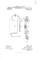
- FIG. 1 is a front elevation
- Fig. 2 a plan of breech mechanism with our improved extracting and ejecting mechanism applied thereto.
- Fig. 3 is a side elevation as seen from the right of Fig. 1.
- Fig. 4 is a local section taken approximately on the line 1. 1. of Fig. 1 through the central wedging piece.
- Fig. 5 is another local section taken approximately on the line 2. f2. of Fig. 1 through the boss of one of the ejecting arms.
- A is the breech end of the gun.
- .B is the swinging carrier and B its hinge pin.
- C is the breech screw and D the breech actuating hand lever.
- E is the horizontal spindle upon which are keyed the central wedging piece or extracting arm e and the two ejecting arms e e. rIhe keying of the said wedging piece and ejecting arms to the spindle E is effected by forming the latter with a longitudinal keyway with which a key c2 on the wedging piece engages, the dimensions of this key being such as to fit the said key-way (Fig. 4) and retain the wedging piece firmly fixed to the spindle so that no relative angular movement can take place between the wedging piece and the spindle.
- Each of the ejecting arms is also formed with a key e3 engaging with the said key-way in the spindle but these keys are yof less width than the keyway (Fig. 5) so as to permit of a small amount of idle mot-ion to take place between the spindle and the ejecting arms.
- the outer or free end of the said spindle E is furnished with the striking arm E" whose free end lies contiguous to the cam B2 with which the upper end or head of the hinge pin B is provided.
- This cam is forme with two active surfaces l) bx (Fig. 2) which are adapted to successi ely act upon the said striking arm E during the outward swinging movement of the carrier B.
- the surface b of the said cam operates to move the spindle E slowly while the extracting arm e is ot' the cjecting arms, and meansfor actuating said spindle when the breech is being opened.
- cartridge extracting' and ejecting 93 mechanism for ordnance the combination with the extracting' arm and the ejecting arms, of a spindle on which said arms are mounted, ay key on said extracting arm fitting in a keyway formed in said spindle, a key of less width than said kcyway on eachV of the ejecting arms, a striking arm on the outer end of said spindle, and a camY having two active surfaces, which operate on said performing its wedging action on the cartridge case, the ejecting arms c meanwhile remaining stationary by reason of the clearance ex (Fig. 5) that exists between the keyway on the spindle E and the keys e3 on the ejecting arms.
Landscapes
- Engineering & Computer Science (AREA)
- General Engineering & Computer Science (AREA)
- Wrapping Of Specific Fragile Articles (AREA)
Description
A. T. DAWSON & G. T. BUCKHAM. CARTRIDGE BXTDAGTING AND EJEGTING MDGHANISM PoR BREEGH LOADING ORDNANCB.
APPLICATION FILED 00T. 2, 1909. 1,022,469. Patented Apr. 9, 1912.
. z SHEETS-sum1.
MMIII.
i m.. A,........,.....H
CuLUMBlA PLANOGRAPH CO..WASHINGTDN. nA C.
A. T. DAWSON, & G. T. BUGKHAM. CARTRIDGE EXTRAGTING AND EJEGTING MEGHANISM FOR BREEGH LOADING DRDNANGE.
' APPLICATION FILED OCT. 2, 1909. 1,022,469.
Patented Apr. 9, 1912.
2 SHEETS-SHEET 2.
ARTHUR TREVOR DAWSON AND GEORGE THOMAS BUGKHAM,
LONDON, ENGLAND, ASSIGNORS TO VICKERS LIMITED,
ENGLAND.
tra earns 'rn OF WESTMINSTER, OIE WESTMINSTER,
CARTRDGE EXTRACTING AND EJECTING MECHANISIVI FOR IBB/EECH-LOADING ORDNANCE.
Application filed October Specification. of Letters Patent.
Patented Apr. 9, 1912.
serial No. 520,711.
To all Ywhom it may concern:
Be it known that we, ARTHUR TREvoR DAWSON and GEORGE THOMAS BUoxHAM, subjects of the King of Great Britain, both residing at 3Q Victoria street, lVestminster, inthe county of London, England, have invented certain new and useful Improvements in Cart-ridge Extracting and Ejecting Mechanism for Breech-Loading Ordnance, of which the following is a specification.
This invention relates to cartridge extracting and ejecting mechanism for-breech loading ordnance7 particularly quick ring guns in which the breech screw is rotatably mounted in a swinging carrier.
An extractor has heretofore been proposed comprising two ejecting arms and a central lip lying near the fulcrum of the extractor, the said lip being integral with the ejecting arms and acting to exert an initial powerful prising action. The said extractor is actuated by a cam surface which rst moves the extractor slowly and then quickly to eject the cartridge case by means of the aforesaid ejecting arms.
The chief object of the present invention is to devise a simple form of extracting and ejecting mechanism that shall be more owerful and eilicient in its action.
According to the present invention the aforesaid central wedging piece or extracting arm and the two eject-ing arms are mounted independently of each other on a spindle which is adapted to be actuated by a cam or the like on the carrier hinge pin. The arms are connected to the spindle in such manner that a certain amount of lost motion can take place between the wedging piece and the ejecting arms, so that the sai ejecting arms remain stationary during the action of the wedging piece. rI he horizontal spindle carries at its outer end a striking arm situated on the exterior of the gun and the head of the carrier hinge pin is formed to act as a cam and to engage with the striking arm on the horizontal spindle. The operation of this cam has the effect of Jfirst causing a slow wedging or gradual prisingaction on the cartridge case, through the extracting arm, and then, through ythe intervention of the ejecting arms, causing a sharp blow to be given to the prised cartridge case to eject it.
In order that the said invention may be clearly understood and readily carried into effect the same will be described more fully with reference to the accompanying drawings, in which Figure 1 is a front elevation, and Fig. 2 a plan of breech mechanism with our improved extracting and ejecting mechanism applied thereto. Fig. 3 is a side elevation as seen from the right of Fig. 1. Fig. 4 is a local section taken approximately on the line 1. 1. of Fig. 1 through the central wedging piece. Fig. 5 is another local section taken approximately on the line 2. f2. of Fig. 1 through the boss of one of the ejecting arms.
A is the breech end of the gun.
.B is the swinging carrier and B its hinge pin.
C is the breech screw and D the breech actuating hand lever.
E is the horizontal spindle upon which are keyed the central wedging piece or extracting arm e and the two ejecting arms e e. rIhe keying of the said wedging piece and ejecting arms to the spindle E is effected by forming the latter with a longitudinal keyway with which a key c2 on the wedging piece engages, the dimensions of this key being such as to fit the said key-way (Fig. 4) and retain the wedging piece firmly fixed to the spindle so that no relative angular movement can take place between the wedging piece and the spindle. Each of the ejecting arms is also formed with a key e3 engaging with the said key-way in the spindle but these keys are yof less width than the keyway (Fig. 5) so as to permit of a small amount of idle mot-ion to take place between the spindle and the ejecting arms. The outer or free end of the said spindle E is furnished with the striking arm E" whose free end lies contiguous to the cam B2 with which the upper end or head of the hinge pin B is provided. This cam is forme with two active surfaces l) bx (Fig. 2) which are adapted to successi ely act upon the said striking arm E during the outward swinging movement of the carrier B. The surface b of the said cam operates to move the spindle E slowly while the extracting arm e is ot' the cjecting arms, and meansfor actuating said spindle when the breech is being opened.
i. In cartridge extract-ing and ejecting mechanism for ordnance, t-he combination with the extracting arm and the' ejecting arms, of a spindle on which said arms are mounted, a key on said extract-ing arm itting in a keyway formed in said spindle, a key of less width than said keyway on each of the ejecting arms, a striking arm on the outer end of said spindle and a cam for actuating' said striking arm t0 rotate theV spin-V 70 dle when the breech is being opened.
5. In cartridge extracting and ejecting mechanism for ordnance, the combination Y' with the extracting arm arms, ot' a spindle on which said'arms are 75 mounted, a key on Said extracting arm iitting in a keyway formed in said spindle, a key of less width than said keyway on each of the ejecting arms, av striking arm on t-he outer end of said spindle, and a cam on the carrier hinge pin for actuating said striking arm to rotate the spindle. c
6. In cartridge extracting and ejecting mechanism for ordnance, the combination with the extract-ing arm and the eject-ing arms, of a spindle on which said arms are mounted, a key on said extracting arm it- Y ting in a ke-yway formed in said spindle, a key of less width than said keyway on each ot the ejecting arms, a striking arm on the outer end of said spindle, and a cam having two active surfaces which are adapted to successively act on the said striking arm to rotate the spindle. Y Y Y T. In cartridge extracting' and ejecting 93 mechanism for ordnance, the combination with the extracting' arm and the ejecting arms, of a spindle on which said arms are mounted, ay key on said extracting arm fitting in a keyway formed in said spindle, a key of less width than said kcyway on eachV of the ejecting arms, a striking arm on the outer end of said spindle, and a camY having two active surfaces, which operate on said performing its wedging action on the cartridge case, the ejecting arms c meanwhile remaining stationary by reason of the clearance ex (Fig. 5) that exists between the keyway on the spindle E and the keys e3 on the ejecting arms. By the time this clearance has been taken up by the movement of the spindle E the other surface 5X of the cam B2 acts upon the striking' arm E and imparts a sudden rapid movement to the spindle E together with the ejecting arms e tlius promptly ejecting the cartridge case from the breech chamber.
he principal advantage of this type of extractor is that the slow wedging action ou the cartridge case followed by the powerful throw ot' the cartridge case is obtained by independent extracting and ejecting arms instead of by a single piece of the kind rel ferred to above. Another advantage is that I the parts are simple in construction and nej l cessitate very little cutting a Yay of the effective section of the gun. The idle motion of the spindle E also obviates any additional cutting into the gun :tor the ejecting arms, which would otherwise be necessary to give free play to the wedging piece or extracting arm e prior to the ejecting arms coming into action.
that we claim and desire to secure by Letters Patent of the United States is :h
l. In cartridge extract-ing and ejecting mechanism for ordnance, the combination' with the ejecting arms and the short extracting arm between said ejecting arms, of a spindle on which said arms are mounted, and means for connecting the extracting arm and the ejecting arms with said spindle so that lost motion can take place between the extracting arm and the ejecting arms.
2. In cartridge extracting and ejecting mechanism for ordnance, the combination with the extracting arm and the ejecting arms of a spindle on which said arms are mounted, means for rigidly connecting the extracting arm with said spindle, and means for connecting the ejecting arms with the spindle so that relative movement can take place between said spindle and the ejecting arms.
3. In cartridge extracting mechanism for ordnance, the combination with the extracting arm and the eject-ing arms, of a spindle on which said arms are mounted, a key on said extracting arm litting in a ke 7way formed in said spindle, a key of less width than said keyway on each slowly for the extracting operation and then quickly for the ejecting operation.
In testimony whereof we aiiix our signatures in presence of two witnesses. ARTHUR VTREVOR DAIVSON.
GEORGE THOMAS BUCKHAM.
l `Witnesses and ejectin HENRY KING, ALFRED Peaks.
Copies of this patent may be obtained for ve cents each, by addressing the Gommissoner of Patents,
Washington, D. C. Y'
striking arm to lirst rotate the said spindle VY i
Priority Applications (1)
| Application Number | Priority Date | Filing Date | Title |
|---|---|---|---|
| US52071109A US1022469A (en) | 1909-10-02 | 1909-10-02 | Cartridge extracting and ejecting mechanism for breech-loading ordnance. |
Applications Claiming Priority (1)
| Application Number | Priority Date | Filing Date | Title |
|---|---|---|---|
| US52071109A US1022469A (en) | 1909-10-02 | 1909-10-02 | Cartridge extracting and ejecting mechanism for breech-loading ordnance. |
Publications (1)
| Publication Number | Publication Date |
|---|---|
| US1022469A true US1022469A (en) | 1912-04-09 |
Family
ID=3090766
Family Applications (1)
| Application Number | Title | Priority Date | Filing Date |
|---|---|---|---|
| US52071109A Expired - Lifetime US1022469A (en) | 1909-10-02 | 1909-10-02 | Cartridge extracting and ejecting mechanism for breech-loading ordnance. |
Country Status (1)
| Country | Link |
|---|---|
| US (1) | US1022469A (en) |
Cited By (1)
| Publication number | Priority date | Publication date | Assignee | Title |
|---|---|---|---|---|
| US2855828A (en) * | 1950-03-31 | 1958-10-14 | Philias H Girouard | Rapid fire gun turret apparatus |
-
1909
- 1909-10-02 US US52071109A patent/US1022469A/en not_active Expired - Lifetime
Cited By (1)
| Publication number | Priority date | Publication date | Assignee | Title |
|---|---|---|---|---|
| US2855828A (en) * | 1950-03-31 | 1958-10-14 | Philias H Girouard | Rapid fire gun turret apparatus |
Similar Documents
| Publication | Publication Date | Title |
|---|---|---|
| US325053A (en) | Athanase chtjchu | |
| US718719A (en) | Extractor for breech-loading ordnance. | |
| US939142A (en) | Firearm. | |
| US261648A (en) | Breech-loading fire-arm | |
| US778500A (en) | Self-cocking revolver. | |
| US1080268A (en) | Breech mechanism of ordnance. | |
| US898840A (en) | Breech mechanism of guns. | |
| US1163811A (en) | Lock mechanism of breech-loading guns. | |
| US798806A (en) | Ejector mechanism for shotguns. | |
| US845481A (en) | Gun. | |
| US704898A (en) | Breech mechanism. | |
| US1840478A (en) | Trigger and safety mechanism for sporting guns | |
| US258116A (en) | quick | |
| US526690A (en) | Walton c | |
| US229035A (en) | Breech-loading fire-arm | |
| US629142A (en) | Breech-loading firearm. | |
| US538810A (en) | Ander thorn | |
| US528228A (en) | Ejecting and cocking mechanism for breakdown guns | |
| US806313A (en) | Breech-loading small-arm. | |
| US1124427A (en) | Firearm. | |
| US510999A (en) | Ejector mechanism for breakdown guns | |
| US896669A (en) | Breech-operating mechanism for ordnance. | |
| US567224A (en) | deport | |
| US215445A (en) | Improvement in breech-loading fire-arms | |
| US475873A (en) | Lock and ejector mechanism for breakdown guns |