US10215835B1 - Estimating location of source of signal of interest - Google Patents
Estimating location of source of signal of interest Download PDFInfo
- Publication number
- US10215835B1 US10215835B1 US14/836,088 US201514836088A US10215835B1 US 10215835 B1 US10215835 B1 US 10215835B1 US 201514836088 A US201514836088 A US 201514836088A US 10215835 B1 US10215835 B1 US 10215835B1
- Authority
- US
- United States
- Prior art keywords
- soi
- tan
- location
- source
- matrix
- Prior art date
- Legal status (The legal status is an assumption and is not a legal conclusion. Google has not performed a legal analysis and makes no representation as to the accuracy of the status listed.)
- Active, expires
Links
- 238000005259 measurement Methods 0.000 claims abstract description 12
- 238000000034 method Methods 0.000 claims abstract description 11
- 239000011159 matrix material Substances 0.000 claims description 23
- 238000000354 decomposition reaction Methods 0.000 claims description 4
- 238000004458 analytical method Methods 0.000 description 1
- 238000010586 diagram Methods 0.000 description 1
- 238000011156 evaluation Methods 0.000 description 1
- 238000005562 fading Methods 0.000 description 1
- 230000014509 gene expression Effects 0.000 description 1
Images
Classifications
-
- G—PHYSICS
- G01—MEASURING; TESTING
- G01S—RADIO DIRECTION-FINDING; RADIO NAVIGATION; DETERMINING DISTANCE OR VELOCITY BY USE OF RADIO WAVES; LOCATING OR PRESENCE-DETECTING BY USE OF THE REFLECTION OR RERADIATION OF RADIO WAVES; ANALOGOUS ARRANGEMENTS USING OTHER WAVES
- G01S5/00—Position-fixing by co-ordinating two or more direction or position line determinations; Position-fixing by co-ordinating two or more distance determinations
- G01S5/02—Position-fixing by co-ordinating two or more direction or position line determinations; Position-fixing by co-ordinating two or more distance determinations using radio waves
- G01S5/04—Position of source determined by a plurality of spaced direction-finders
-
- G—PHYSICS
- G01—MEASURING; TESTING
- G01S—RADIO DIRECTION-FINDING; RADIO NAVIGATION; DETERMINING DISTANCE OR VELOCITY BY USE OF RADIO WAVES; LOCATING OR PRESENCE-DETECTING BY USE OF THE REFLECTION OR RERADIATION OF RADIO WAVES; ANALOGOUS ARRANGEMENTS USING OTHER WAVES
- G01S5/00—Position-fixing by co-ordinating two or more direction or position line determinations; Position-fixing by co-ordinating two or more distance determinations
- G01S5/02—Position-fixing by co-ordinating two or more direction or position line determinations; Position-fixing by co-ordinating two or more distance determinations using radio waves
- G01S5/0278—Position-fixing by co-ordinating two or more direction or position line determinations; Position-fixing by co-ordinating two or more distance determinations using radio waves involving statistical or probabilistic considerations
Definitions
- the invention generally pertains to telecommunications and is more specifically directed to estimating the location of the source of a signal of interest (SOI).
- SOI signal of interest
- Known techniques for estimating the location of the source of a SOI are based upon processing a plurality of directional samples of the SOI that are sensed by a respective plurality of disparately located signal receiving systems.
- the invention provides a method of estimating the location of the source of a signal of interest (SOI), comprising the steps of:
- the invention By processing a power variable measurement of a SOI in combination with sensed directional samples of the SOI obtained by at least one signal receiving system at disparately located signal receiving locations in order to estimate the location of the source of the SOI, the invention enables more accurate estimations of the source of the SOI in various environments that cause an often unpredictable variety of multipath signal losses.
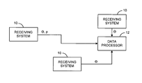
- FIG. 1 is a block diagram showing an exemplary embodiment of apparatus for performing the method of the invention.
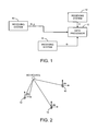
- FIG. 2 illustrates exemplary locations of the receiving system(s) shown in FIG. 1 with respect to the sources of a SOI.
- an exemplary embodiment of apparatus for performing the method of the invention includes a plurality of receiving systems 10 at k disparately located signal receiving locations and a data processor 12 .
- One of the receiving systems 10 may be airborne.
- a single receiving system receives signals at k disparately located signal receiving locations.
- the data processor 12 preferably is located in common with one of the data receiving systems 10 .
- Each receiving system 10 includes an antenna, a telecommunications receiver, and a signal processor for providing directional data ( ⁇ ) samples of signals received by the antenna from the source of the SOI.
- the directional data ( ⁇ ) samples represent the line of bearing (LoB) of the respective receiving system 10 in relation to North from the kth receiving location to the source of the SOI.
- At least one of the receiving systems 10 senses the amplitude of the signals received by the antenna from the source of the SOI; and the sensed amplitude of the received signals is processed by the signal processor to measure a power variable ( ⁇ ) of the signals received from the source of the SOI.
- the data processor 12 contains a computer and non-transitory computer readable storage media that includes computer executable program instructions for causing the computer to perform and/or enable various ones of the processing steps that are described herein. These instructions are stored in the non-transitory computer readable storage media of the computer when the computer is manufactured and/or upon being downloaded via the Internet or from a portable non-transitory computer readable storage media containing such instructions.
- the data processor 12 processes the directional data ( ⁇ ) samples provided the plurality of receiving systems 10 in combination with the power variable ( ⁇ ) measurements provided by at least one of the receiving systems 10 to estimate the location of the source of the SOI.
- the data processor 12 is used to precondition the sensed directional data ( ⁇ ) samples of the SOI and the measured power variables ( ⁇ ) by organizing such directional data ( ⁇ ) samples and such measured power variables ( ⁇ ) into spatial clusters. Such clustering is useful for removing outliers and focusing on trends for a measurement series. For directional data, a wide spread of series is indicative of a severe multipath of the received signals.
- Clustering is important in urban areas for power estimation because the amplitude of the received signal follows a K-Rician distribution. Measuring the amplitude of a received SOI reveals a fading regime by estimating the K parameter in a K-Rician distribution and thereby enables an evaluation of the amount of loss-of-signal (LOS) energy versus multipath effects.
- LOS loss-of-signal
- FIG. 2 which illustrates different exemplary receiving locations of the receiving systems 10 , without regard to elevation, with respect to the source of the SOI, a two-dimensional estimation by the data processor 12 of the location of the source of the SOI is accomplished by assuming that:
- x k sign ⁇ ( cos ⁇ ( ⁇ k ) ) ⁇ ( P k P 0 ) 1 / ( - ⁇ ) ⁇ ( 1 + tan ⁇ ( ⁇ k ) 2 ) - 1 / 2 ;
- y k sign ⁇ ( sin ⁇ ( ⁇ k ) ) ⁇ ( P k P 0 ) 1 / ( - ⁇ ) ⁇ ( 1 + 1 tan ⁇ ( ⁇ k ) 2 ) - 1 / 2 ;
- the data processor 12 further performs the step of:
- the data processor 12 further performs the step of:
- the CEP computation is derived from a Gudrun H ⁇ ye paper, “Analyses of the geolocation accuracy that can be obtained from shipborne sensors by use of time difference of arrival (TDOA), scanphase, and angle of arrival (AOA) measurements”.
- TDOA time difference of arrival
- AOA angle of arrival
- V The parameters measured define V as:
- the Matrix C is expressed as:
- the CRLB Covariance Matrix K [ CD ⁇ 1 C T ] ⁇ 1 .
- a preferred Matlab Code for Equation 13 is as follows:
- A [reshape([ones(N,1)*[1 0]].′,2*N,1) reshape([ones(N,1)*[0 1]].′,2*N,1) ⁇ reshape([Cx Cy]′,2*N,1)];
- the provided samples are processed by the data processor 12 in combination with the power variable ( ⁇ ) measurements provided by at least one of the receiving systems 10 to estimate the location of the source of the SOI.
- the assumptions, mathematical expressions and equations applied as set forth above to estimate the location of the source of the SOI with regard to the two-dimensional embodiment discussed above with reference to FIG. 2 without regard to elevation also can be applied to estimate the location of the source of the SOI in the exemplary three-dimensional-parameter-value embodiment.
Landscapes
- Physics & Mathematics (AREA)
- Engineering & Computer Science (AREA)
- General Physics & Mathematics (AREA)
- Radar, Positioning & Navigation (AREA)
- Remote Sensing (AREA)
- Probability & Statistics with Applications (AREA)
- Position Fixing By Use Of Radio Waves (AREA)
Abstract
A method of estimating the location of the source of a signal of interest (SOI), includes the steps of:
-
- (a) sensing a plurality of directional samples of the SOI by using at least one signal receiving system at disparately located signal receiving locations;
- (b) with at least one of the signal receiving systems, measuring the power variable of the received SOI; and
- (c) processing the sensed directional samples of the SOI in combination with the power variable measurement of the SOI to estimate the location of the source of the SOI.
Description
The invention generally pertains to telecommunications and is more specifically directed to estimating the location of the source of a signal of interest (SOI).
Known techniques for estimating the location of the source of a SOI are based upon processing a plurality of directional samples of the SOI that are sensed by a respective plurality of disparately located signal receiving systems.
The invention provides a method of estimating the location of the source of a signal of interest (SOI), comprising the steps of:
(a) sensing a plurality of directional samples of the SOI by using at least one signal receiving system at disparately located signal receiving locations;
(b) with at least one of the signal receiving systems, measuring the power variable of the received SOI; and
(c) processing the sensed directional samples of the SOI in combination with the power variable measurement of the SOI to estimate the location of the source of the SOI.
By processing a power variable measurement of a SOI in combination with sensed directional samples of the SOI obtained by at least one signal receiving system at disparately located signal receiving locations in order to estimate the location of the source of the SOI, the invention enables more accurate estimations of the source of the SOI in various environments that cause an often unpredictable variety of multipath signal losses.
Additional features of the present invention are described with reference to the detailed description.
Referring to FIG. 1 , an exemplary embodiment of apparatus for performing the method of the invention includes a plurality of receiving systems 10 at k disparately located signal receiving locations and a data processor 12. One of the receiving systems 10 may be airborne. In an alternative embodiment (not shown) a single receiving system receives signals at k disparately located signal receiving locations.
The data processor 12 preferably is located in common with one of the data receiving systems 10.
Each receiving system 10 includes an antenna, a telecommunications receiver, and a signal processor for providing directional data (θ) samples of signals received by the antenna from the source of the SOI. The directional data (θ) samples represent the line of bearing (LoB) of the respective receiving system 10 in relation to North from the kth receiving location to the source of the SOI.
At least one of the receiving systems 10 senses the amplitude of the signals received by the antenna from the source of the SOI; and the sensed amplitude of the received signals is processed by the signal processor to measure a power variable (σ) of the signals received from the source of the SOI.
The data processor 12 contains a computer and non-transitory computer readable storage media that includes computer executable program instructions for causing the computer to perform and/or enable various ones of the processing steps that are described herein. These instructions are stored in the non-transitory computer readable storage media of the computer when the computer is manufactured and/or upon being downloaded via the Internet or from a portable non-transitory computer readable storage media containing such instructions.
The data processor 12 processes the directional data (θ) samples provided the plurality of receiving systems 10 in combination with the power variable (σ) measurements provided by at least one of the receiving systems 10 to estimate the location of the source of the SOI.
It is preferred that prior to such processing, the data processor 12 is used to precondition the sensed directional data (θ) samples of the SOI and the measured power variables (σ) by organizing such directional data (θ) samples and such measured power variables (σ) into spatial clusters. Such clustering is useful for removing outliers and focusing on trends for a measurement series. For directional data, a wide spread of series is indicative of a severe multipath of the received signals.
Clustering is important in urban areas for power estimation because the amplitude of the received signal follows a K-Rician distribution. Measuring the amplitude of a received SOI reveals a fading regime by estimating the K parameter in a K-Rician distribution and thereby enables an evaluation of the amount of loss-of-signal (LOS) energy versus multipath effects.
Referring to FIG. 2 , which illustrates different exemplary receiving locations of the receiving systems 10, without regard to elevation, with respect to the source of the SOI, a two-dimensional estimation by the data processor 12 of the location of the source of the SOI is accomplished by assuming that:
-
- i. the location of the source of the SOI is stationary and expressed as S=(x,y);
- ii. the locations at which the directional samples are sensed are defined by a matrix Z with column k expressing the Zk receiving location for the receiving system as a pair (Zkx, Zky);
- iii. the line of bearing (LoB) in relation to North from the kth receiving location to the source of the SOI is expressed as θk;
- iv. the environment is such that there exists a signal-power (PK) relationship between the location of the source of the SOI and the locations at which the directional samples are sensed, with said relationship being expressed by the following equation: Pk=P0|Zk−S|−γ, where Po is the power of the SOI and γ is a signal-path-loss factor for said environment;
- v. the location of the SOI with respect to the locations at which the directional samples are sensed is defined as a pair (xk, yk); and
- vi. rk is defined as the range from the sensor to the SOI; and
wherein the power variable ρ=(P0)1/γ;
and by thedata processor 12 performing the following steps: and by thedata processor 12 performing the following steps:
(a) preparing a system of equations:
A. r k 2 =x r 2 +y k 2 (Eq. 1),
B. P k =P 0 |Z k −S| −γ =P 0 r k −γ (Eq. 2),
C. γk=tan(θk)x k (Eq. 3); and
D. {right arrow over (S)}={right arrow over (Z k)}+{right arrow over (r k)} (Eq. 4);
A. r k 2 =x r 2 +y k 2 (Eq. 1),
B. P k =P 0 |Z k −S| −γ =P 0 r k −γ (Eq. 2),
C. γk=tan(θk)x k (Eq. 3); and
D. {right arrow over (S)}={right arrow over (Z k)}+{right arrow over (r k)} (Eq. 4);
(b) using (Eq. 2) to express:
(c) using (Eq. 5) to rewrite (Eq. 1) as:
(d) using the angle of arrival (AoA) of each sensed directional sample to resolve the + ambiguity in (Eq. 6) and (Eq.7) by rewriting (Eq. 6) and (Eq.7) as:
(e) using (Eq. 4) to rewrite (Eq. 6) and (Eq.7) as:
and
(f) estimating the location (x, y) of the source of the SOI with respect to the vector position value (b) of the respective receiving location (K) by expressing (Eq. 10 and Eq. 11) as:
where the matrix A's 2Kth and (2K+1)th rows are given by:
The data processor 12 further performs the step of:
(g) using the Moore Penrose pseudo inverse to a MMSE (minimum mean square error) solution of the vector position value (b) of the respective receiving locations (K) to solve for (x,y,p)
The data processor 12 further performs the step of:
(h) computing and displaying a circle-error probability (CEP) of
In an exemplary embodiment, the CEP computation is derived from a Gudrun Høye paper, “Analyses of the geolocation accuracy that can be obtained from shipborne sensors by use of time difference of arrival (TDOA), scanphase, and angle of arrival (AOA) measurements”.
The measurements for the power variable (σ) and the K AOA samples (θ) are regrouped in a vector V that depends on both the transmitter location S=(x,y), and the Kth receiving location, which is defined by a pair (Zkx, Zky).
The parameters measured define V as:
The partial derivative of the parameters with respect to the source of the SOI, define:
For power estimates express:
The Matrix C is expressed as:
The K×K variance matrix D is expressed as:
diag(D)=(σθ1 ,σP 2 , . . . ,σθ K ,σP K ).
diag(D)=(σθ
The CRLB Covariance Matrix K given by
K=[CD −1 C T]−1.
K=[CD −1 C T]−1.
Orientation and size of the semi major and semi-minor axes for the CEP ellipses can be obtained by the decomposition of K in its eigenvectors Vn and eigenvalues en that form the diagonal of the matrix E and forming the matrix L=V√{square root over (E)}.
Orientation and size of the semi major and semi-minor axes for the CEP ellipses can be obtained by the decomposition of K in its eigenvectors Vn and eigenvalues en that form the diagonal of the matrix E and forming the matrix L=V√{square root over (E)}.
Points on the error of position ellipse are given by pairs (qx,qy) points for angle beta that meet the relationship:
In the display, the ellipse is centered on the emitter location (x,y) estimated by with relationship in (Eq. 13).
A preferred Matlab Code for Equation 13 is as follows:
clear all
N=50; %# of measurements
gamma=−3.0; % gamma we are guessing
P0=pi; % Some nominal power
gammastd=0.25; % gamma deviations
pwrstd=1.5; % power deviations in dB
aoastd=5; % AoA deviations in std
range=1;
S=(randn(1,2))*range*1500+(1+i)*200;S=S(1)+i*S(2); % set the source
Z=[1*randn(N,1)*0.01 1*randn(N,1)]*range*1000;Z=Z(:,1)+i*Z(:,2); % set the receiver locations
% Simulate and Compute noisy AoA
theta=angle(S−Z)*180/pi+randn(N,1)*aoastd
% Simulate and Compute imperfect power measurements
gammaset=gamma+randn*gammastd;
P=P0*abs(S−Z).^(gammaset).*(10.^(randn(N,1)*pwrstd/10));
% Define coefficients and matrices
Cx=sign(cos d(theta)).*(P).^(1/gamma).*(1+tan d(theta).^2).^(−1/2);
Cy=sign(sin d(theta)).*(P).^(1/gamma).*(1+tan d(theta).^−2).^(−1/2);
A=[reshape([ones(N,1)*[1 0]].′,2*N,1) reshape([ones(N,1)*[0 1]].′,2*N,1) −reshape([Cx Cy]′,2*N,1)];
B=reshape([real(Z) imag(Z)]′,2*N,1)
% compute Pinv for MMSE solution
sol=pinv(A)*B
pseudosol=sol(1)+i*sol(2);
[pseudosol S]
pp0=sol(3)^(−gamma) % Sanity Check
%% All plots below
figure(10);
clf;
plot(Z,‘bo’);hold on;
axis(‘square’)
axis(‘square’);%[−1 1−1 1]*range*4);
figure(14);
hist(abs(ZZ2+Z−S),[0:10:2000]);
figure(10)
plot(ZZ2+Z,‘k.’)
plot(S,‘rs’,‘LineWidth’,3);
axis(‘equal’);
plot(pseudosol,‘bs’,‘LineWidth’,3);plot([Z+0 Z+500*exp(i*theta/180*pi)].‘,’--’);
title([‘AOA std=’ num2str(aoastd) ‘; PWR std=’ num2str(pwrstd) ‘; Gamma std=’
num2str(gammastd)]);
xlabel(‘m’);ylabel(‘m’);
legend(‘positions’,‘estimates’,‘S’,‘Location Pointer Estimate’,‘LOB from AoA’)
In an alternative exemplary embodiment, in which the directional data samples (θ) provided the receiving systems 10 provided by the sensing systems include three-dimensional-parameter values of the directional data, the provided samples are processed by the data processor 12 in combination with the power variable (σ) measurements provided by at least one of the receiving systems 10 to estimate the location of the source of the SOI. The assumptions, mathematical expressions and equations applied as set forth above to estimate the location of the source of the SOI with regard to the two-dimensional embodiment discussed above with reference to FIG. 2 without regard to elevation also can be applied to estimate the location of the source of the SOI in the exemplary three-dimensional-parameter-value embodiment.
The benefits specifically stated herein do not necessarily apply to every conceivable embodiment of the present invention. Further, such stated benefits of the present invention are only examples and should not be construed as the only benefits of the present invention.
While the above description contains many specificities, these specificities are not to be construed as limitations on the scope of the present invention, but rather as examples of the preferred embodiments described herein. Other variations are possible and the scope of the present invention should be determined not by the embodiments described herein but rather by the claims and their legal equivalents.
Regarding the method claims, except for those steps that can only occur in the sequence in which they are recited, and except for those steps for which the occurrence of a given sequence is specifically recited or must be inferred, the steps of the method claims do not have to occur in the sequence in which they are recited.
Claims (6)
1. A method of estimating the location of the source of a signal of interest (SOI), comprising the steps of:
(a) sensing a plurality of directional samples of the SOI at disparately located signal receiving locations by using at least one signal receiving system;
(b) with said at least one signal receiving system, measuring a power variable of the received SOI; and
(c) processing the sensed directional samples of the SOI in combination with the power variable measurement of the SOI to estimate the location of the source of the SOI;
assuming that:
i. the location of the source, without regard to elevation, of the SOI is stationary and expressed as S=(x,y);
ii. the locations at which the directional samples are sensed are defined by a matrix Z with column k expressing the kth receiving location as a pair (Zkx, Zky);
iii. the line of bearing (LoB) in relation to North from the kth receiving location to the source of the SOI is expressed as θk;
iv. the environment is such that there exists a signal-power (PK) relationship between the location of the source of the SOI and the locations at which the directional samples are sensed, with said relationship being expressed by the following equation: Pk=P0|Zk−S|−γ, where Po is the power of the SOI and γ is a signal-path-loss factor for said environment;
v. the location of the SOI with respect to the locations at which the directional samples are sensed is defined as a pair (xk, yk); and
vi. rk is defined as the range from the sensor to the SOI; and
wherein the power variable ρ=(P0)1/γ;
step (c) comprises the steps of:
(d) preparing a system of equations:
A. r k 2 =x r 2 +y k 2 (Eq. 1),
B. P k =P 0 |Z k −S| −γ =P 0 r k −γ (Eq. 2),
C. γk=tan(θk)x k (Eq. 3); and
D. {right arrow over (S)}={right arrow over (Z k)}+{right arrow over (r k)} (Eq. 4);
A. r k 2 =x r 2 +y k 2 (Eq. 1),
B. P k =P 0 |Z k −S| −γ =P 0 r k −γ (Eq. 2),
C. γk=tan(θk)x k (Eq. 3); and
D. {right arrow over (S)}={right arrow over (Z k)}+{right arrow over (r k)} (Eq. 4);
(e) using (Eq. 2) to express:
(f) using (Eq. 5) to rewrite (Eq. 1) as:
(g) using the angle of arrival (AoA) of each sensed directional sample to resolve the + ambiguity in (Eq. 6) and (Eq.7) by rewriting (Eq. 6) and (Eq.7) as:
(h) using (Eq. 4) to rewrite (Eq. 6) and (Eq.7) as:
and
(i) estimating the location (x, y) of the source of the SOI with respect to the vector position value (b) of the respective receiving location (K) by expressing (Eq. 10 and Eq. 11) as
where the matrix A's 2Kth and (2K+1)th rows are given by:
and b kth and (k+1)th values are
2. The method according to claim 1 , wherein step (c) further comprises the step of:
(j) using the Moore Penrose pseudo inverse to a MMSE (minimum mean square error) solution of the vector position value (b) of the respective receiving location (K) to solve for (x,y,p)
3. The method according to claim 2 , further comprising the step of:
(k) computing points for display of a circle-error probability (CEP) ellipse,
wherein the points on the ellipse are given by pairs (qx, qy) points for angle beta that meet the relationship:
wherein orientation and size of semi-major and semi-minor axes for the CEP ellipse being obtained by the decomposition of K in its eigenvectors Vn and eigenvalues en to thereby form a diagonal of a matrix E and form the matrix L=V√{square root over (E)};
wherein V is defined by measured parameters as:
wherein a CRLB Covariance Matrix K is given by
K=[CD −1 C T]−1,
K=[CD −1 C T]−1,
with the Matrix C being expressed as:
and
with the K×K variance matrix D being expressed as:
diag(D)=(σθ1 ,σP 2 , . . . ,σθ k ).
diag(D)=(σθ
4. A non-transitory computer readable storage medium for use with a computer for estimating the location of the source of a signal of interest (SOI) by processing sensed directional samples of the SOI in combination with a power variable measurement of the SOI,
wherein the computer readable storage medium contains computer executable program instructions for causing the computer to make said estimate in accordance with the following computer processing steps:
wherein:
i. the location of the source of the SOI is stationary and expressed as S=(x,y);
ii. the locations at which the directional samples are sensed are defined by a matrix Z with column k expressing the kth receiving location as a pair (Zkx, Zky);
iii. the line of bearing (LoB) in relation to North from the kth receiving location to the source of the SOI is expressed as θk;
iv. the environment is such that there exists a signal-power (PK) relationship between the location of the source of the SOI and the locations at which the directional samples are sensed, with said relationship being expressed by the following equation: Pk=P0|Zk−S|−γ, where Po is the power of the SOI and γ is a signal-path-loss factor for said environment;
v. the location of the SOI with respect to the locations at which the directional samples are sensed is defined as a pair (xk, yk); and
vi. rk is defined as the range from the sensor to the SOI; and
wherein the power variable ρ=(P0)1/γ;
(a) preparing a system of equations:
A. r k 2 =x r 2 +y k 2 (Eq. 1),
B. P k =P 0 |Z k −S| −γ =P 0 r k −γ (Eq. 2),
C. γk=tan(θk)x k (Eq. 3); and
D. {right arrow over (S)}={right arrow over (Z k)}+{right arrow over (r k)} (Eq. 4);
A. r k 2 =x r 2 +y k 2 (Eq. 1),
B. P k =P 0 |Z k −S| −γ =P 0 r k −γ (Eq. 2),
C. γk=tan(θk)x k (Eq. 3); and
D. {right arrow over (S)}={right arrow over (Z k)}+{right arrow over (r k)} (Eq. 4);
(b) using (Eq. 2) to express:
(c) using (Eq. 5) to rewrite (Eq. 1) as:
(d) using the angle of arrival (AoA) of each sensed directional sample to resolve the + ambiguity in (Eq. 6) and (Eq.7) by rewriting (Eq. 6) and (Eq.7) as:
(e) using (Eq. 4) to rewrite (Eq. 6) and (Eq.7) as:
and
(f) estimating the location (x, y) of the source of the SOI with respect to the vector position value (b) of the respective receiving location (K) by expressing (Eq. 10 and Eq. 11) as
where the matrix A's 2Kth and (2K+1)th rows are given by:
5. The non-transitory computer readable storage medium according to claim 4 , wherein the computer readable storage medium further contains computer executable program instructions for causing the computer to perform the step of:
(g) using the Moore Penrose pseudo inverse to a MMSE (minimum mean square error) solution of the vector position value (b) of the respective receiving locations (K) to solve for (x,y,p)
6. The non-transitory computer readable storage medium according to claim 5 , wherein the computer readable storage medium further contains computer executable program instructions for causing the computer to perform the step of:
(h) computing points for display of a circle-error probability (CEP) ellipse,
wherein the points on the ellipse are given by pairs (qx, qy) points for angle beta that meet the relationship:
wherein orientation and size of semi-major and semi-minor axes for the CEP ellipse being obtained by the decomposition of K in its eigenvectors Vn and eigenvalues en to thereby form a diagonal of a matrix E and form the matrix L=V√{square root over (E)};
wherein V is defined by measured parameters as:
wherein a CRLB Covariance Matrix K is given by
K=[CD −1 C T]−1,
K=[CD −1 C T]−1,
with the Matrix C being expressed as:
and
with the K×K variance matrix D being expressed as:
diag(D)=(σθ1 ,σP 2 , . . . ,σθ K ,σP K ).
diag(D)=(σθ
Priority Applications (1)
| Application Number | Priority Date | Filing Date | Title |
|---|---|---|---|
| US14/836,088 US10215835B1 (en) | 2015-08-26 | 2015-08-26 | Estimating location of source of signal of interest |
Applications Claiming Priority (1)
| Application Number | Priority Date | Filing Date | Title |
|---|---|---|---|
| US14/836,088 US10215835B1 (en) | 2015-08-26 | 2015-08-26 | Estimating location of source of signal of interest |
Publications (1)
| Publication Number | Publication Date |
|---|---|
| US10215835B1 true US10215835B1 (en) | 2019-02-26 |
Family
ID=65410628
Family Applications (1)
| Application Number | Title | Priority Date | Filing Date |
|---|---|---|---|
| US14/836,088 Active 2036-06-04 US10215835B1 (en) | 2015-08-26 | 2015-08-26 | Estimating location of source of signal of interest |
Country Status (1)
| Country | Link |
|---|---|
| US (1) | US10215835B1 (en) |
Cited By (2)
| Publication number | Priority date | Publication date | Assignee | Title |
|---|---|---|---|---|
| JP2021139805A (en) * | 2020-03-06 | 2021-09-16 | 日本電業工作株式会社 | Radio detector |
| US12253593B1 (en) * | 2023-11-20 | 2025-03-18 | Sr Technologies, Inc. | Geo-locating of wireless devices using squared residuals from round trip time and angle of arrival vectors |
Citations (13)
| Publication number | Priority date | Publication date | Assignee | Title |
|---|---|---|---|---|
| US3184739A (en) * | 1960-10-14 | 1965-05-18 | Franklin Frederick | Method of tracking radar targets in presence of jamming |
| GB2196183A (en) * | 1986-10-08 | 1988-04-20 | Devon County Council | Antenna calibration |
| US4751511A (en) * | 1984-05-24 | 1988-06-14 | Fujitsu Limited | Method and apparatus for estimating trajectory |
| US5765166A (en) * | 1996-04-23 | 1998-06-09 | Raytheon Company | Use of symmetric multiprocessors for multiple hypothesis tracking |
| US5930202A (en) * | 1996-11-20 | 1999-07-27 | Gte Internetworking Incorporated | Acoustic counter-sniper system |
| US5959580A (en) * | 1994-11-03 | 1999-09-28 | Ksi Inc. | Communications localization system |
| US20030069024A1 (en) * | 2001-10-09 | 2003-04-10 | Kennedy Joseph P. | System and method for geolocating a wireless mobile unit from a single base station using repeatable ambiguous measurements |
| US6670920B1 (en) * | 2002-08-15 | 2003-12-30 | Bae Systems Information And Electronic Systems Integration Inc. | System and method for single platform, synthetic aperture geo-location of emitters |
| US7092726B2 (en) * | 2003-12-29 | 2006-08-15 | Motorola, Inc. | Method and system for determining a location using a plurality of selected initial location estimates |
| WO2008099390A2 (en) * | 2007-02-12 | 2008-08-21 | Mobileaccess Networks Ltd. | Indoor location determination |
| US7518543B2 (en) * | 2002-06-14 | 2009-04-14 | Totalforsvarets Forskningsinstitut | Method for determining positions of targets by bistatic measurements using signals scattered by the targets |
| US8150567B2 (en) * | 2006-01-19 | 2012-04-03 | Thales | Device for control of relative position(s) by measurements of power, for a spacecraft of a group of spacecraft in formation |
| US8674880B2 (en) * | 2008-11-07 | 2014-03-18 | Thales | Method of determining the direction of arrival of a high-frequency electromagnetic wave |
-
2015
- 2015-08-26 US US14/836,088 patent/US10215835B1/en active Active
Patent Citations (13)
| Publication number | Priority date | Publication date | Assignee | Title |
|---|---|---|---|---|
| US3184739A (en) * | 1960-10-14 | 1965-05-18 | Franklin Frederick | Method of tracking radar targets in presence of jamming |
| US4751511A (en) * | 1984-05-24 | 1988-06-14 | Fujitsu Limited | Method and apparatus for estimating trajectory |
| GB2196183A (en) * | 1986-10-08 | 1988-04-20 | Devon County Council | Antenna calibration |
| US5959580A (en) * | 1994-11-03 | 1999-09-28 | Ksi Inc. | Communications localization system |
| US5765166A (en) * | 1996-04-23 | 1998-06-09 | Raytheon Company | Use of symmetric multiprocessors for multiple hypothesis tracking |
| US5930202A (en) * | 1996-11-20 | 1999-07-27 | Gte Internetworking Incorporated | Acoustic counter-sniper system |
| US20030069024A1 (en) * | 2001-10-09 | 2003-04-10 | Kennedy Joseph P. | System and method for geolocating a wireless mobile unit from a single base station using repeatable ambiguous measurements |
| US7518543B2 (en) * | 2002-06-14 | 2009-04-14 | Totalforsvarets Forskningsinstitut | Method for determining positions of targets by bistatic measurements using signals scattered by the targets |
| US6670920B1 (en) * | 2002-08-15 | 2003-12-30 | Bae Systems Information And Electronic Systems Integration Inc. | System and method for single platform, synthetic aperture geo-location of emitters |
| US7092726B2 (en) * | 2003-12-29 | 2006-08-15 | Motorola, Inc. | Method and system for determining a location using a plurality of selected initial location estimates |
| US8150567B2 (en) * | 2006-01-19 | 2012-04-03 | Thales | Device for control of relative position(s) by measurements of power, for a spacecraft of a group of spacecraft in formation |
| WO2008099390A2 (en) * | 2007-02-12 | 2008-08-21 | Mobileaccess Networks Ltd. | Indoor location determination |
| US8674880B2 (en) * | 2008-11-07 | 2014-03-18 | Thales | Method of determining the direction of arrival of a high-frequency electromagnetic wave |
Cited By (2)
| Publication number | Priority date | Publication date | Assignee | Title |
|---|---|---|---|---|
| JP2021139805A (en) * | 2020-03-06 | 2021-09-16 | 日本電業工作株式会社 | Radio detector |
| US12253593B1 (en) * | 2023-11-20 | 2025-03-18 | Sr Technologies, Inc. | Geo-locating of wireless devices using squared residuals from round trip time and angle of arrival vectors |
Similar Documents
| Publication | Publication Date | Title |
|---|---|---|
| US8054226B2 (en) | Method for estimating location of nodes in wireless networks | |
| KR102449214B1 (en) | Apparatus for estimating angle of arrival and method for estimating angle of arrival using same | |
| US7453400B2 (en) | Multiplatform TDOA correlation interferometer geolocation | |
| US8878725B2 (en) | System and method for geolocation of multiple unknown radio frequency signal sources | |
| CN106658713B (en) | Single base station mobile user positioning method based on multi-parameter estimation | |
| IL264289A (en) | System and method for characterizing properties of em signals | |
| US11074699B2 (en) | Method for determining a protection radius of a vision-based navigation system | |
| US20100315290A1 (en) | Globally-convergent geo-location algorithm | |
| US20120235864A1 (en) | System and Method for Three-Dimensional Geolocation of Emitters Based on Energy Measurements | |
| US20150241545A1 (en) | Single Platform Doppler Geolocation | |
| Fridman et al. | Inversion of backscatter ionograms and TEC data for over-the-horizon radar | |
| CN112414554A (en) | Sea surface salinity obtaining method, device, equipment and medium | |
| JP4592506B2 (en) | Uplink interference source locating apparatus and method | |
| EP1682923B1 (en) | Method for localising at least one emitter | |
| US10215835B1 (en) | Estimating location of source of signal of interest | |
| US12342312B2 (en) | Positioning measurements | |
| CN103544376B (en) | Shortwave fixed monitoring station direction finding data correcting method | |
| CN105259533B (en) | The three stage reaching time-difference localization methods based on multidimensional scaling subspace analysis | |
| EP3145093A1 (en) | Calibration device | |
| CN108513355B (en) | Single base station-based network positioning method, device and equipment | |
| Maguire et al. | Low frequency radio polarization sensor with applications in attitude estimation | |
| RU2647495C1 (en) | Multiplicative difference-relative method for determination of coordinates of position of pulsed radio-frequency source | |
| CN116482633A (en) | Multi-base moving target localization method with ability to reduce deviation | |
| CN108287353A (en) | Space-based unmanned plane communications satellite positioning and tracing method | |
| Holland et al. | Littoral environmental reconnaissance using tactical imagery from unmanned aircraft systems |
Legal Events
| Date | Code | Title | Description |
|---|---|---|---|
| STCF | Information on status: patent grant |
Free format text: PATENTED CASE |
|
| CC | Certificate of correction | ||
| MAFP | Maintenance fee payment |
Free format text: PAYMENT OF MAINTENANCE FEE, 4TH YEAR, LARGE ENTITY (ORIGINAL EVENT CODE: M1551); ENTITY STATUS OF PATENT OWNER: LARGE ENTITY Year of fee payment: 4 |