US10208667B2 - Nose cone with an aft support ring for radial attachment - Google Patents
Nose cone with an aft support ring for radial attachment Download PDFInfo
- Publication number
- US10208667B2 US10208667B2 US15/026,692 US201415026692A US10208667B2 US 10208667 B2 US10208667 B2 US 10208667B2 US 201415026692 A US201415026692 A US 201415026692A US 10208667 B2 US10208667 B2 US 10208667B2
- Authority
- US
- United States
- Prior art keywords
- support ring
- spinner
- aft support
- interference fitting
- stepped portion
- Prior art date
- Legal status (The legal status is an assumption and is not a legal conclusion. Google has not performed a legal analysis and makes no representation as to the accuracy of the status listed.)
- Active, expires
Links
Images


Classifications
-
- F—MECHANICAL ENGINEERING; LIGHTING; HEATING; WEAPONS; BLASTING
- F02—COMBUSTION ENGINES; HOT-GAS OR COMBUSTION-PRODUCT ENGINE PLANTS
- F02C—GAS-TURBINE PLANTS; AIR INTAKES FOR JET-PROPULSION PLANTS; CONTROLLING FUEL SUPPLY IN AIR-BREATHING JET-PROPULSION PLANTS
- F02C7/00—Features, components parts, details or accessories, not provided for in, or of interest apart form groups F02C1/00 - F02C6/00; Air intakes for jet-propulsion plants
- F02C7/04—Air intakes for gas-turbine plants or jet-propulsion plants
-
- B—PERFORMING OPERATIONS; TRANSPORTING
- B64—AIRCRAFT; AVIATION; COSMONAUTICS
- B64C—AEROPLANES; HELICOPTERS
- B64C11/00—Propellers, e.g. of ducted type; Features common to propellers and rotors for rotorcraft
- B64C11/02—Hub construction
- B64C11/14—Spinners
-
- F—MECHANICAL ENGINEERING; LIGHTING; HEATING; WEAPONS; BLASTING
- F01—MACHINES OR ENGINES IN GENERAL; ENGINE PLANTS IN GENERAL; STEAM ENGINES
- F01D—NON-POSITIVE DISPLACEMENT MACHINES OR ENGINES, e.g. STEAM TURBINES
- F01D5/00—Blades; Blade-carrying members; Heating, heat-insulating, cooling or antivibration means on the blades or the members
- F01D5/02—Blade-carrying members, e.g. rotors
- F01D5/06—Rotors for more than one axial stage, e.g. of drum or multiple disc type; Details thereof, e.g. shafts, shaft connections
- F01D5/066—Connecting means for joining rotor-discs or rotor-elements together, e.g. by a central bolt, by clamps
-
- F—MECHANICAL ENGINEERING; LIGHTING; HEATING; WEAPONS; BLASTING
- F02—COMBUSTION ENGINES; HOT-GAS OR COMBUSTION-PRODUCT ENGINE PLANTS
- F02C—GAS-TURBINE PLANTS; AIR INTAKES FOR JET-PROPULSION PLANTS; CONTROLLING FUEL SUPPLY IN AIR-BREATHING JET-PROPULSION PLANTS
- F02C3/00—Gas-turbine plants characterised by the use of combustion products as the working fluid
- F02C3/04—Gas-turbine plants characterised by the use of combustion products as the working fluid having a turbine driving a compressor
-
- F—MECHANICAL ENGINEERING; LIGHTING; HEATING; WEAPONS; BLASTING
- F05—INDEXING SCHEMES RELATING TO ENGINES OR PUMPS IN VARIOUS SUBCLASSES OF CLASSES F01-F04
- F05D—INDEXING SCHEME FOR ASPECTS RELATING TO NON-POSITIVE-DISPLACEMENT MACHINES OR ENGINES, GAS-TURBINES OR JET-PROPULSION PLANTS
- F05D2220/00—Application
- F05D2220/30—Application in turbines
- F05D2220/32—Application in turbines in gas turbines
-
- F—MECHANICAL ENGINEERING; LIGHTING; HEATING; WEAPONS; BLASTING
- F05—INDEXING SCHEMES RELATING TO ENGINES OR PUMPS IN VARIOUS SUBCLASSES OF CLASSES F01-F04
- F05D—INDEXING SCHEME FOR ASPECTS RELATING TO NON-POSITIVE-DISPLACEMENT MACHINES OR ENGINES, GAS-TURBINES OR JET-PROPULSION PLANTS
- F05D2260/00—Function
- F05D2260/30—Retaining components in desired mutual position
- F05D2260/31—Retaining bolts or nuts
-
- F—MECHANICAL ENGINEERING; LIGHTING; HEATING; WEAPONS; BLASTING
- F05—INDEXING SCHEMES RELATING TO ENGINES OR PUMPS IN VARIOUS SUBCLASSES OF CLASSES F01-F04
- F05D—INDEXING SCHEME FOR ASPECTS RELATING TO NON-POSITIVE-DISPLACEMENT MACHINES OR ENGINES, GAS-TURBINES OR JET-PROPULSION PLANTS
- F05D2260/00—Function
- F05D2260/30—Retaining components in desired mutual position
- F05D2260/37—Retaining components in desired mutual position by a press fit connection
Definitions
- the subject matter of the present disclosure relates generally to gas turbine engines and, more particularly, relates to aft support rings for nose cones used in gas turbine engines.
- Nose cones are attached to fan hubs of gas turbine engines.
- the nose cone is positioned upstream of the fan hub and provides an aerodynamic covering over the fan hub.
- the nose cone also serves to protect against hail, bird strikes, and other possible impact damage.
- nose cones are attached to the fan hub via bolted joints, with the long axis of the bolt oriented axially or at an angle (forming a conic joint) to the engine centerline.
- an aerodynamic fairing surrounds part of the nose cone and the bolted joints to prevent any aerodynamic disturbance that may be caused from the air flowing over the bolted joints.
- Axially and conically attached nose cones generally require an axial flange for attachment to the fan hub. While effective, prior art axial flange designs often involve complicated geometries, which increase time production and manufacturing costs.
- a radially attached nose cone is of a less complex geometry and is more efficiently produced.
- a nose cone for a gas turbine engine may include a substantially conical spinner having a main portion and an axially extending stepped portion.
- An annular aft support ring may be radially secured to the axially extending stepped portion.
- a fairing may be secured to the stepped portion.
- the axially extending stepped portion may include a receiving joint for receiving the fairing and an interference fitting lip for receiving the annular aft support ring.
- the annular aft support ring may include an interference fitting flange having an outer diameter that is slightly greater than an inner diameter of the interference fitting lip so that the interference fitting lip is force-fitted over the interference fitting flange creating a frictional bond, which maintains concentricity between the spinner and the aft support ring.
- the interference fitting lip may be further secured to the interference fitting flange with a plurality of radially extending bolts.
- the annular aft support ring may include a mounting portion so that the interference fitting flange may extend axially from the mounting portion, which may include a plurality of tabs for mounting to a gas turbine engine.
- the interference fitting flange may be scalloped to allow for easier deformation of the aft support ring when force-fitting the interference fitting lip over the interference fitting flange.
- the spinner may include a first axial stop abutting the fairing for controlling the position of the fairing relative to the spinner.
- the spinner may include a second axial stop abutting the interference fitting flange for controlling the axial depth of engagement of the aft support ring into the spinner and for transferring axial loads from the spinner to the aft support ring.
- a gas turbine engine may include a fan hub and a substantially conical spinner including a main portion and an axially extending stepped portion.
- An annular aft support ring may be radially secured to the axially extending stepped portion and may be mounted to the fan hub.
- a fairing may be secured to the stepped portion.
- the annular aft support ring may include a mounting portion so that the interference fitting flange may extend axially from the mounting portion, which may include a plurality of tabs for mounting to the fan hub.
- a method of forming a nose cone for radial attachment to a gas turbine engine entails forming a substantially conical spinner having an axially extending stepped portion with an inner diameter.
- Another step may include forming an aft support ring having an outer diameter that is slightly greater than the inner diameter of the stepped portion.
- Yet another step may include force-fitting the stepped portion over the aft support ring.
- Still another step may include securing the stepped portion to the aft support ring with a plurality of radially extending bolts.
- Still yet another step may include securing a fairing to the stepped portion.
- the method may include forming a first axial stop on the spinner to control the position of the fairing relative to the spinner.
- the method may include forming a second axial stop on the spinner to control the depth of engagement of the aft support ring into the spinner and to transfer axial loads from the spinner to the aft support ring.
- the method may include scalloping the aft support ring to allow for easier deformation of the aft support ring when force-fitting the interference fitting lip over the interference fitting flange.
- FIG. 1 is a schematic side view of a gas turbine engine with portions of the nacelle thereof sectioned and broken away to show details of the present disclosure
- FIG. 2 is a sectional side view of a nose cone, constructed in accordance with the teachings of this disclosure
- FIG. 3 is a detailed sectional side view of a nose cone of FIG. 2 , constructed in accordance with the teachings of this disclosure;
- FIG. 4 is a front view of an aft support ring, constructed in accordance with the teachings of this disclosure
- FIG. 5 is a perspective view of an aft support ring of FIG. 4 , constructed in accordance with the teachings of this disclosure;
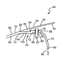
- FIG. 6 is detailed perspective view of a nose cone of FIG. 3 , constructed in accordance with the teachings of this disclosure
- FIG. 7 a detailed perspective view of a section of a fairing, constructed in accordance with the teachings of this disclosure.
- FIG. 8 is a flowchart illustrating the steps of the present disclosure.
- downstream and upstream are used with reference to the general direction of gas flow through the engine and the terms “axial”, “radial” and “circumferential”, and their derivatives, are generally used with respect to the longitudinal central axis of the engine.
- a gas turbine engine constructed in accordance with the present disclosure is generally referred to by reference numeral 10 .
- the gas turbine engine 10 includes a compressor 12 , a combustor 14 and a turbine 16 .
- the serial combination of the compressor 12 , the combustor 14 and the turbine 16 is commonly referred to as a core engine 18 .
- a core engine cowl 20 surrounds the core engine 18 .
- the engine 10 lies along a longitudinal central axis 22 .
- the pressurized air then enters the combustor 14 .
- the turbine 16 extracts energy from the hot combustion gases to drive the compressor 12 and a fan 26 , which includes airfoils 28 mounted onto a fan hub 29 .
- the airfoils 28 rotate so as to take in more ambient air. This process accelerates the ambient air 30 to provide the majority of the useful thrust produced by the engine 10 .
- the fan 26 has a much greater diameter than the core engine 18 . Because of this, the ambient air flow 30 through the fan 26 can be 5-10 times higher, or more, than the combustion air flow 32 through the core engine 18 .
- the ratio of flow through the fan 26 relative to flow through the core engine 18 is known as the bypass ratio.
- the fan 26 and core engine cowl 20 are surrounded by a fan cowl 34 forming part of a nacelle 36 .
- a fan duct 38 is functionally defined by the area between the core engine cowl 20 and the fan cowl 34 .
- the fan duct 38 is substantially annular in shape so that it can accommodate the air flow produced by the fan 26 . This air flow travels the length of the fan duct 38 and exits downstream at a fan nozzle 40 .
- a tail cone 42 may be provided at the core engine exhaust nozzle 44 to smooth the discharge of excess hot combustion gases that were not used by the turbine 16 to drive the compressor 12 and fan 26 .
- the core engine exhaust nozzle 44 is the annular area located between the tail cone 42 and a core engine case 46 , which surrounds the core engine 18 .
- the core engine case 46 is surrounded by the core engine cowl 20 .
- a nose cone 48 may be secured to the fan hub 29 to provide a smooth air flow 32 into the fan 26 .
- the nose cone 48 may include a spinner 50 , an aft support ring 52 and a fairing 54 .
- the spinner 50 may have a substantially conical shape with an axis aligned with the longitudinal central axis 22 . As such, the spinner 50 extends in a downstream axial direction from its apex 56 at an upstream end to a substantially circular base 58 at a downstream end.
- the spinner 50 includes a main portion 60 and a stepped portion 62 .
- the main portion 60 is disposed between the apex 56 and the stepped portion 62 .
- the stepped portion 62 is disposed between the main portion 60 and the base 58 .
- the stepped portion 62 extends in a substantially axially downstream direction and is approximately parallel to the longitudinal central axis 22 .
- the stepped portion 62 Moving axially towards the base 58 , the stepped portion 62 includes a receiving joint 64 and an interference fitting lip 66 .
- the interference fitting lip 66 is slightly offset radially away from the receiving joint 64 such that a first axial stop 68 forms on the outer surface 70 of the spinner 50 and a second axial stop 72 forms on the inner surface 74 of the spinner 50 .
- a plurality of first bolt holes 76 is disposed through the interference fitting lip 66 such that each of the plurality of first bolt holes 76 is equally spaced circumferentially from one another around the lip 66 .
- the aft support ring 52 may be substantially annular in shape.
- the aft support ring 52 may be formed such that an interference fitting flange 78 extends axially from a mounting portion 80 .
- the outer diameter 82 of the interference fitting flange 78 is slightly greater than the inner diameter (only the radius 84 is shown in FIG. 2 ) of the interference fitting lip 66 so that the interference fitting lip 66 is force-fitted over the interference fitting flange 78 creating a slight interference fit between the lip 66 and the flange 78 .
- the friction caused by the interference fit secures the lip 66 to the flange 78 and also maintains concentricity between the spinner 50 and the aft support ring 52 .
- the interference fit also transfers radial loads between the lip 66 and the flange 78 .
- the second axial stop 72 abuts the interference fitting flange 78 to control the axial depth of engagement of the aft support ring 52 into the spinner 50 , as well as to transfer axial loads from the spinner 50 to the aft support ring 52 .
- the interference fitting flange 78 may be scalloped at several locations to facilitate assembly by allowing for easier deformation of the outer diameter 82 of the flange 78 when force-fitting the interference lip 66 over the interference fitting flange 78 .
- a plurality of second bolt holes 86 is disposed through the interference fitting flange 78 so that each of the plurality of second bolt holes 86 is equally spaced circumferentially from one another around the flange 78 .
- Each of the plurality of second bolt holes 86 aligns with a corresponding first bolt hole 76 in the interference fitting lip 66 so that a radially extending bolt 87 may pass through the first and second bolt hole 76 , 82 further securing the interference fitting lip 66 to the interference fitting flange 78 .
- bolts are described to secure the lip 66 to the flange 78 other securing means may be used such as, but not limited to, rivets or bonding adhesives.
- the mounting portion 80 of the aft support ring 52 may include a plurality of tabs 88 .
- Each of the plurality of tabs 88 extends radially inwardly from the mounting portion 80 and is equally spaced circumferentially from one another around the mounting portion 80 .
- Each of the plurality of tabs 88 includes a third bolt hole 90 for receiving an axially extending bolt to secure the mounting portion 80 to the fan hub 29 .
- the third bolt holes 90 may be disposed directly on the mounting portion 80 without the tabs 88 .
- the fairing 54 is substantially frustoconical in shape with a smooth outer surface 92 and an inner surface 94 .
- the fairing 54 is formed with a circumferential heel 96 located at its upstream end 98 .
- the heel 96 protrudes from the inner surface 94 and includes a face 100 , which is directed radially inwardly.
- the face 100 corresponds with and is bonded to the receiving joint 64 such that the heel 96 abuts against the first axial stop 68 to control the position of the fairing 54 relative to the spinner 50 .
- the bonding may include, but is not limited to, adhesive, bolts and rivets.
- the outer surface 92 of the fairing 54 continues the smooth flow path surface of the main portion 60 of the spinner 50 and protects from fastener liberation into the flow path.
- a plurality of wedge-shaped supports 102 extends radially inwardly from the inner surface 94 of the fairing 54 .
- Each of the plurality of supports 102 is equally spaced circumferentially from one another and includes an edge 104 that abuts the outer surface 106 of the interference fitting lip 66 at a location that is between adjacent first bolt holes 76 .
- the spinner 50 and the fairing 54 may be manufactured from metallic or composite materials, which are light weight yet structurally robust to withstand impact from foreign objects, thermal and centrifugal expansion and engine rotation.
- FIG. 8 illustrates a flowchart 800 of a method of forming a nose cone for radial attachment to a gas turbine engine.
- Box 810 shows the step of forming a substantially conical spinner having an axially extending stepped portion with an inner diameter.
- Another step, shown in box 812 is to form an aft support ring having an outer diameter that is slightly greater than the inner diameter of the stepped portion.
- Box 814 shows the step of force-fitting the stepped portion over the aft support ring.
- Yet another step, as shown in box 816 is to secure the stepped portion to the aft support ring with a plurality of radially extending bolts.
- Box 818 illustrates the step of securing a fairing to the stepped portion.
- the present disclosure sets forth a nose cone with an aft support ring for radial attachment.
- the teachings of this disclosure can be employed to manufacture a nose cone with a less complex geometry than axial attached nose cones allowing for quicker production and assembly times.
- the nose cone provides an aerodynamic flow path that directs the inlet airflow smoothly through the fan.
Landscapes
- Engineering & Computer Science (AREA)
- Chemical & Material Sciences (AREA)
- Combustion & Propulsion (AREA)
- Mechanical Engineering (AREA)
- General Engineering & Computer Science (AREA)
- Aviation & Aerospace Engineering (AREA)
- Structures Of Non-Positive Displacement Pumps (AREA)
Abstract
Description
Claims (16)
Priority Applications (1)
| Application Number | Priority Date | Filing Date | Title |
|---|---|---|---|
| US15/026,692 US10208667B2 (en) | 2013-10-14 | 2014-05-23 | Nose cone with an aft support ring for radial attachment |
Applications Claiming Priority (3)
| Application Number | Priority Date | Filing Date | Title |
|---|---|---|---|
| US201361890637P | 2013-10-14 | 2013-10-14 | |
| US15/026,692 US10208667B2 (en) | 2013-10-14 | 2014-05-23 | Nose cone with an aft support ring for radial attachment |
| PCT/US2014/039311 WO2015057271A1 (en) | 2013-10-14 | 2014-05-23 | Nose cone with an aft support ring for radial attachment |
Publications (2)
| Publication Number | Publication Date |
|---|---|
| US20160237897A1 US20160237897A1 (en) | 2016-08-18 |
| US10208667B2 true US10208667B2 (en) | 2019-02-19 |
Family
ID=52828533
Family Applications (1)
| Application Number | Title | Priority Date | Filing Date |
|---|---|---|---|
| US15/026,692 Active 2035-05-01 US10208667B2 (en) | 2013-10-14 | 2014-05-23 | Nose cone with an aft support ring for radial attachment |
Country Status (3)
| Country | Link |
|---|---|
| US (1) | US10208667B2 (en) |
| EP (1) | EP3058198B1 (en) |
| WO (1) | WO2015057271A1 (en) |
Families Citing this family (2)
| Publication number | Priority date | Publication date | Assignee | Title |
|---|---|---|---|---|
| US9879698B2 (en) | 2015-10-26 | 2018-01-30 | Rolls-Royce North American Technologies Inc. | Nose cone and shaft balancing assembly |
| US11143103B2 (en) * | 2019-04-10 | 2021-10-12 | Rolls-Royce Corporation | Nose cone and fan assembly |
Citations (8)
| Publication number | Priority date | Publication date | Assignee | Title |
|---|---|---|---|---|
| US6447255B1 (en) * | 1998-12-29 | 2002-09-10 | Rolls-Royce Plc | Gas turbine nose cone assembly |
| JP2005105999A (en) | 2003-10-01 | 2005-04-21 | Ishikawajima Harima Heavy Ind Co Ltd | Gas turbine engine nose cone mounting structure |
| US20050231052A1 (en) | 2004-04-14 | 2005-10-20 | Pratt & Whitney Canada Corp. | Apparatus and method of balancing a shaft |
| DE102004018585A1 (en) | 2004-04-16 | 2005-12-01 | Rolls-Royce Deutschland Ltd & Co Kg | Gas turbine engine inlet cone, has upper surface whose structure varies in axial direction such that surface applies force on inflowing particles, relative to rotation axis, so that particles are conducted radially outwards along trajectory |
| DE102005013421A1 (en) | 2005-03-21 | 2006-09-28 | Rolls-Royce Deutschland Ltd & Co Kg | Intake cone for turbofan gas turbine engine, has attachment portion having axial contact surface abutted to one of guard rings as such that diagonal bolt hole can be bored into both guard ring and contact surface |
| US20090214354A1 (en) | 2008-02-26 | 2009-08-27 | Rolls-Royce Plc | Nose cone assembly |
| US20100215507A1 (en) | 2009-02-24 | 2010-08-26 | Rolls-Royce Plc | Mounting arrangement |
| EP2458146A1 (en) | 2010-11-30 | 2012-05-30 | Rolls-Royce plc | Nose cone assembly |
-
2014
- 2014-05-23 WO PCT/US2014/039311 patent/WO2015057271A1/en not_active Ceased
- 2014-05-23 EP EP14853438.1A patent/EP3058198B1/en active Active
- 2014-05-23 US US15/026,692 patent/US10208667B2/en active Active
Patent Citations (8)
| Publication number | Priority date | Publication date | Assignee | Title |
|---|---|---|---|---|
| US6447255B1 (en) * | 1998-12-29 | 2002-09-10 | Rolls-Royce Plc | Gas turbine nose cone assembly |
| JP2005105999A (en) | 2003-10-01 | 2005-04-21 | Ishikawajima Harima Heavy Ind Co Ltd | Gas turbine engine nose cone mounting structure |
| US20050231052A1 (en) | 2004-04-14 | 2005-10-20 | Pratt & Whitney Canada Corp. | Apparatus and method of balancing a shaft |
| DE102004018585A1 (en) | 2004-04-16 | 2005-12-01 | Rolls-Royce Deutschland Ltd & Co Kg | Gas turbine engine inlet cone, has upper surface whose structure varies in axial direction such that surface applies force on inflowing particles, relative to rotation axis, so that particles are conducted radially outwards along trajectory |
| DE102005013421A1 (en) | 2005-03-21 | 2006-09-28 | Rolls-Royce Deutschland Ltd & Co Kg | Intake cone for turbofan gas turbine engine, has attachment portion having axial contact surface abutted to one of guard rings as such that diagonal bolt hole can be bored into both guard ring and contact surface |
| US20090214354A1 (en) | 2008-02-26 | 2009-08-27 | Rolls-Royce Plc | Nose cone assembly |
| US20100215507A1 (en) | 2009-02-24 | 2010-08-26 | Rolls-Royce Plc | Mounting arrangement |
| EP2458146A1 (en) | 2010-11-30 | 2012-05-30 | Rolls-Royce plc | Nose cone assembly |
Non-Patent Citations (9)
| Title |
|---|
| DE102004018585 English Abstract. |
| DE102004018585 English Machine Translation. |
| DE102005013421 English Abstract. |
| DE102005013421 English Machine Translation. |
| English Abstract for JP2005105999A-Apr. 21, 2005; 2 pgs. |
| English Abstract for JP2005105999A—Apr. 21, 2005; 2 pgs. |
| European Search Report for Application No. EP 14 85 3438. |
| International Search Report for International Application No. PCT/US2014/039311; International Filing Date: May 23, 2014; dated Oct. 27, 2014; 5 pgs. |
| International Written Opinion for International Application No. PCT/US2014/039311; International Filing Date: May 23, 2014; dated Oct. 27, 2014; 6 pgs. |
Also Published As
| Publication number | Publication date |
|---|---|
| EP3058198A4 (en) | 2017-05-24 |
| US20160237897A1 (en) | 2016-08-18 |
| EP3058198A1 (en) | 2016-08-24 |
| EP3058198B1 (en) | 2019-04-03 |
| WO2015057271A1 (en) | 2015-04-23 |
Similar Documents
| Publication | Publication Date | Title |
|---|---|---|
| CA2833986C (en) | Low hub-to-tip ratio fan for a turbofan gas turbine engine | |
| US8240121B2 (en) | Retrofit dirt separator for gas turbine engine | |
| EP2805022B1 (en) | Gas turbine bypass vane system, gas turbine engine and method for manufacturing a bypass vane stage | |
| US9194330B2 (en) | Retrofitable auxiliary inlet scoop | |
| US8152461B2 (en) | Integrated inlet design | |
| US20130174562A1 (en) | Gas turbine engine, combustor and dome panel | |
| US9790860B2 (en) | Cooling passages for a mid-turbine frame | |
| US9920633B2 (en) | Compound fillet for a gas turbine airfoil | |
| US9863278B2 (en) | Air exhaust tube holder in a turbomachine | |
| US10168052B2 (en) | Combustor bulkhead heat shield | |
| US20190285276A1 (en) | Castellated combustor panels | |
| US20160186571A1 (en) | Mixing plenum for spoked rotors | |
| US8221073B2 (en) | Exhaust gas discharge system and plenum | |
| US10208667B2 (en) | Nose cone with an aft support ring for radial attachment | |
| US20120224960A1 (en) | Gas turbine engine case | |
| US20110286847A1 (en) | Gas turbine engine vanes | |
| US9670790B2 (en) | Turbine vane with mistake reduction feature | |
| US10774685B2 (en) | Gas turbine engine exhaust component | |
| US20150068214A1 (en) | Low thermal mass joint | |
| EP2910752B1 (en) | Fuel manifold fitting with integral support for a gas turbine engine and method of mounting a fuel supply manifold assembly | |
| US20160160668A1 (en) | Inner Diffuser Case Cone and Skirt | |
| US10343765B2 (en) | Toroidal spinner aft flange |
Legal Events
| Date | Code | Title | Description |
|---|---|---|---|
| AS | Assignment |
Owner name: UNITED TECHNOLOGIES CORPORATION, CONNECTICUT Free format text: ASSIGNMENT OF ASSIGNORS INTEREST;ASSIGNORS:KLING, COLIN J.;CLARKSON, STEVEN;REEL/FRAME:038171/0297 Effective date: 20131010 |
|
| STCF | Information on status: patent grant |
Free format text: PATENTED CASE |
|
| AS | Assignment |
Owner name: RAYTHEON TECHNOLOGIES CORPORATION, MASSACHUSETTS Free format text: CHANGE OF NAME;ASSIGNOR:UNITED TECHNOLOGIES CORPORATION;REEL/FRAME:054062/0001 Effective date: 20200403 |
|
| AS | Assignment |
Owner name: RAYTHEON TECHNOLOGIES CORPORATION, CONNECTICUT Free format text: CORRECTIVE ASSIGNMENT TO CORRECT THE AND REMOVE PATENT APPLICATION NUMBER 11886281 AND ADD PATENT APPLICATION NUMBER 14846874. TO CORRECT THE RECEIVING PARTY ADDRESS PREVIOUSLY RECORDED AT REEL: 054062 FRAME: 0001. ASSIGNOR(S) HEREBY CONFIRMS THE CHANGE OF ADDRESS;ASSIGNOR:UNITED TECHNOLOGIES CORPORATION;REEL/FRAME:055659/0001 Effective date: 20200403 |
|
| MAFP | Maintenance fee payment |
Free format text: PAYMENT OF MAINTENANCE FEE, 4TH YEAR, LARGE ENTITY (ORIGINAL EVENT CODE: M1551); ENTITY STATUS OF PATENT OWNER: LARGE ENTITY Year of fee payment: 4 |
|
| AS | Assignment |
Owner name: RTX CORPORATION, CONNECTICUT Free format text: CHANGE OF NAME;ASSIGNOR:RAYTHEON TECHNOLOGIES CORPORATION;REEL/FRAME:064714/0001 Effective date: 20230714 |